LIGHT PROJECTING METHOD AND DEVICE
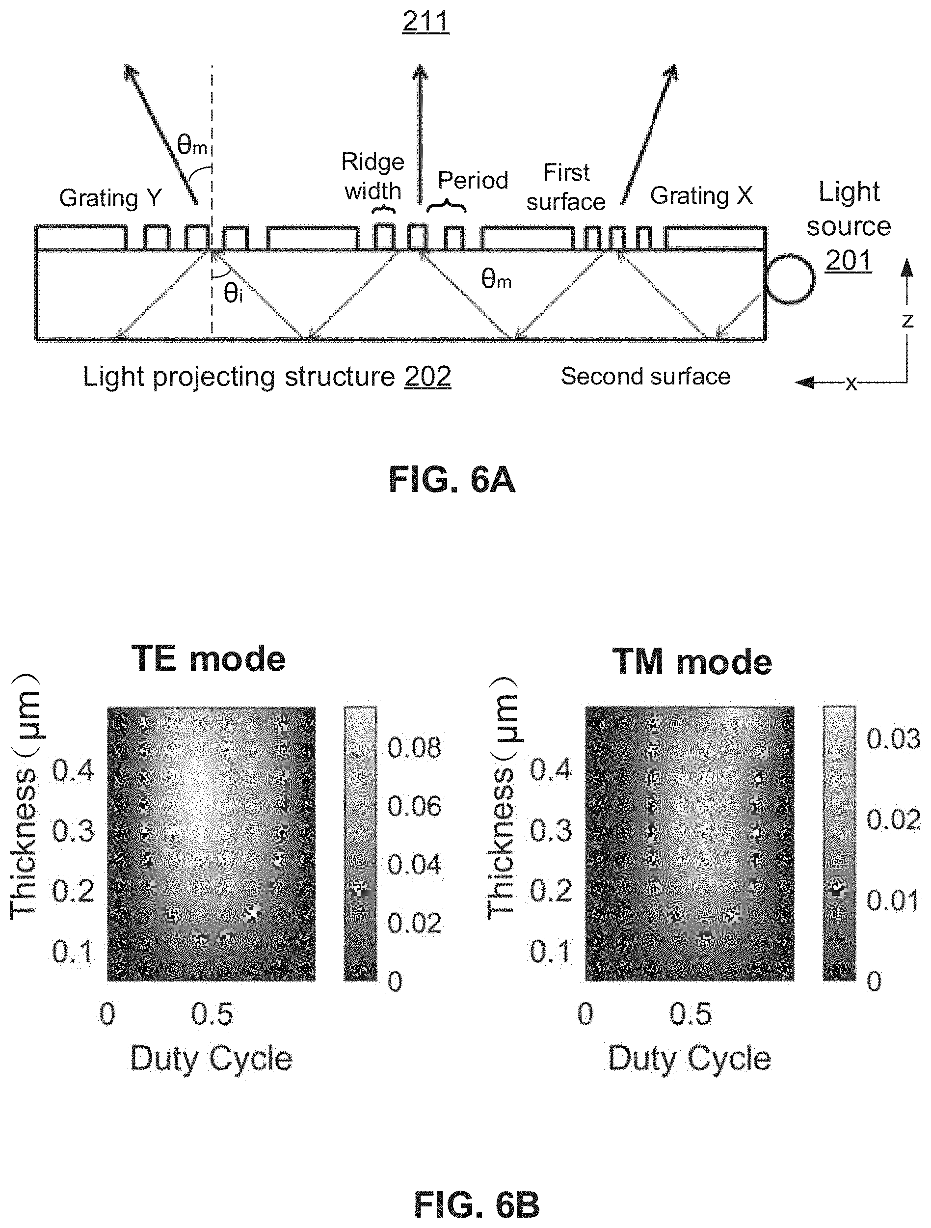
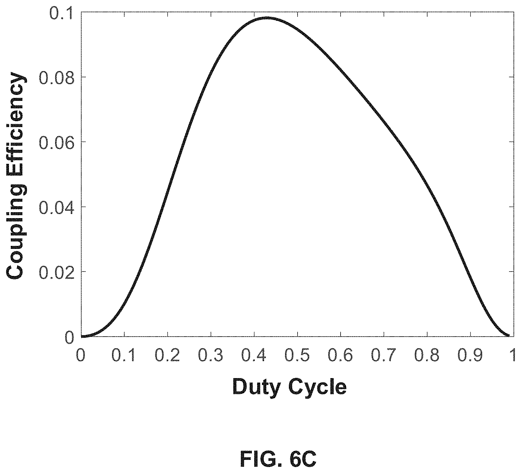
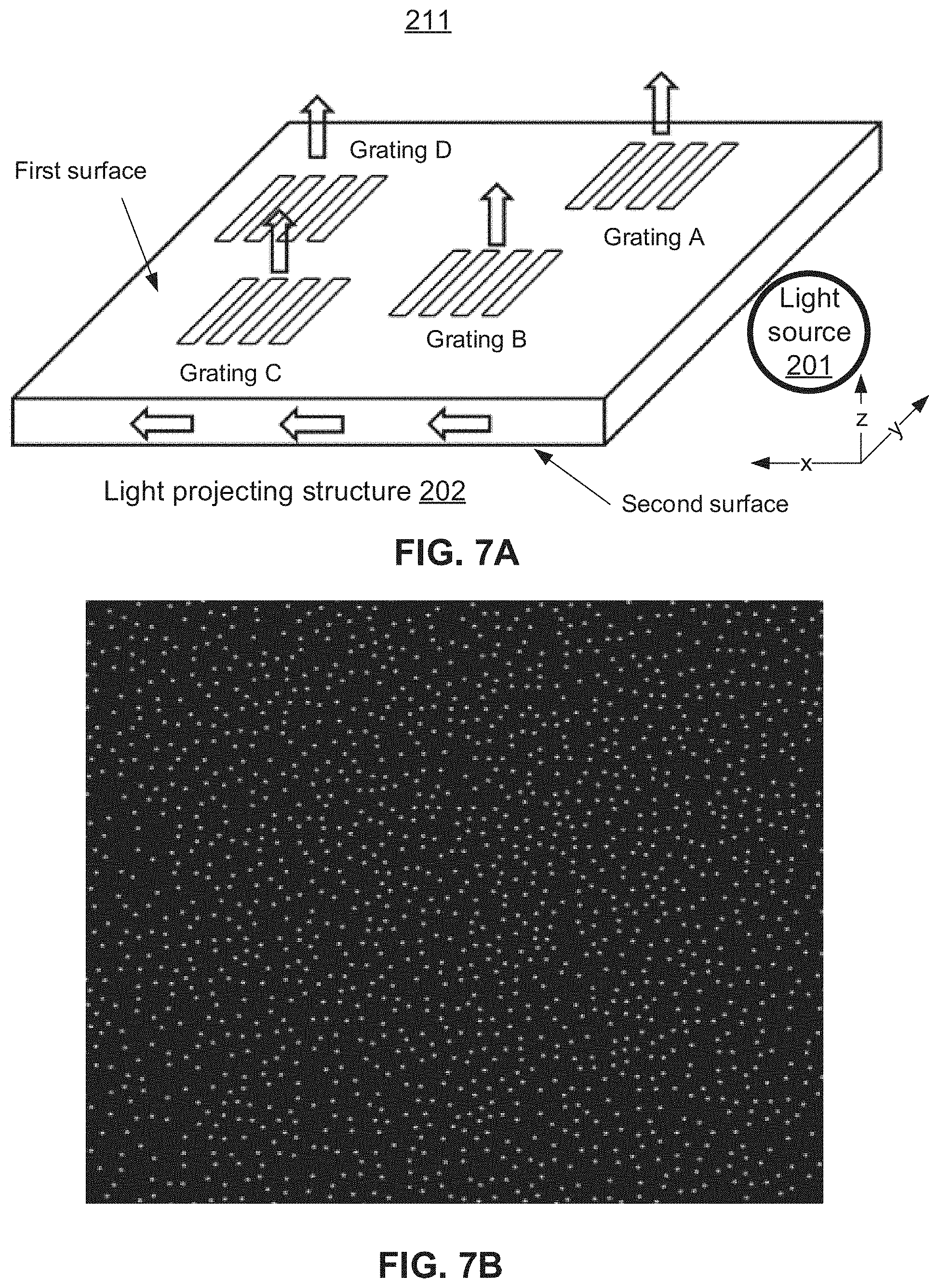
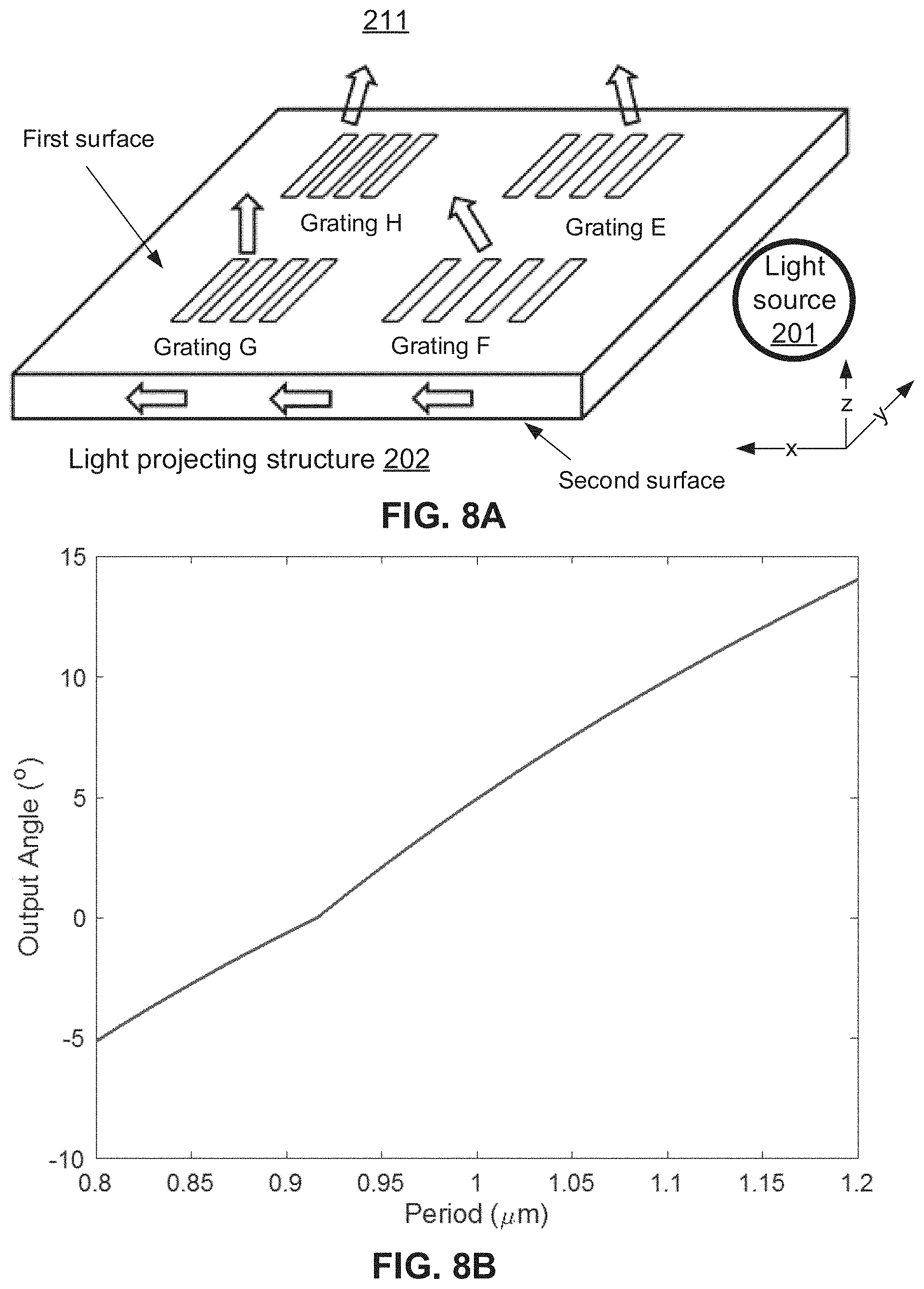
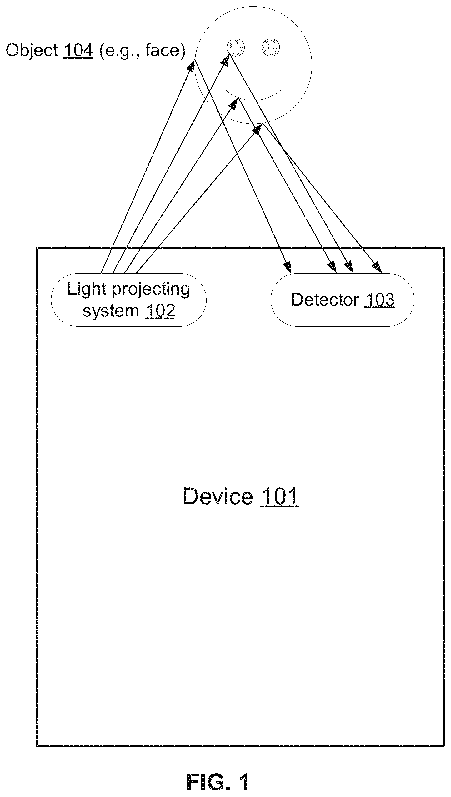
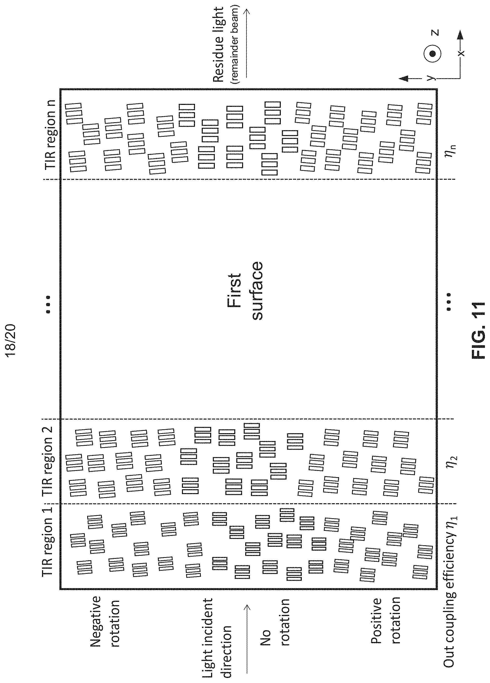
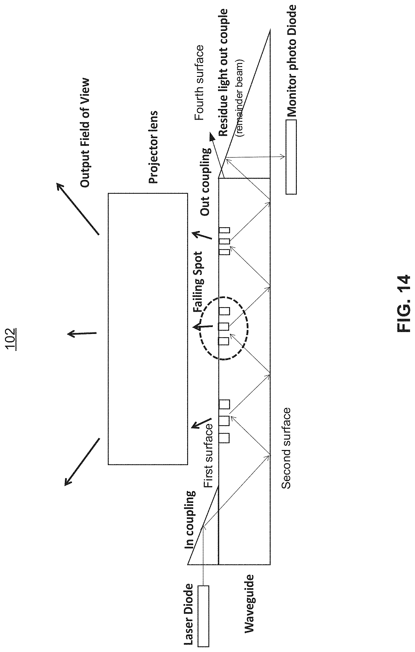
The present application is a continuation application of U.S. Non-provisional patent application Ser. No. 16/036,776, filed on Jul. 16, 2018 and entitled “LIGHT PROJECTING METHOD AND DEVICE”, which is incorporated herein by reference in its entirety. This disclosure relates to methods and devices for projecting light. Light projecting technologies are essential for enabling several important device functionalities. For example, structured light projecting is deployed in 3D camera modules of mobile phones for recognizing facial features. The projected light reflects off the facial features can be captured by a detector and analyzed by algorithms to “perceive” the topology of the face. Accordingly, authentication, emoji generation, image capture orientation, and other various functionalities can be designed based on inputs of the facial feature recognition. Current light projecting technologies are disadvantaged for high cost, large size, and low integration, which pose as bottlenecks for the development of device functionalities built upon the light projection. Therefore, improvements over the existing light projecting technologies are desirable for both the consumer market and the industry. Various embodiments of the present disclosure include light projecting structures (e.g., waveguides), devices, and systems. According to one aspect, a waveguide comprises a first surface, a second surface, a fourth surface, a light-absorbing material layer. The first surface comprises a first plurality of grating structures. The waveguide is configured to guide an in-coupled light beam to undergo total internal reflection between the first surface and the second surface. The first grating structures are configured to disrupt the total internal reflection to cause at least a portion of the in-coupled light beam to couple out of the waveguide and project from the first surface, the portion of the in-coupled light beam coupled out of the waveguide forming out-coupled light beams. A remainder of the in-coupled light beam undergoing the total internal reflection reaches the fourth surface after the out-coupling at each of the first grating structures. The light-absorbing material layer is parallel to the second surface and is separated by a gap from the second surface. The fourth surface may comprise another light-absorbing material layer for absorbing the remainder of the in-coupled light beam. In some embodiments, the out-coupled light beams converge from the first surface to form an upright cone of light and then diverge to form an inverted cone of light above the upright cone of light; and a cross-section of the upright or inverted cone parallel to the first surface comprises an array of dots corresponding to the out-coupled light beams In some embodiments, the out-coupled light beams diverge from the first surface to form an inverted cone of light, and a cross-section of the inverted cone parallel to the first surface comprises an array of dots corresponding to the out-coupled light beams. In some embodiments, the first surface is in an x-y plane, the in-coupled light beam propagates inside the waveguide substantially along the x-direction of the x-y plane, the out-coupled light beams propagate substantially along a z-direction normal to the x-y plane, and the first grating structures are distributed in the x-y plane with respect to corresponding (x, y) positions. The first grating structure is each associated with a grating depth, a duty cycle, a period, and an orientation in the x-y plane with respect to the z-direction. The first grating structures at different x-direction positions have at least one of different grating depths or different grating duty cycles. The first grating structures at different x-direction positions have different periods. The first grating structures at different y-direction positions have different orientations. In some embodiments, the waveguide is a planar waveguide, the first surface and the second surface are parallel to each other and are the largest surfaces of the planar waveguide, and the out-coupled light beams couple out of the waveguide from the first surface. In some embodiments, the waveguide is a planar waveguide, the first surface and the second surface are parallel to each other and are the largest surfaces of the planar waveguide, the first grating structures comprise volumetric gratings between the first surface and the second surface, and the out-coupled light beams couple out of the waveguide from the first surface. In some embodiments, the waveguide further comprises an elongated third surface opposite to the fourth surface. A light source couples light into the waveguide via the third surface to form the in-coupled light beam. The light from the light source is collimated into a line shape corresponding to the elongated third surface. In some embodiments, a prism is disposed on at least one of the first surface or the second surface, and a light source couples light into the waveguide via the prism to form the in-coupled light beam. In some embodiments, the waveguide further comprises a second plurality of grating structures on at least one of the first surface or the second surface. A light source couples light into the waveguide via the second plurality of grating structures to form the in-coupled light beam. In some embodiments, the light-absorbing material layer is a colored anodized aluminum layer. According to another aspect, a light projecting system comprises a waveguide comprising a first surface, a second surface, a fourth surface, and a light-absorbing material layer, the first surface comprising a first plurality of grating structures, and a light source coupling light into the waveguide to form an in-coupled light beam. The waveguide is configured to guide the in-coupled light beam to undergo total internal reflection between the first surface and the second surface. The first grating structures are configured to disrupt the total internal reflection to cause at least a portion of the in-coupled light beam to couple out of the waveguide and project from the first surface, the portion of the in-coupled light beam coupled out of the waveguide forming out-coupled light beams, the out-coupled light beams being configured to form an array of dots on a surface where the out-coupled light beams are projected on. A remainder of the in-coupled light beam undergoing the total internal reflection reaches the fourth surface after the out-coupling at each of the first grating structures. The fourth surface comprises the first light-absorbing material layer for absorbing the remainder of the in-coupled light beam. The light-absorbing material layer is parallel to the second surface and is separated by a gap from the second surface. In some embodiments, the light projecting system further comprises a detector configured to receive reflections of the out-coupled beams off multiple locations on a distant object to determine distances of the multiple locations relative to the light projecting system. According to another aspect, a waveguide comprises a first surface, a second surface, a fourth surface, and a light-absorbing material layer. The first surface comprises a first plurality of grating structures. The waveguide is configured to guide an in-coupled light beam to undergo total internal reflection between the first surface and the second surface. The first grating structures are configured to disrupt the total internal reflection to cause at least a portion of the in-coupled light beam to couple out of the waveguide and project from the first surface, the portion of the in-coupled light beam coupled out of the waveguide forming out-coupled light beams, the out-coupled light beams being configured to form an array of dots on a surface where the out-coupled light beams are projected on. These and other features of the systems, methods, and non-transitory computer readable media disclosed herein, as well as the methods of operation and functions of the related elements of structure and the combination of parts and economies of manufacture, will become more apparent upon consideration of the following description and the appended claims with reference to the accompanying drawings, all of which form a part of this specification, wherein like reference numerals designate corresponding parts in the various figures. It is to be expressly understood, however, that the drawings are for purposes of illustration and description only and are not intended as a definition of the limits of the invention. Certain features of various embodiments of the present technology are set forth with particularity in the appended claims. A better understanding of the features and advantages of the technology will be obtained by reference to the following detailed description that sets forth illustrative embodiments, in which the principles of the invention are utilized, and the accompanying drawings of which: Light projection is a key step for various applications such as 3D feature detection and 3D mapping. For example, depth camera modules used for industrial parts inspection and medical examination require determining depth information. Referring to Current light projection technologies for projecting the structured light beams employ a projection of a random dot array. The random dot array is achieved by randomly arranging a plurality of lasers, which inevitably drives up the cost and module size and increases integration difficulty. To at least mitigate the disadvantages of the current technologies, light projecting systems and methods are disclosed. In various embodiments, a light source may couple a light beam into a waveguide via a surface of the waveguide, which then projects multiple beams via gratings on another surface to form distributed output beams. The light source can be a single laser (e.g., an edge-emitting laser, a vertical-cavity surface-emitting laser (VCSEL)), a light-emitting diode, or the like, therefore obviating the need for multiple laser as required in existing technologies. The manufacturing cost can be further lowered, because the waveguide can be fabricated by standard lithography technologies. Moreover, the overall size of the light projecting system can be reduced due to the availability of integrating the waveguide on a substrate. Further, the disclosed waveguide is benefited from the absence of zeroth order diffraction interference, because zeroth order transmission is prohibited by the total internal reflection constraint. As understood by people of ordinary skill in the art, a waveguide is a structure that guides waves (e.g., electromagnetic waves (light) as in this disclosure) with minimal loss of energy by restricting expansion to one or more dimensions. To that end, in some embodiments, a light projecting system comprises a waveguide comprising a first surface and a second surface, the first surface comprising a first plurality of grating structures, a light source coupling light into the waveguide to form an in-coupled light beam, and a detector. The waveguide is configured to guide the in-coupled light beam to undergo total internal reflection between the first surface and the second surface. The grating structures (e.g., each of the first grating structures) are configured to disrupt the total internal reflection to cause at least a portion of the in-coupled light beam to couple out of the waveguide, the portion of the in-coupled light beam coupled out of the waveguide forming out-coupled light beams. The detector is configured to receive reflections of the out-coupled beams off multiple locations on a distant object to determine distances of the multiple locations relative to the light projecting system. Thus, the topology of the object's surface can be determined. A light projecting device comprising the light source and the light projecting structure (e.g., waveguide) is described in more details below with reference to As shown in In some embodiments, light beams emerging from the light projecting device 211 (out-coupled beams) may couple out from a surface of the light projecting device 211. Then, optionally, the light beams may pass through the projection lens structure 231 to be projected into the space. That is the projection lens structure 231 (e.g., one or more lenses) may be disposed above the waveguide (e.g., above a first surface of the waveguide described later). The projection lens structure 231 may be configured to receive the out-coupled beams and project the out-coupled beams into an environment containing the distant object. Alternatively, the light beams may be directly projected from the light projecting device 211 into the space. The projection lens structure 231 may comprise various lens or lens combinations (e.g., one to six pieces of separate lenses) for controlling directions of the projected beams. In some embodiments, the projection lens structure 231 may be configured to increase or decrease the field of view of the projected beam array. For example, the projection lens structure 231 may increase the field of view by diverging the projected beam array, or decrease the field of view by converging the projected beam array. In some embodiments, the projection lens structure 231 may be configured to collimate the each out-coupled beam. For example, per working distance requirement of different applications, the laser waist of the projected beam array as collimated by the projection lens structure 231 can vary from 10 mm to 1 meter. Thus, the projection lens structure 231 may collimate the output light to form clear image (e.g., a dot array) at a distance of interest (e.g., in the range of 10 cm to 10 m depending on the application). In some embodiments, the light source 201 emits light to optically couple into the light projecting structure 202 at an in-coupling (coupling light into the light projecting structure 202) area of one surface. The in-coupling setup can comprise end coupling, grating coupling, prism coupling, or the like. After entering the light projecting structure 202, the light undergoes total internal reflection within the light projecting structure 202 between a first surface and a second surface. The light projecting structure 202 may be made of a high refractive index material (e.g., plexiglass, quartz glass, single crystal silicon, fused silica, etc.). In one example, if quartz glass with a refractive index of 1.45 is used, the critical angle for total internal refraction is 44 degrees. Total internal reflection is sustained when the light traveling within the light projecting structure 202 strikes the first or second surface of the light projecting structure 202 at an angle larger than the critical angle with respect to the normal to the surface. The light travelling in the light projecting structure 202 may couple out of the light projecting structure 202 at various out-coupling areas (e.g., on the first surface). For example, the out-coupling areas may be areas having out-coupling structures (e.g., a transmissive grating, a reflective grating, a reflector, etc.). In some embodiments, the light projecting structure 202 comprises a first surface and a second surface. At least one of the first surface or the second surface comprises a first plurality of grating structures. In this disclosure, the grating structure may refer to a grating (e.g., optical grating), which is a regularly spaced collection of identical, parallel, and elongated elements. In this figure, for example, a profile of a ridge grating is shown, and each ridge grating may comprise identical, parallel, and elongated ridges (see Grating A in In some embodiments, as shown in In some embodiments, as shown in In some embodiments, as shown in In In In some embodiments, In some embodiments, the light projecting structure comprises a planar waveguide. The first surface and the second surface are parallel to each other and are the largest surfaces of the planar waveguide. The out-coupled light beams couple out of the light projecting structure from the first surface. The first surface or the second surface comprises the first plurality of grating structures. When the second surface comprises the first plurality of grating structures, the light projecting structure may further comprise a metal layer disposed on the second surface. Alternatively, the first grating structures comprise volumetric gratings between the first surface and the second surface. That is, the in-coupled light inside the light projecting structure 202 undergoes total internal reflection. While the rest continues total internal reflection, a portion of the light may break free of the total internal reflection when striking an out-coupling structure on the first surface, on the second surface, or inside the waveguide, and subsequently exit the waveguide from one of its surfaces (e.g., the first surface). Various out-coupling structures (transmissive grating, reflective grating, reflector, etc.) are described below. In In some embodiments, as shown in Similarly, In some embodiments, as shown in In some embodiments, as shown in In some embodiments, as shown in In some embodiments, as shown in Various configurations of the first grating structures may control the out-coupled light beams. As described below, the out-coupling efficiency may be determined by the grating depth (also referred to as “thickness”) and grating duty cycle ( In some embodiments, the gratings (first grating structures) disrupt the total internal reflection to cause the out-coupled light beams to project from the first surface, and the out-coupled light beams are configured to form an array of dots on a surface where the out-coupled light beams are projected on. For example, the out-coupled light beams may form an array of dots on a plane parallel to the first surface. In one example, the out-coupled light beams propagates normal to the first surface, and a cross-section of the out-coupled light beams parallel to the first surface comprises a random array of dots corresponding to the out-coupled light beams. In another example, the out-coupled light beams diverge from the first surface to form an inverted cone of light, and a cross-section of the inverted cone parallel to the first surface comprises a random array of dots corresponding to the out-coupled light beams ( In some embodiments, the direction of the out-coupled light beam may follow the following formula: where m is the diffraction order, λ is the wavelength, F is the period of the grating, n is the refractive index of the waveguide, θmis the angle of the out-coupling beam with respect to the normal of the first surface, and θiis the angle of the beam undergoing total internal reflection inside the waveguide with respect to the normal of the first surface. In some embodiments, the described out-coupling (light undergoing total internal reflection inside a waveguide couples out of the waveguide from areas having grating structures) occurs when the effective index of the +1 diffractive order (m=1) matches the effective index of the mode supported by the waveguide. Thus, to obtain out-coupling beams propagating parallel to the normal, and therefore (that is, θm=0), the grating period (labeled as “period” in the figure) can be obtained as: For example, when the waveguide is quartz glass (n=1.45), λ=940 nm, and θi=60°, Γ can be obtained to be 748 nm. Accordingly, the grating period can affect the angle of the out-coupling beam with respect to the normal. Substituting equation (2) into equation (1), it can be obtained that: Further, based on the condition for total internal reflection with a critical angle θc: It can be obtained that and therefore: To satisfy both (3) and (5) with m being an integer and |sin θm|≤1, m can only be 1. Therefore, the described out-coupling (light undergoing total internal reflection inside a waveguide coupling out of the waveguide from areas having the grating structures) may yield only the m=+1 order of out-coupled light, without interference of light of other transmissive diffraction orders. This is one of the advantages absent in existing light projecting technologies. In some embodiments, the grating has a geometry for a high coupling efficiency, that is, the percentage (portion) of the light undergoing total internal reflection that couples out of the waveguide at the grating. Thus, in this context, the coupling efficiency can be understood as an out-coupling efficiency. When the grating period is fixed, the coupling efficiency is determined by the grating depth and duty cycle (percentage of each period that the ridge structure occupies). Referring to the labels “ridge width” and “period” in In one example, extracting from the TE mode diagram in In some embodiments, as a portion of the light undergoing total internal reflection in the waveguide couples out of the waveguide at each grating, the power of the light remaining in the waveguide decreases after each out-coupling event. To ensure that out-coupled light beams in the dot array have about similar powers, the gratings can be designed such that the coupling efficiency increases as the distance of the grating from the light source 201 increases. For example, referring back to Thus, in some embodiments, each of the grating structures is associated with an out-coupling efficiency. The out-coupling efficiency increases monotonically along the x-direction. The out-coupling efficiency depends on a grating depth and a duty cycle of the grating structure. At least one of a grating depth or a duty cycle of the grating period varies in the x-direction to cause the out-coupling efficiency to increase monotonically along the x-direction. In one example, a grating depth of the grating structure increases monotonically in the x-direction, causing the out-coupling efficiency to increase monotonically along the x-direction. In another example, a duty cycle of the grating structure increases monotonically in the x-direction causing the out-coupling efficiency to increase monotonically along the x-direction. In another example, the x-y plane comprises a plurality of regions corresponding to various ranges of positions along the x-direction, the regions comprising a first region and a second region. The first region is the closest to an area of the in-coupled light beam coupling into the light projecting structure. The second region is the furthest from the area of the in-coupled light beam coupling into the light projecting structure. The grating structures in the same region have similar out-coupling efficiencies. The monotonic increase of the out-coupling efficiency along the x-direction causes a power of the out-coupled light beam from each of the grating structures in the first region to be similar to a power of the out-coupled light beam from each of the grating structures in the second region. As shown in In some embodiments, the gratings (e.g., grating A, grating B, grating C, grating D, etc.) may be fabricated at random locations on the first surface. The gratings may have the same grating period. From each grating, one out-coupling light beam couples out of the waveguide. Accordingly, when viewed from top, the out-coupling light beams may form a random dot array as shown in The light projecting device 211 may be similar in Thus, in some embodiments, the grating structures are each associated with a period, and the period varies for the grating structures along the x-direction. The variation of the period causes the out-coupled light beams to couple out of the waveguide at a range of angular deviations in the x-direction. In one example, the period monotonically varies along the x-direction. The monotonic variation of the period along the x-direction causes the out-coupled light beams to couple out of the light projecting structure at a range of angular deviations in the x-direction. In some embodiments, the in-coupled light travels from left to right inside the waveguide in the x-direction. The out-coupled light from grating M has a y-direction component of zero. That is, ignoring the x-direction component, the out-coupled light from gratin M propagates in the z-direction. The out-coupled light from grating N of a positive rotation angle has a negative y-direction component. That is, ignoring the x-direction component, the out-coupled light from gratin N propagates in the z-negative-y direction. The out-coupled light from grating K of a negative rotation angle has a positive y-direction component. That is, ignoring the x-direction component, the out-coupled light from gratin K propagates in the z-positive-y direction. Thus, considering the out-coupled beams from the gratings M, N, and, K, the out-coupled beams converge in the y-z plane. A plot of the out-coupled light beam angle (in the y-z plane with respect to the z-direction) against the grating rotation angle (with respect to the x-direction) is shown in Thus, in some embodiments, the grating structures are each associated with a degree of rotation with respect to the z-direction, and the degree of rotation varies for the grating structures along the y-direction. The variation of the degree of rotation causes the out-coupled light beams to couple out of the waveguide at a range of angular deviations in the y-direction. In one example, the degree of rotation varies monotonically clockwise or counter-clockwise. The monotonic variation of the degree of rotation causes the out-coupled light beams to propagate at various y-direction components. Each of In some embodiments, the waveguide further comprises an elongated third surface opposite to the fourth surface. The position of the third surface relative to the first and second surfaces are described above. A light source couples light into the waveguide via the third surface (in the “light incident direction” shown in In some embodiments, the divergence of the out-coupled beams may be controlled via the grating orientation and the grating period. For example, the divergence of the out-coupled beams in the y-direction may be controlled via the grating orientation, and the divergence of the out-coupled beams in the x-direction may be controlled via the grating period. In the y-direction of In some embodiments, In some embodiments, Referring to Referring to In some embodiments, the light power in the waveguide decreases along the propagation direction (x-direction in Referring to In some embodiments, the distribution of the grating locations on the first surface in Although the gratings in In some embodiments, the waveguide further comprises a reflective layer disposed on the second surface and covering the grating structures. The reflective layer may comprise one or more sub-layers of metal (e.g., alloy) and/or non-metal (e.g., dielectric). In one example, the reflective layer comprises at least one of the reflective layer comprises one or more sub-layers, each sub-layer comprising at least one of: aluminum, silver, gold, copper, titanium, chromium, nickel, germanium, indium, tin, platinum, palladium, zinc, aluminum oxide, silver oxide, gold oxide, copper oxide, titanium oxide, chromium oxide, nickel oxide, germanium oxide, indium oxide, tin oxide, platinum oxide, palladium oxide, zinc oxide, aluminum nitride, silver nitride, gold nitride, copper nitride, titanium nitride, chromium nitride, nickel nitride, germanium nitride, indium nitride, tin nitride, platinum nitride, palladium nitride, zinc nitride, aluminum fluoride, silver fluoride, gold fluoride, copper fluoride, titanium fluoride, chromium fluoride, nickel fluoride, germanium fluoride, indium fluoride, tin fluoride, platinum fluoride, palladium fluoride, or zinc fluoride. When the grating are fabricated on the second surface (as shown) or on the first surface, some amount of optical power may leak out of the waveguide (e.g., downward) due to symmetric first order diffraction. To minimize or suppress such leakage and maximize the coupling efficiency, a reflective layer (e.g., metal layer or a high reflection coating layer) may be deposited on the second surface. The metal can be aluminum, silver, gold, copper, or another high reflection metal. In some embodiments, light-absorbing material layers as shown can be used to minimize the background noise caused by leakage light from higher grating modes or by residue light from incomplete coupling. To minimize emitting the residue light from the waveguide, a light-absorbing material layer may be disposed on the sidewall of the waveguide directly (at the end of the light propagation in the waveguide). To reduce the leakage light from other grating modes, a light-absorbing material layer may be disposed with a gap from the second surface, to prevent from breaking the total internal reflection condition. The light-absorbing material layer can be a (colored) anodized aluminum layer, a rough surface, a black carbon paint layer, or another light-absorbing material layer. That is, the light projecting structure may further comprise a fourth surface, a first light-absorbing material layer, and a second light-absorbing material layer. A remainder of the in-coupled light beam undergoing the total internal reflection reaches the fourth surface after the out-coupling at each of the grating structures. The fourth surface comprises the light-absorbing material layer for absorbing the remainder of the in-coupled light beam. The second light-absorbing material layer is parallel to the second surface and is separated by a gap from the second surface. The second light-absorbing material layer may absorb light that leaks out of the waveguide from the second surface. The gap may prevent absorbing in-coupled light still travelling inside the waveguide. In some embodiments, as shown, a residue light out-coupling setup may be added to couple the residue light out of the waveguide (at the end of the light propagation in the waveguide), for example, via end coupling, grating coupling, or prism coupling described above. A detector such as a monitoring photo diode (e.g., silicon, germanium, or another diode) may be used to detect the out-coupled residue light. In one example, if any accident (e.g., chip cracking, water damage, vapor damage, laser dislocation, in-coupling prism dislocation, or another failure event) happens, the total internal reflection condition will be broken at the failing spot (an example of which is shown and labeled in the figure), which will result in change of the residue light. With a thresholding algorithm, the event of residue light changing can be timely detected by the monitoring photo diode, and the input laser can be shut off accordingly to ensure eye safety. If the input laser is not shut off, some of the laser beams may escape from the light projecting system with an uncontrolled power that may cause eye damage. The various features and processes described above may be used independently of one another, or may be combined in various ways. All possible combinations and sub-combinations are intended to fall within the scope of this disclosure. In addition, certain method or process blocks may be omitted in some implementations. The methods and processes described herein are also not limited to any particular sequence, and the blocks or states relating thereto can be performed in other sequences that are appropriate. For example, described blocks or states may be performed in an order other than that specifically disclosed, or multiple blocks or states may be combined in a single block or state. The exemplary blocks or states may be performed in serial, in parallel, or in some other manner. Blocks or states may be added to or removed from the disclosed exemplary embodiments. The exemplary systems and components described herein may be configured differently than described. For example, elements may be added to, removed from, or rearranged compared to the disclosed exemplary embodiments. Throughout this specification, plural instances may implement components, operations, or structures described as a single instance. Although individual operations of one or more methods are illustrated and described as separate operations, one or more of the individual operations may be performed concurrently, and nothing requires that the operations be performed in the order illustrated. Structures and functionality presented as separate components in exemplary configurations may be implemented as a combined structure or component. Similarly, structures and functionality presented as a single component may be implemented as separate components. These and other variations, modifications, additions, and improvements fall within the scope of the subject matter herein. Although an overview of the subject matter has been described with reference to specific exemplary embodiments, various modifications and changes may be made to these embodiments without departing from the broader scope of embodiments of the present disclosure. Such embodiments of the subject matter may be referred to herein, individually or collectively, by the term “invention” merely for convenience and without intending to voluntarily limit the scope of this application to any single disclosure or concept if more than one is, in fact, disclosed. The embodiments illustrated herein are described in sufficient detail to enable those skilled in the art to practice the teachings disclosed. Other embodiments may be used and derived therefrom, such that structural and logical substitutions and changes may be made without departing from the scope of this disclosure. The Detailed Description, therefore, is not to be taken in a limiting sense, and the scope of various embodiments is defined only by the appended claims, along with the full range of equivalents to which such claims are entitled. As used herein, the term “or” may be construed in either an inclusive or exclusive sense. Moreover, plural instances may be provided for resources, operations, or structures described herein as a single instance. Additionally, boundaries between various resources, operations, engines, and data stores are somewhat arbitrary, and particular operations are illustrated in a context of specific illustrative configurations. Other allocations of functionality are envisioned and may fall within a scope of various embodiments of the present disclosure. In general, structures and functionality presented as separate resources in the exemplary configurations may be implemented as a combined structure or resource. Similarly, structures and functionality presented as a single resource may be implemented as separate resources. These and other variations, modifications, additions, and improvements fall within a scope of embodiments of the present disclosure as represented by the appended claims. The specification and drawings are, accordingly, to be regarded in an illustrative rather than a restrictive sense. Conditional language, such as, among others, “can,” “could,” “might,” or “may,” unless specifically stated otherwise, or otherwise understood within the context as used, is generally intended to convey that certain embodiments include, while other embodiments do not include, certain features, elements and/or steps. Thus, such conditional language is not generally intended to imply that features, elements and/or steps are in any way required for one or more embodiments or that one or more embodiments necessarily include logic for deciding, with or without user input or prompting, whether these features, elements and/or steps are included or are to be performed in any particular embodiment. A waveguide comprises a first surface and a second surface. The first surface comprises a first plurality of grating structures. The waveguide is configured to guide an in-coupled light beam to undergo total internal reflection between the first surface and the second surface. The first grating structures are configured to disrupt the total internal reflection to cause at least a portion of the in-coupled light beam to couple out of the waveguide and project from the first surface, the portion of the in-coupled light beam coupled out of the waveguide forming out-coupled light beams, the out-coupled light beams being configured to form an array of dots on a surface where the out-coupled light beams are projected on. 1.-30. (canceled) 31. A waveguide, comprising: a first surface and a second surface, wherein:
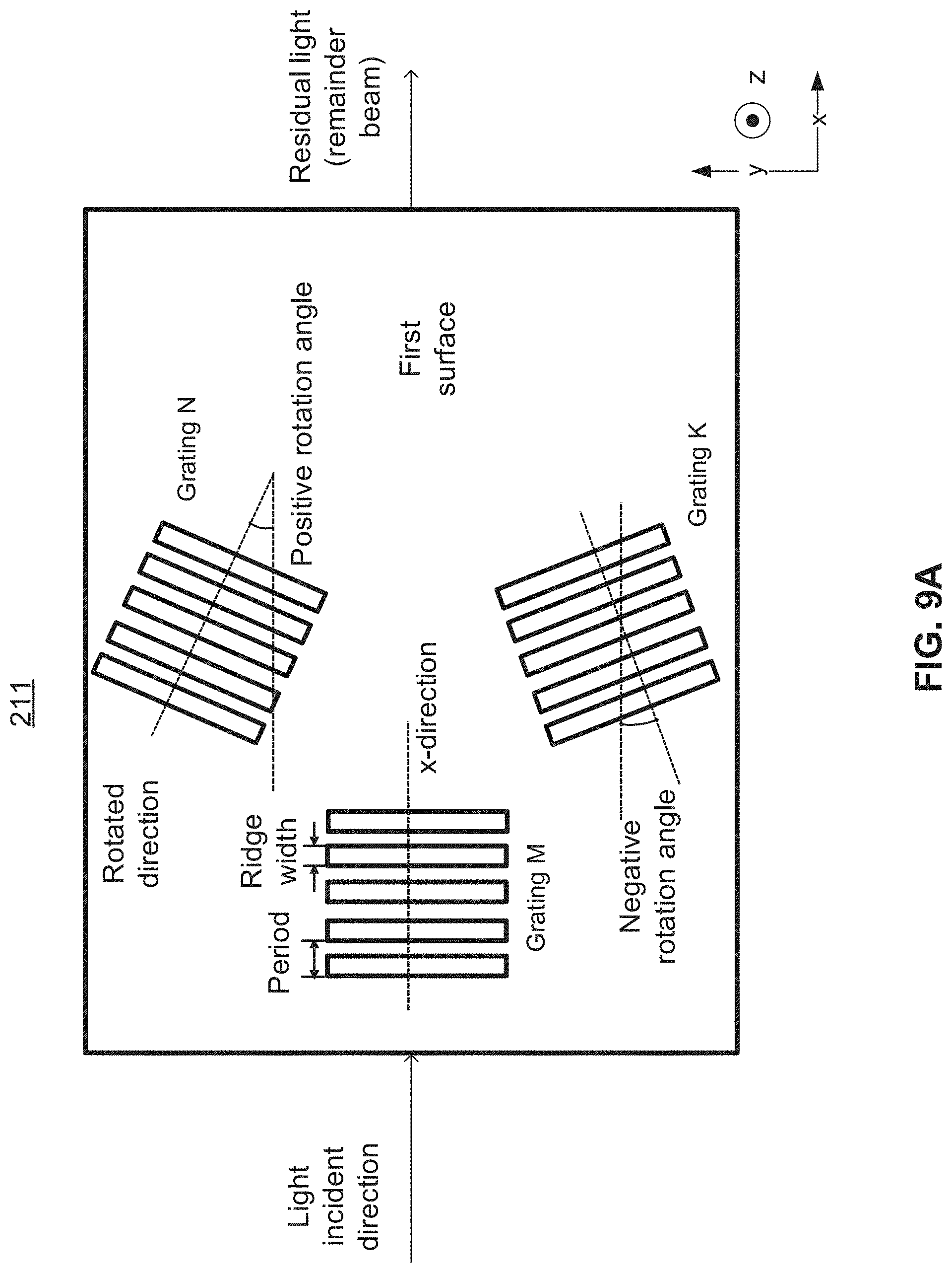
the first surface comprises a first plurality of grating structures; the waveguide is configured to guide an in-coupled light beam to undergo total internal reflection between the first surface and the second surface; the first plurality of grating structures are configured to disrupt the total internal reflection to cause at least a portion of the in-coupled light beam to couple out of the waveguide from the first surface, the portion of the in-coupled light beam coupled out of the waveguide forming out-coupled light beams; the first surface is in an x-y plane comprising an x-direction and a y-direction perpendicular to each other; the in-coupled light beam propagates inside the waveguide substantially along the x-direction of the x-y plane; the out-coupled light beams propagate substantially along a z-direction normal to the x-y plane; the first plurality of grating structures are each associated with a grating depth and a duty cycle in the x-y plane with respect to the z-direction; and the first plurality of grating structures at different x-direction positions have at least one of: different grating depths or different grating duty cycles. 32. The waveguide of the out-coupled light beams converge from the first surface to form an upright cone of light on top of the first plurality of grating structures. 33. The waveguide of the out-coupled light beams diverge from the first surface to form an inverted cone of light on top of the first plurality of grating structures. 34. The waveguide of the waveguide is a planar waveguide; the first surface and the second surface are parallel to each other and are the largest surfaces of the planar waveguide; and the out-coupled light beams couple out of the waveguide from the first surface. 35. The waveguide of the waveguide is a planar waveguide; the first surface and the second surface are parallel to each other and are the largest surfaces of the planar waveguide; the first plurality of grating structures comprise volumetric gratings between the first surface and the second surface; and the out-coupled light beams couple out of the waveguide from the first surface. 36. The waveguide of a light source couples light into the waveguide via the third surface to form the in-coupled light beam; and the light from the light source is collimated into a line shape corresponding to the elongated third surface. 37. The waveguide of a remainder of the in-coupled light beam undergoing the reflections reaches the fourth surface; and the fourth surface comprises a light-absorbing material layer for absorbing the remainder of the in-coupled light beam. 38. The waveguide of a light source couples light into the waveguide via the second plurality of grating structures to form the in-coupled light beam. 39. A waveguide, comprising: a first surface and a second surface, wherein:
the first surface comprises a first plurality of grating structures; the waveguide is configured to guide an in-coupled light beam to undergo total internal reflection between the first surface and the second surface; the first plurality of grating structures are configured to disrupt the total internal reflection to cause at least a portion of the in-coupled light beam to couple out of the waveguide from the first surface, the portion of the in-coupled light beam coupled out of the waveguide forming out-coupled light beams; the first surface is in an x-y plane comprising an x-direction and a y-direction perpendicular to each other; the in-coupled light beam propagates inside the waveguide substantially along the x-direction of the x-y plane; the out-coupled light beams propagate substantially along a z-direction normal to the x-y plane; the first plurality of grating structures are each associated with an orientation in the x-y plane with respect to the z-direction; and the first plurality of grating structures at different y-direction positions have different orientations. 40. The waveguide of the out-coupled light beams converge from the first surface to form an upright cone of light on top of the first plurality of grating structures. 41. The waveguide of the out-coupled light beams diverge from the first surface to form an inverted cone of light on top of the first plurality of grating structures. 42. The waveguide of the waveguide is a planar waveguide; the first surface and the second surface are parallel to each other and are the largest surfaces of the planar waveguide; and the out-coupled light beams couple out of the waveguide from the first surface. 43. The waveguide of the waveguide is a planar waveguide; the first surface and the second surface are parallel to each other and are the largest surfaces of the planar waveguide; the first plurality of grating structures comprise volumetric gratings between the first surface and the second surface; and the out-coupled light beams couple out of the waveguide from the first surface. 44. The waveguide of a light source couples light into the waveguide via the third surface to form the in-coupled light beam; and the light from the light source is collimated into a line shape corresponding to the elongated third surface. 45. The waveguide of a remainder of the in-coupled light beam undergoing the reflections reaches the fourth surface; and the fourth surface comprises a light-absorbing material layer for absorbing the remainder of the in-coupled light beam. 46. The waveguide of a light source couples light into the waveguide via the second plurality of grating structures to form the in-coupled light beam. 47. A light projecting system, comprising:
a waveguide comprising a first surface and a second surface, wherein the first surface comprises a first plurality of grating structures; and a light source coupling light into the waveguide to form an in-coupled light beam, wherein:
the waveguide is configured to guide the in-coupled light beam to undergo total internal reflection between the first surface and the second surface; the first plurality of grating structures are configured to disrupt the total internal reflection to cause at least a portion of the in-coupled light beam to couple out of the waveguide and project from the first surface, the portion of the in-coupled light beam coupled out of the waveguide forming out-coupled light beams; the first surface is in an x-y plane comprising an x-direction and a y-direction perpendicular to each other; the in-coupled light beam propagates inside the waveguide substantially along the x-direction of the x-y plane;
the out-coupled light beams propagate substantially along a z-direction normal to the x-y plane; the first plurality of grating structures are each associated with a grating depth and a duty cycle in the x-y plane with respect to the z-direction; and the first plurality of grating structures at different x-direction positions have at least one of: different grating depths or different grating duty cycles. 48. The light projecting system of the out-coupled light beams converge from the first surface to form an upright cone of light on top of the first plurality of grating structures. 49. A light projecting system, comprising:
a waveguide comprising a first surface and a second surface, wherein the first surface comprises a first plurality of grating structures; and a light source coupling light into the waveguide to form an in-coupled light beam, wherein:
the waveguide is configured to guide the in-coupled light beam to undergo total internal reflection between the first surface and the second surface; the first plurality of grating structures are configured to disrupt the total internal reflection to cause at least a portion of the in-coupled light beam to couple out of the waveguide and project from the first surface, the portion of the in-coupled light beam coupled out of the waveguide forming out-coupled light beams; the first surface is in an x-y plane comprising an x-direction and a y-direction perpendicular to each other; the in-coupled light beam propagates inside the waveguide substantially along the x-direction of the x-y plane; the out-coupled light beams propagate substantially along a z-direction normal to the x-y plane; the first plurality of grating structures are each associated with an orientation in the x-y plane with respect to the z-direction; and the first plurality of grating structures at different y-direction positions have different orientations. 50. The light projecting system of the out-coupled light beams converge from the first surface to form an upright cone of light on top of the first plurality of grating structures.CROSS REFERENCE TO RELATED APPLICATION
TECHNICAL FIELD
BACKGROUND
SUMMARY
BRIEF DESCRIPTION OF THE DRAWINGS
DETAILED DESCRIPTION
sin θm=(