LIQUID DELIVERY DEVICE AND FLUID CHROMATOGRAPH
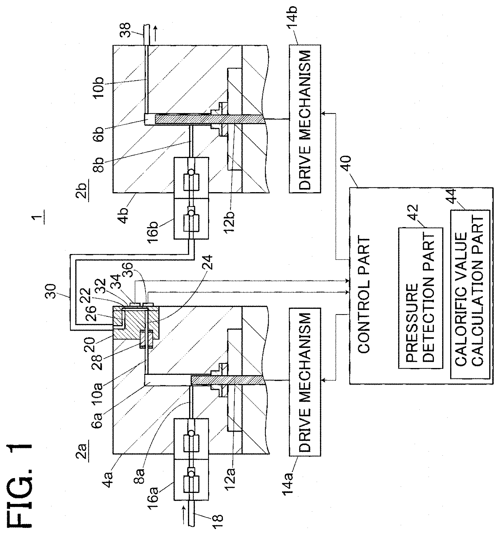
The present invention relates to a liquid delivery device used to deliver a mobile phase in an analyzer, such as a high performance liquid chromatograph (HPLC) or a supercritical fluid chromatograph (SFC), and a fluid chromatograph including the liquid delivery device. The liquid delivery device used in an HPLC system is required to have the ability to stably deliver a mobile phase at high pressure. For this reason, a liquid delivery device of a double plunger system in which two plunger pumps are connected in series or in parallel is generally used. For example, in the liquid delivery device in which two plunger pumps are connected in series, a primary side plunger pump on an upstream side and a secondary side plunger pump on a downstream side operate in a complementary manner. As a discharge stroke of the plunger pumps, there are a liquid delivery stroke by the primary side plunger pump and a liquid delivery stroke by the secondary side plunger pump. In the discharge stroke by the primary side plunger pump, the secondary side plunger pump performs suction operation while the primary side plunger pump discharges liquid, and part of the liquid discharged by the primary side plunger pump is sucked by the secondary side plunger pump. In the discharge stroke by the secondary side plunger pump, the secondary side plunger pump performs discharge operation, and, during the discharge operation, the primary side plunger pump performs suction operation. In the discharge stroke by the primary side plunger pump, a flow rate obtained by subtracting a suction flow rate of the secondary side plunger pump from a discharge flow rate of the primary side plunger pump is a liquid delivery flow rate of the liquid delivery device. In the discharge stroke by the secondary side plunger pump, the discharge flow rate of the secondary side plunger pump is a liquid delivery flow rate of the liquid delivery device. Such a liquid delivery device of a series double plunger system is provided with a valve for preventing backflow on each of an inlet side and an outlet side of the primary side plunger pump. When the primary side plunger pump performs the discharge operation, the valve on the inlet side closes, and the valve on the outlet side opens, and when the primary side plunger pump performs the suction operation, the valve on the inlet side opens and the valve on the outlet side closes. Since the suction operation of the primary side plunger pump is performed in a state where the valve on the outlet side is closed, pressure in a pump chamber of the primary side plunger pump after the suction operation of the primary side plunger pump is finished is in a state of being lower than system pressure (pressure in an analysis channel of an HPLC or an SFC). When, in this state, the pump that performs discharge operation is switched from the secondary side plunger pump to the primary side plunger pump, liquid is not discharged from the primary side plunger pump until pressure in a pump chamber of the primary side plunger pump increases to the same pressure as the system pressure. As a result, the liquid delivery flow rate is temporarily lowered and stability of the liquid delivery flow rate is lowered. Due to the above problem, during the discharge stroke by the secondary side plunger pump, the primary side plunger pump generally performs pre-compression operation to drive a plunger in a discharge direction so that pressure in a pump chamber can be increased to pressure close to the system pressure, in addition to the suction operation of liquid. The above similarly applies to a liquid delivery device of a parallel double plunger system in which two plunger pumps are connected in parallel, and while one plunger pump is performing discharge operation, the other plunger pump performs suction operation and pre-compression operation. When the pre-compression operation is performed, a mobile phase sucked into a pump chamber is compressed to generate heat, and a temperature of the mobile phase increases and the volume is expanded. After the above, in a process of flowing through a channel, the mobile phase discharged from the pump chamber is deprived of heat by a channel wall surface and the like to be cooled, and the volume shrinks. When such volumetric shrinkage occurs, an error occurs between an actual liquid delivery flow rate and an ideal value of a liquid delivery flow rate obtained by the product of a plunger cross-sectional area and a driving speed of the plunger, which causes lowering in liquid delivery accuracy and pulsation. As a solution to the above problems due to volumetric shrinkage of the mobile phase, a method of performing feedforward control for controlling a plunger speed based on prior knowledge of heat generation and cooling processes of the mobile phase, or a method of performing feedback control for controlling a plunger speed so that system pressure becomes equal to a target value have been proposed (see Patent Documents 1, 2 and 3). Patent Document 1: U.S. Pat. No. 8,535,016B2 Patent Document 2: U.S. Pat. No. 9,360,006B2 Patent Document 3: U.S. Pat. No. 8,297,936B2 Patent Document 4: US2010/299079A1 In a case where feedforward control is performed to control a plunger speed based on prior knowledge of heat generation and cooling processes of the mobile phase, reproducibility is required for the heat generation and cooling processes of the mobile phase. In particular, when the reproducibility of the cooling process of the mobile phase after being discharged from a pump chamber is low, volumetric shrinkage of the mobile phase after being discharged becomes unstable, which causes lowering in the liquid delivery accuracy. In view of the above, an object of the present invention is to improve the reproducibility of the cooling process of a fluid in a compressed state that is discharged from a plunger pump. A liquid delivery device according to the present invention includes one or more plunger pumps which comprises a pump head having a pump chamber provided in the inside, a plunger whose tip is slidably inserted into the pump chamber, and a drive mechanism that reciprocates the plunger in an axial direction thereof. At least one of the plunger pumps is a pressurizing pump that pressurizes a mobile phase including a compressible fluid sucked into the pump chamber and then discharges the mobile phase from the pump chamber. At least the pump head of the pressurizing pump includes a cooling part that is connected to an outlet channel from the pump chamber and causes the pump head to absorb heat of a mobile phase discharged from the pump chamber to cool the mobile phase. Here, the “pressurizing pump” in the present invention refers to a pump that pressurizes a mobile phase sucked into the pump chamber, that is, performs pre-compression operation, and then discharges the mobile phase in the pump chamber. In a liquid delivery device of a series double plunger system, the primary side plunger pump corresponds to the “pressurizing pump” in the present invention, and, in a liquid delivery device of a parallel type double plunger type, both the plunger pumps correspond to the “pressurizing pump” in the present invention. Patent Document 4 discloses that a heat exchange channel is provided in a pump head of a secondary side plunger pump of a liquid delivery device of a series type double plunger system, and a temperature of a mobile phase discharged from a primary side plunger pump (pressurizing pump) is made equal to that of a pump head of the secondary side plunger pump. In this disclosed technique, since the heat exchange channel is provided on the pump head of the secondary side plunger pump, a mobile phase that generates heat flows through a pipe (referred to as the primary side outlet pipe) that connects the pump head of the primary side plunger pump and the pump head of the secondary side plunger pump. However, since a temperature of the primary side outlet pipe periodically fluctuates due to the heat-generating mobile phase discharged from the primary side plunger pump, and the primary side outlet pipe has small heat capacity and is also exposed to outside air, the temperature of the primary side outlet pipe is unstable. In such a structure in which the mobile phase is cooled in a portion that is unstable in terms of temperature, the reproducibility of a cooling process of the mobile phase is not considered excellent. In contrast, in the liquid delivery device according to the present invention, a pump head of a pressurizing pump that performs pre-compression operation is provided with a cooling part that is connected to an outlet channel from a pump chamber and cools a mobile phase discharged from the pump chamber by causing the pump head to absorb heat of the mobile phase. Accordingly, a fluid discharged from the pump chamber is cooled to substantially the same temperature as the pump head of the pressurizing pump and then delivered to the outside of the pump head. As a result, the mobile phase cooled to substantially the same temperature as the pump head flows in an external pipe, such as a primary side outlet pipe connected to the pressurizing pump. In this manner, cooling of the mobile phase in a pipe that is unstable in terms of temperature is restricted, and the reproducibility of the cooling process of the mobile phase is improved. In a preferred embodiment, the cooling part is configured with a flat plate-shaped channel in which a ratio of an internal surface area to internal capacity is larger than that of the outlet channel. Further, the cooling part may be configured with a plurality of channels having a smaller cross-sectional area than the outlet channel, or a meandering channel having a smaller cross-sectional area than the outlet channel. In a further preferred embodiment, one wall surface of a channel forming the cooling part is configured to generate an elastic strain in accordance with pressure in the channel. The embodiment further includes a strain detection part that detects an amount of strain of the wall surface, and a pressure detection part that detects pressure in the cooling part based on an amount of strain of the wall surface detected by the strain detection part. In this manner, liquid delivery pressure of the pressurizing pump can be detected using the cooling part provided in the pressurizing pump. If the fluid delivery pressure of the pressurizing pump can be detected, the pre-compression operation of the pressurizing pump can be controlled with high accuracy based on the detected value. Further, a calorific value calculation part that calculates a calorific value of a mobile phase in the pump chamber based on a change amount of a pressure value detected by the pressure detection part may be further included. The calorific value of the mobile phase by the pre-compression operation can be calculated by the pressure detection part based on a pressure increase amount during the pre-compression operation of the pressurizing pump. The calorific value of the mobile phase can be calculated with a proportional coefficient between the pressure increase amount and the calorific value as βT/Cpρ, where a coefficient of thermal expansion of a fluid is β, a temperature is T, specific heat at constant pressure is Cp, and density is ρ. In a case where feedforward control of the pressurizing pump is performed based on the calorific value of the mobile phase, a discharge flow rate of the pressurizing pump can be controlled as described below according to the magnitude of the pressure increase amount during pre-compression operation of the pressurizing pump. When the pressure increase amount during the pre-compression operation of the pressurizing pump is large, it is predicted that the calorific value of the mobile phase is large and the volumetric shrinkage due to the cooling of the mobile phase is large. For this reason, a compensation flow rate for setting a flow rate actually delivered from the pressurizing pump to a predetermined delivery flow rate is set to be large, and the discharge operation of the pressurizing pump is controlled based on the compensated flow rate. In contrast, when the pressure increase amount during the pre-compression operation of the pressurizing pump is small, it is predicted that the calorific value of the mobile phase is small and the volumetric shrinkage due to the cooling of the mobile phase is small. For this reason, the compensation flow rate is set to be small, and the discharge operation of the pressurizing pump is controlled based on the compensation flow rate. Furthermore, when a pressure change per part time during the pre-compression operation is large, it is assumed that the compression of the mobile phase is more adiabatic and the heat generation of the mobile phase is large, so the compensation flow rate is made large. In contrast, when the pressure change per part time during the pre-compression operation is small, it is assumed that the compression of the mobile phase is more isothermal and the heat generation is small, so the compensation flow rate is made small. Further, a temperature detection part that detects the temperature of the cooling part may be further provided. If the temperature detection part for detecting the temperature of the cooling part is provided, it is possible to detect a temperature change of the mobile phase in the pump chamber of the pressurizing pump. In this case, a calorific value calculation part that calculates a calorific value of the mobile phase in the pump chamber based on a change amount of a temperature detected by the temperature detection part is preferably further included. If the calorific value of the mobile phase in the pump chamber of the pressurizing pump can be calculated, the feedforward control of the pressurizing pump described above can be performed. Specifically, when the temperature change amount of the mobile phase during the pre-compression operation of the pressurizing pump is large, it is predicted that the calorific value of the mobile phase is large and the volumetric shrinkage due to cooling of the mobile phase is large, so the compensation flow rate is made larger. In contrast, when the temperature change amount of the mobile phase during the pre-compression operation is small, it is predicted that the calorific value of the mobile phase is small and the volumetric shrinkage due to cooling of the mobile phase is small, so the compensation flow rate is reduced. Further, both the strain detection part and the temperature detection part described above may be provided. At this time, each detection part can be used to calculate the calorific value of the mobile phase as described above. Furthermore, the temperature detection part can also be used to correct the temperature characteristics of the strain detection part. In this manner, even in a case where the temperature of the strain detection part changes due to heat generation of the mobile phase, the output of the strain detection part can be corrected using the temperature detected by the temperature detection part, and an accurate pressure can be measured. In a case where the ambient temperature of the pressurizing pump fluctuates, the outlet pipe connected to the pump head of the pressurizing pump is easily affected, while the pump head has a larger heat capacity than the outlet pipe. For this reason, there is a temperature difference between the outlet pipe and the pump head. Then, the temperature of the mobile phase cooled to substantially the same temperature as the pump head in the cooling part provided in the pump head may change at the outlet pipe, which may impair the reproducibility of the cooling process of the mobile phase. In view of the above, an outlet pipe which is disposed outside the pump head of the pressurizing pump and communicates with the outlet channel of the pressurizing pump is preferably covered with a heat insulating member. Then, the temperature of the outlet pipe becomes stable, and a temperature difference does not easily occur between the pump head and the outlet pipe. In this manner, the reproducibility of the cooling process of the mobile phase can be improved. A fluid chromatograph at least includes an analysis channel, the above liquid delivery device that delivers a mobile phase in an analysis channel, a sample injection part that injects a sample into the analysis channel, a separation column that is provided downstream of the sample injection part on the analysis channel, and separates a sample injected into the analysis channel by the sample injection part into components, and a detector that is provided downstream of the separation column on the analysis channel and detects a sample component separated by the separation column. The “fluid chromatograph” means an analyzer, such as an HPLC or an SFC, that performs analysis while causing a fluid to flow as a mobile phase. In the liquid delivery device according to the present invention, a pump head of a pressurizing pump that performs pre-compression operation is provided with a cooling part that is connected to an outlet channel from a pump chamber and cools a mobile phase discharged from the pump chamber by causing the pump head to absorb heat of the mobile phase. Accordingly, a fluid discharged from the pump chamber is cooled to substantially the same temperature as the pump head of the pressurizing pump and then delivered to the outside of the pump head. As a result, the mobile phase cooled to substantially the same temperature as the pump head flows in an external pipe, such as a primary side outlet pipe connected to the pressurizing pump. In this manner, cooling of the mobile phase in a pipe that is unstable in terms of temperature is restricted, and the reproducibility of the cooling process of the mobile phase is improved. By improving the reproducibility of the cooling process of the mobile phase, the reproducibility of processes of expansion and shrinkage of the volume of the mobile phase is improved, and control of a liquid delivery flow rate in anticipation of expansion and shrinkage of the volume of the mobile phase is facilitated. The fluid chromatograph according to the present invention uses the above-described liquid delivery device as a liquid delivery device for delivering the mobile phase. Accordingly, liquid delivery with little influence from expansion and shrinkage of the volume of the mobile phase is performed, which improves the accuracy and reproducibility of analysis. Hereinafter, a liquid delivery device and a fluid chromatograph according to the present invention will be described with reference to the drawings. First, one embodiment of the liquid delivery device will be described with reference to A liquid delivery device 1 of this embodiment is a liquid delivery device in a series double plunger system in which a plunger pump 2 A tip of a plunger 12 The inlet channel 8 A cooling block 20 made from a heat conductive material, such as metal, is attached to the pump head 4 The inlet channel 8 Since the liquid delivery device 1 is a liquid delivery device of a series type, as shown in On the other hand, while the secondary side plunger pump 2 Here, according to heat transfer engineering, when a fluid flowing in a channel has a temperature difference with a channel wall surface (which is assumed to be isothermal) at an inlet of the channel, the temperature difference is known to be attenuated exponentially with respect to a channel length from the inlet. A characteristic length at which the temperature difference becomes 1/e=37% of the inlet depends on a flow rate, thermal diffusivity of the fluid, and the cross-sectional shape of the channel. The characteristic length required to cool the mobile phase that generates heat in the pump chamber 6 Since a diameter of a pump head of a typical plunger pump is 30 to 50 mm, in a case where an outlet channel is provided vertically from a pump chamber of the pump head, the length of the outlet channel is about 15 to 25 mm. This is similar to or shorter than the characteristic length calculated above and is not sufficient to cool the heated mobile phase. For this reason, in the prior art, the mobile phase in a state where heat generated at the time of the pre-compression operation remains is sucked into the pump chamber of the secondary side plunger pump through the primary side outlet pipe. This complicates and makes it difficult to understand the cooling process, and the effectiveness of the feedforward control of the primary side plunger pump taking into consideration thermal expansion and contraction of the mobile phase is impaired. Referring back to Note that the structure of the cooling part 22 is not limited to the example shown in The structure of the cooling part 22 shown in The mobile phase discharged from the pump chamber 6 In the embodiment of Returning to The control part 40 includes a pressure detection part 42 that is configured to obtain a pressure value in the cooling part 22 based on the signal value from the strain sensor 34, and a calorific value calculation part 44 configured to calculate a calorific value of the mobile phase in the pump chamber 6 A pressure value in the cooling part 22 obtained by a pressure detection part 42 is used for the pre-compression operation of the primary side plunger pump 2 Further, a temperature sensor 36 that detects a temperature of the cooling part 22 is attached to the cooling block 20, and an output signal of the temperature sensor 36 is also input to the control part 40. Note that although the temperature sensor 36 is not an essential constituent, a temperature of the mobile phase in the pump chamber 6 Further, both the strain sensor and the temperature sensor described above may be provided. At this time, each of the sensors can be used to calculate the calorific value of the mobile phase as described above. Furthermore, the temperature sensor can also be used to correct temperature characteristics of the strain sensor. In this manner, even in a case where the temperature of the strain sensor changes due to heat generation of the mobile phase, the output of the strain sensor can be corrected using the temperature detected by the temperature sensor, and an accurate pressure can be measured. The calorific value of the mobile phase in the pump chamber 6 Note that the liquid delivery device according to the present invention is not limited to one having the configuration of the embodiment described above. Hereinafter, another embodiment of the liquid delivery device will be described using A liquid delivery device 100 of the embodiment of The pump chamber 106 In this embodiment, a cooling block 120 is mounted on a tip of the pump head 104 The inlet channel 150 is a channel provided in an inlet block 148 provided on the cooling block 120 on the opposite side to the pump head 104 Note that, in this embodiment, the primary side outlet pipe 130 is covered with the heat insulating member 146. However, the heat insulating member 146 is not an essential component. In the liquid delivery device 100, the mobile phase flows through the cooling part 122 in either the suction operation or the discharge operation of the primary side plunger pump 102 The configuration of the secondary side plunger pump 102 Like the wall surface 32 of the cooling block 20 of the liquid delivery device 1 of A liquid delivery device 200 of the embodiment of Since both of the plunger pumps 202 In a pump head 204 The inlet channel 208 The outlet channel 210 As in the wall surface 32 of the cooling block 20 of the liquid delivery device 1 of The plunger pumps 202 As in the above-described embodiment, in the liquid delivery device 200 of a parallel type double plunger type, by providing the cooling parts 222 Note that, although not particularly shown in The liquid chromatograph of this embodiment includes an analysis channel 302, the above-described liquid delivery device 1, 100, or 200, a sample injection part 304, a separation column 306, a column oven 308, and a detector 310. The liquid delivery device 1, 100, or 200 is provided to deliver the mobile phase in the analysis channel 302. The sample injection part 304 is an autosampler that automatically injects a sample into the analysis channel 302. The separation column 306 is provided downstream of the sample injection part 304 on the analysis channel 302, and is for separating the sample injected by the sample injection part 304 into components. The separation column 306 is housed in the column oven 308 and has a temperature controlled at a set temperature. The detector 310 is provided downstream of the separation column 306 on the analysis channel 302 and is for detecting a sample component separated in the separation column 306. In the liquid chromatograph of this embodiment, the liquid delivery device 1, 100, or 200 is configured to deliver a single mobile phase to the sample injection part 304. As another embodiment, different mobile phases delivered by a plurality of liquid delivery devices may be mixed and delivered to the sample injection part 304. Such a configuration is generally known as a “high pressure gradient”. Further, as another different embodiment, a plurality of mobile phases may be mixed and supplied to the liquid delivery device 1, 100, or 200 via a mobile phase switching valve or a proportional valve, and delivered to the sample injection part 304. Such a configuration is generally known as a “low pressure gradient”. The liquid delivery device 1, 100, or 200 disclosed in the present invention can also be applied to liquid chromatographs of various channel configurations other than the embodiment shown in Note that, although 1, 100, 200: Liquid delivery device 2 4 6 8 108 10 12 14 16 18, 118, 218: Inlet piping 20, 120, 220 22, 122, 222 24, 124, 224 26, 126, 226 28: Joint 30, 130: Primary side outlet pipe 32, 132, 232 34, 134, 234 36: Temperature sensor 38, 138, 238: Outlet pipe 40: Control part 42: Pressure detection part 44: Calorific value calculation part 46: Heat insulation member 302: Analysis channel 304: Sample injection part 306: Separation column 308: Column oven 310: Detector A liquid delivery device includes a pump head having a pump chamber provided in the inside, a plunger whose tip is slidably inserted into the pump chamber, and at least one plunger pump having a drive mechanism that reciprocates the plunger in its axial direction. Then, at least one of the plunger pumps is a pressurizing pump that pressurizes a mobile phase including a compressible fluid sucked into the pump chamber and then discharges the mobile phase from the pump chamber, and at least the pump head of the pressurizing pump includes a cooling part that is connected to an outlet channel from the pump chamber, and allows the pump head to absorb heat of the mobile phase discharged from the pump chamber to cool the mobile phase. 1-10. (canceled) 11. A liquid delivery device comprising:
at least one or more plunger pumps, wherein the plunger pumps each include a pump head having a pump chamber provided in an inside, a plunger whose tip is slidably inserted into the pump chamber, and a drive mechanism that reciprocates the plunger in an axial direction thereof, at least one of the plunger pumps is a pressurizing pump that pressurizes a mobile phase including a compressible fluid sucked into the pump chamber and then discharges the mobile phase from the pump chamber, and
at least the pump head of the pressurizing pump includes a cooling part formed by channels connected with an outlet channel of the pump chamber, the cooling part, is configured to cause the pump head to absorb heat of a mobile phase that is discharged from the pump chamber and flows into the channels, and is provided to cool the mobile phase. 12. The liquid delivery device according to 13. The liquid delivery device according to 14. The liquid delivery device according to 15. The liquid delivery device according to wherein one wall surface of the channels forming the cooling part is configured to generate an elastic strain in accordance with pressure in the channel,
the liquid delivery device further comprising: a strain detection part that detects an amount of strain of the wall surface; and a pressure detection part that detects pressure in the cooling part based on an amount of strain of the wall surface detected by the strain detection part. 16. The liquid delivery device according to 17. The liquid delivery device according to 18. The liquid delivery device according to 19. The liquid delivery device according to 20. A fluid chromatograph at least comprising:
an analysis channel; a liquid delivery device that includes at least one or more plunger pumps, wherein the plunger pumps each include a pump head having a pump chamber provided in an inside, a plunger whose tip is slidably inserted into the pump chamber, and a drive mechanism that reciprocates the plunger in an axial direction thereof, at least one of the plunger pumps is a pressurizing pump that pressurizes a mobile phase including a compressible fluid sucked into the pump chamber and then discharges the mobile phase from the pump chamber, and at least the pump head of the pressurizing pump includes a cooling part formed by channels connected with an outlet channel of the pump chamber, the cooling part, is configured to cause the pump head to absorb heat of a mobile phase that is discharged from the pump chamber and flows into the channels, and is provided to cool the mobile phase; the liquid delivery device that delivers a mobile phase in an analysis channel; a sample injection part that injects a sample into the analysis channel; a separation column that is provided downstream of the sample injection part on the analysis channel, and separates a sample injected into the analysis channel by the sample injection part into components; and a detector that is provided downstream of the separation column on the analysis channel and detects the components separated by the separation columnTECHNICAL FIELD
BACKGROUND ART
PRIOR ART DOCUMENTS
Patent Documents
SUMMARY OF THE INVENTION
Problems to be Solved by the Invention
Solutions to the Problems
Effects of the Invention
BRIEF DESCRIPTION OF THE DRAWINGS
EMBODIMENTS OF THE INVENTION
DESCRIPTION OF REFERENCE SIGNS