METHOD AND SYSTEM FOR LOCATING MOBILE DEVICE RELATIVE TO VEHICLE
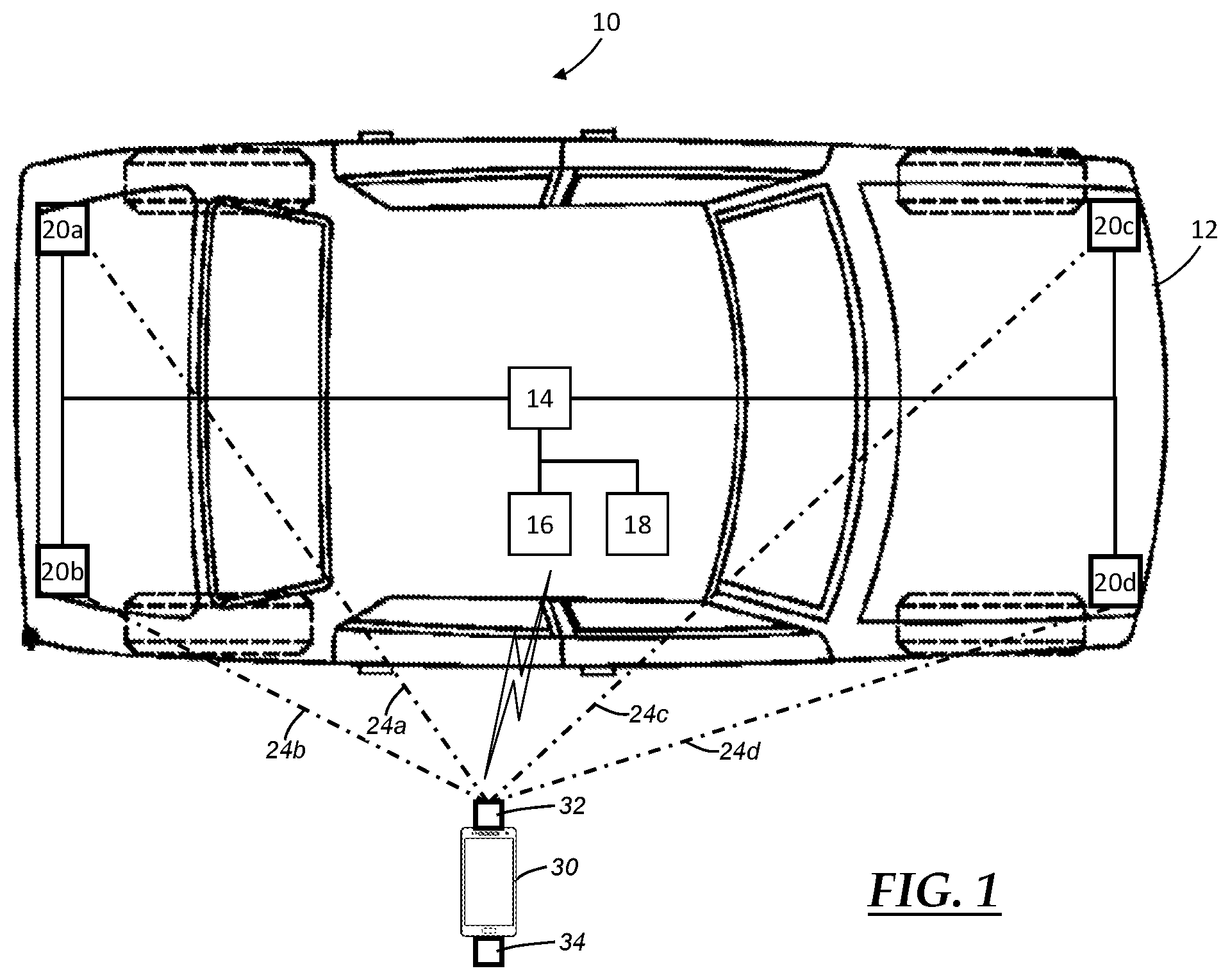
The present invention relates generally to locating a mobile device relative to a vehicle, such as when a user carrying the mobile device is approaching the vehicle in a parking lot or parking structure with a number of other vehicles. For many existing vehicles, a user can use a mobile device, such as a smartphone or key fob, to control certain vehicle functions. For instance, it is well known for a user to engage an app on a smartphone or a key fob to unlock a vehicle door or to remote start the vehicle. For some applications, such as those where the vehicle uses the direction of arrival (DOA) of the approaching user to activate some vehicle function, it may be necessary to determine the location of the mobile device relative to the vehicle. This is sometimes referred to as “localization.” To accurately determine the location of the approaching mobile device, low frequency waves can be used. However, low frequency waves are usually audible to humans and, therefore, disruptive. High frequency waves, on the other hand, are typically inaudible to humans, but can produce a certain amount of ambiguity in terms of the location of the mobile device, particularly if the speakers/microphones involved are not spaced close enough together. The method and system disclosed herein address these issues. According to one aspect, there is provided a method of locating a mobile device relative to a vehicle, the method comprising the steps: generating a modulated signal from a carrier wave and a baseband signal where the modulated signal is a mechanical wave, the carrier wave has an average carrier frequency and the baseband signal has an average baseband frequency that is less than the average carrier frequency; causing the modulated signal to be transmitted from one or more speakers located on the mobile device or the vehicle; causing the modulated signal transmitted from the speaker(s) to be received at one or more microphones located on the other of the mobile device or the vehicle over a plurality of localization paths; demodulating the modulated signal received at the microphone(s) for each of the plurality of localization paths to obtain a plurality of demodulated signals; and processing the plurality of demodulated signals to determine a location of the mobile device relative to the vehicle. According to another aspect, there is provided a vehicle-mobile device localization system, comprising: one or more mechanical wave input/output (I/O) devices installed on a vehicle; an electronic control unit (ECU) installed on the vehicle and communicatively coupled to the one or more mechanical wave I/O device(s), the ECU includes a processor and memory that stores computer instructions; wherein the computer instructions, when executed by the processor of the ECU in conjunction with computer instructions stored on a mobile device, cause the vehicle-mobile device localization system to either: transmit a modulated signal using the one or more mechanical wave I/O device(s) installed on the vehicle over a plurality of localization paths, where the transmitted modulated signal is generated from a carrier wave and a baseband signal and is a mechanical wave, the carrier wave has an average carrier frequency and the baseband signal has an average baseband frequency that is less than the average carrier frequency; or receive a modulated signal at the one or more mechanical wave I/O device(s) installed on the vehicle over a plurality of localization paths, where the received modulated signal was generated from a carrier wave and a baseband signal and is a mechanical wave, the carrier wave has an average carrier frequency and the baseband signal has an average baseband frequency that is less than the average carrier frequency, and wherein the vehicle-mobile device localization system demodulates the modulated signal for each of the plurality of localization path to obtain a plurality of demodulated signals, and then processes the plurality of demodulated signals to determine a location of a mobile device relative to the vehicle. One or more embodiments of the invention will hereinafter be described in conjunction with the appended drawings, wherein like designations denote like elements, and wherein: The system and method described herein provide for locating a mobile device relative to a vehicle using mechanical waves and modulation techniques. In one example, a high frequency carrier wave that is generally inaudible to humans is modulated with a low frequency baseband signal that provides for accurate localization in order to generate a modulated signal. The modulated signal is a mechanical or pressure wave, as opposed to an electromagnetic (EM) wave, that is produced or transmitted by one or more speaker(s) and is received by one or more microphone(s). By transmitting a modulated signal from a speaker on the mobile device to a number of microphones that are mounted on the vehicle and are specifically spaced apart, for example, the method and system are able to establish multiple localization paths that can then be used to determine the location of the mobile device, relative to the vehicle. The term “localization path,” as used herein, means the path travelled by a mechanical wave from a speaker to a microphone. In some embodiments, the speaker(s) are part of the mobile device while the microphone(s) are mounted on the vehicle, while in other embodiments, this is reversed so that the speaker(s) are mounted on the vehicle and the microphone(s) are part of the mobile device. In some embodiments, there is a single speaker and multiple microphones, whereas other embodiments have multiple speakers and a single microphone or even multiple speakers and multiple microphones. So long as multiple localization paths are established, the method and system can use any suitable combination of speaker(s) and microphone(s) to transmit, receive and process mechanical waves traveling along distinct localization paths in order to determine the relative location of the mobile device, with respect to the vehicle. Although the following description is provided in the context of an example where a single speaker is located on the mobile device and multiple microphones are located on the vehicle, it should be appreciated that the present application is not limited to such an example, as any of the aforementioned examples or other examples may be used instead. The audible frequency range for most humans extends between about 20 Hz and 19 kHz, although this can fluctuate based on factors such as the age of the person, etc. The present method and system use a high frequency carrier wave, such as one with a frequency that is equal to or greater than 15 kHz, so that the resulting modulated signal is generally inaudible or otherwise undetectable to most humans in the nearby vicinity. In order to achieve desirable localization accuracy, however, the microphones located on the vehicle must have a spacing that is less than one-half of the wavelength (½ λ) of the signals involved. By modulating the high frequency carrier wave with a low frequency baseband signal, for example one that has a frequency less than or equal to 500 Hz, the one-half wavelength spacing requirement becomes much easier to satisfy. To illustrate, assume that the speed of sound in air is typically about 340 m/s (these waves are mechanical waves). Since the wavelength of a high frequency carrier wave having a frequency of 19 kHz, for example, is about 0.018 m, the microphones on the vehicle would have to be spaced at a distance that is less than about 0.009 m (0.9 cm) apart in order to satisfy the one-half wavelength spacing requirement; such tight design constraints would be extremely difficult to economically achieve for most vehicle mounted microphones. Using the same assumptions, the wavelength of a low frequency baseband signal having a frequency of 500 Hz is about 0.68 m, which results in a much more manageable 0.34 m (34 cm) threshold to satisfy the one-half wavelength spacing requirement. In this manner, the present method and system combines the inaudible benefits of the high frequency carrier wave with the improved localization accuracy of the low frequency baseband signal to generate a modulated signal for determining the location of the mobile device relative to the vehicle. The vehicle-mobile device localization system 10, 10′ may utilize different combinations of devices, hardware, software, etc. on both a vehicle 12 and a mobile device 30 to carry out the method described herein. According to one example, system 10 includes an electronic control unit (ECU) 14, a wireless communications module (WCM) 16, a vehicle system module (VSM) 18, mechanical wave input/output (I/O) devices 20 ECU 14 may be coupled to and interact with any number of devices or components located throughout the vehicle, including the different mechanical wave I/O devices 20 The ECU 14 may include any suitable combination of hardware and/or software components, including a processor and memory. The processor can be any type of device capable of processing electronic instructions including microprocessors, microcontrollers, host processors, controllers, vehicle communication processors, General Processing Unit (GPU), accelerators, Field Programmable Gated Arrays (FPGA), and Application Specific Integrated Circuits (ASICs), to cite a few possibilities. It can be a dedicated processor used only for ECU 14 or can be shared with other vehicle systems, devices, components, etc. The processor can execute various types of electronic instructions, such as software and/or firmware programs stored in the memory of the ECU 14, which enable the ECU to carry out various functionality. The memory of the ECU 14 can be a non-transitory computer-readable medium; these include different types of random-access memory (RAM), including various types of dynamic RAM (DRAM) and static RAM (SRAM)), read-only memory (ROM), solid-state drives (SSDs) (including other solid-state storage such as solid state hybrid drives (SSHDs)), hard disk drives (HDDs), magnetic or optical disc drives, or other suitable computer medium that electronically stores information. In one example, the processor of the ECU 14 executes programs or processes data and the memory of the ECU stores programs or other data in order to help carry out or support at least a part of the present method. WCM 16 is a wireless communications module that enables the vehicle to communicate with a variety of other devices, including mobile device 30, and is coupled to ECM 14, VSM 18 and/or any number of other devices located in the vehicle. Unlike the mechanical wave I/O devices 20 Mechanical wave I/O devices 20 In the embodiment where one or more of the mechanical wave I/O devices 20 In the embodiment where one or more of the mechanical wave I/O devices 20 The collection of mechanical wave I/O devices 20 The mobile device 30 is an electronic device, such as a smart phone or a key fob, that includes a mechanical wave I/O device 32 and a wireless communication module 34. As already explained, the mechanical wave I/O device 32 can include a speaker, a microphone, or both, so long as at least two separate localization paths are established with the vehicle. For example, in the illustrated embodiments of An embodiment of the present method is illustrated in Beginning with step 210, the method receives an indication or otherwise detects some condition or event signaling it to begin transmitting a modulated signal (i.e., to start the method). In one example, step 210 detects that a user with a mobile device 30 is nearby, perhaps by determining that the vehicle 12 and the mobile device 30 have recently been wirelessly paired, such as via a SRWC protocol (e.g., Bluetooth™). In an example where the mobile device 30 is used as a key to access or control the vehicle 12, the WCM 34 can establish a SRWC connection with WCM 16 and can exchange authentication information therebetween (e.g., a virtual vehicle key). Once authenticated, the vehicle 12 can inform the mobile device 30 that it has been authenticated, which can act as the indication to start transmitting a modulated signal—in other words, as an indication that the vehicle-mobile device localization process can begin. It is possible for different indications, other than vehicle-mobile device pairing, to be used to initiate the vehicle-mobile device localization. The method 200 continues to steps 220 and 230. Steps 220 and 230 are described herein as being carried out simultaneously or nearly simultaneously. However, in other embodiments, these steps can be carried out serially, such as first carrying out step 220 and then step 230 or carrying out step 230 and then step 220. In step 220, carrier wave information is obtained and is designed so that the modulated signal is inaudible to most humans. In one embodiment, the carrier wave information includes a carrier wave frequency, a carrier wave amplitude, a carrier wave power and/or other parameters of the carrier wave to be used. When the frequency of the carrier wave, which is a mechanical or sound wave, is equal to or greater than approximately 19 kHz, the wave is generally inaudible to humans. And, in at least some embodiments, the average carrier frequency is at least thirty-eight times greater than the average baseband frequency. In one embodiment, the carrier wave information is stored in and obtained from memory located on the mobile device 30, but in other embodiments, the carrier wave information changes and is provided through the WCM 34 from the vehicle 12, a remote facility and/or some other source as part of an enhanced security feature, as described below. In step 230, baseband signal information is obtained and is designed so that the modulated signal will enable accurate localization. In one embodiment, the baseband signal information includes a baseband signal frequency, a baseband signal amplitude, a baseband signal, baseband modulation schemes, baseband center frequencies and/or other parameters of the baseband signal to be used. When the frequency of the baseband signal is less than or equal to 500 Hz (e.g., between 100 Hz and 500 Hz) and the corresponding half wavelength spacing requirement is satisfied, the method is usually able to accurately determine the location of the mobile device 30 relative to the vehicle 12. As explained below, the carrier wave and/or the baseband signal may have a single frequency (single tone) or multiple frequencies (e.g., multiple tone, narrowband, wideband, etc.). The phrases “average carrier frequency” and “average baseband frequency,” as used herein, respectively mean the average frequencies of the carrier wave and the baseband signal over the course of a particular signal transmission. Therefore, the condition that a baseband signal have an average baseband frequency that is less than an average carrier frequency means that, over the course of a particular signal transmission, the average frequency of the baseband signal must be less than the average frequency of the carrier wave. It is possible for the baseband signal to momentarily have a baseband frequency that is greater than a corresponding carrier frequency and still satisfy the previous condition, so long as the average frequency of the baseband signal is less than the average frequency of the carrier wave over the particular signal transmission. As with the carrier wave information, the baseband signal information may be stored locally in memory in the mobile device 30, it may be obtained wirelessly via WCM 34 from the vehicle 12, a remote facility and/or some other source. The baseband signal frequency may be selected based on the maximum I/O device distance. For example, the baseband signal frequency fBcan be selected to satisfy the following equations: where v is the speed of sound (or mechanical waves) in the atmosphere (or other medium), λBis the baseband signal length and dmaxis the maximum I/O device distance. As mentioned above, in one embodiment where a single speaker and a plurality of microphones are used, the distance dmaxcan be the maximum distance between any two of the microphones (e.g., microphones 20 The present method may utilize different modulation schemes when generating the modulated signal. For instance, it is possible for the carrier wave to be modulated with a baseband signal BShaving only a single baseband frequency (i.e., a single frequency or a single tone baseband signal). In other instances, such as when additional security measures are needed or when there is a significant amount of background noise, the carrier wave may be modulated with baseband signals having varying or changing baseband frequencies (i.e., multiple frequency or multiple tone baseband signal). In a modulation scheme using multiple frequency or tone baseband signals, the carrier wave is modulated with a rotating set of baseband signals that change according to a modulation scheme known to both the mobile device 30 and the vehicle 12. For example, the carrier wave can be modulated with a first baseband signal (e.g., a single tone baseband signal BS-single) for a period of time, then the carrier wave can be modulated with a second baseband signal (e.g., a narrow band baseband signal BS-narrow) for a period of time, and then the carrier wave can be modulated with a third baseband signal (e.g., a wide band baseband signal BS-wide) for a period of time, before cycling back to the first baseband signal and repeating the cycle. In such embodiments, a remote facility and/or some other source may provide both the mobile device 30 and the vehicle 12 with carrier wave information and/or baseband signal information ahead of time so that a mutually known and agreed upon modulation scheme can be established. For the single tone baseband signal BS-single, a single baseband frequency fBcan be included in the baseband signal information. For multi-tone baseband signals, such as the narrow band baseband signal BS-narrowand the wide band baseband signal BS-wide, parameters such as bandwidths, center frequencies, passwords, etc. may be included with the carrier wave and/or baseband signal information and can be sent to WCMs 16 and/or 34. After the carrier wave information (step 220) and the baseband signal information (step 230) are obtained, the method 200 continues to step 240. In step 240, a modulated signal is generated based on a baseband signal and a carrier wave. In one embodiment, the baseband signal is modulated over the carrier wave using amplitude modulation; however, in other embodiments, other types of modulation can be used instead. The carrier wave can be defined by the following carrier wave equation: where C(t) is the carrier wave equation, fcis the carrier frequency, and t is time. In at least some embodiments, the carrier frequency fcis specified by the carrier wave information as discussed above. In one embodiment, such as in the case where a single tone baseband signal is used, the following baseband equation can be used: where B(t) is the baseband signal equation, fBis the baseband (or modulation) frequency, and t is the time. Of course, other baseband equations can be used, such as when multi-tone (e.g., narrowband, wideband) baseband signals are used for modulation. In one embodiment, when multiple baseband signals (or signal types) are used, the baseband signals can be modulated over a common carrier wave and/or using a common carrier frequency. In continuing with the previous example of the carrier wave equation C(t) and the baseband equation B(t), a modulated signal equation that represents a modulated signal MSgenerated by applying the baseband signal (or wave equation) to the carrier wave can be obtained: where X(t) is the modulated signal equation, A is the amplitude of the carrier wave, and Mais amplitude of the baseband signal. The modulation parameters A and Macan be obtained during steps 220 and/or 230, for instance. Keeping with the example where a speaker 32 on the mobile device 30 is used to transmit a modulated signal to the vehicle 12, electrical signals in the form of output data that are representative of the desired modulated signal can be provided by the mobile device to the speaker for transmission. Although amplitude modulation using a single tone baseband signal is described above, various other modulation techniques using various different baseband signals can be used. For example, amplitude modulation using multiple frequency baseband signals, frequency modulation using a single frequency baseband signal, or frequency modulation using multiple frequency baseband signals could be used instead, to name just a few of the possibilities. In other embodiments, phase modulation or other modulation techniques can be used. The method then continues to step 250. In step 250, the modulated signal is transmitted through the surrounding atmosphere by one or more speakers. According to the previous example, output data in the form of electronic signals are sent to the speaker 32 of the mobile device 30 and then the speaker produces a mechanical or sound wave according to the modulation signal MS. The mechanical wave can be transmitted by the speaker 32 and received at the microphones 20 In embodiments that use multiple frequency baseband signals (e.g., the rotating example above), steps 230-250 can be carried out sequentially for each of the different baseband signals. For example, three sequentially generated modulated signals can be generated and transmitted, such as a first modulated signal based on a single tone baseband signal BS-single(referred to as a single tone modulated signal MS-single), a second modulated signal based on a narrowband baseband signal BS-narrow(referred to as a narrowband modulated signal MS-narrow), and a third modulated signal based on a wideband signal BS-wide(referred to as a wideband modulated signal MS-wide). In such a case, the multiple modulated signals can be transmitted by the speaker in a serial fashion. For example, first, the single tone modulated signal MS-singlecan be transmitted for 0.1 seconds, then the narrowband modulated signal MS-narrowcan be transmitted for 0.1 seconds, and then the wideband modulated signal MS-widecan be transmitted for 0.1 seconds. This process can then be repeated a certain number of times or until a feedback signal is received from the vehicle 12 (or other receiving device) (e.g., via WCM 16 and/or 34). With reference to In step 310, the modulated signal is received at a plurality of microphones. As discussed above, the modulated signal can be transmitted via mechanical waves from the speaker 32 of the mobile device 30. The modulated signal MSis then received at the microphones 20 In step 320, the received modulated signals are demodulated. For example, the four modulated signals MS,1to MS,4are each demodulated to obtain demodulated signals DS,1to DS,4. Various demodulation techniques can be used. The demodulated signals DS,1to DS,4represent the baseband signal BSas it is observed at each of the microphones 20 In step 330, which is optional, the demodulated signals can then be stored in memory. In one embodiment, the demodulated signals DS,1to DS,4are stored in the memory of the ECU 14. In other embodiments, another memory device of the vehicle 12 can be used. The method 300 may then continue to step 340. In step 340, the demodulated signals are processed to determine a location of the mobile device relative to the vehicle. In one embodiment, determining the location of the mobile device includes determining the direction of arrival (DOA) of the mobile device 30 (or speaker 32) relative to the vehicle 12 (or microphone array 22). Various processing techniques can be used to determine a DOA or other location characteristics pertaining to the signal. For example, the phase and/or amplitude of each of the demodulated signals is indicative of a length of that particular localization path (i.e., the phase of the signal when received at a microphone indicates the distance between the speaker and that particular microphone, within a one half wavelength; hence, the one half wavelength spacing requirements). By knowing the relative length of each of the localization paths, as well as the configuration of the mechanical wave I/O device array (i.e., the position of each of the microphones relative to one another), the location of the mobile device relative to the vehicle can be determined. In a particular embodiment, a MUSIC (Multiple Signal Classification) technique is applied to the demodulated signals DS,1to DS,4to help determine the DOA, as is understood by those skilled in the art. The method 300 then continues to step 350. In step 350, it is determined whether to accept the determination made in step 340. In one embodiment, the method may apply an acceptance threshold to the MUSIC score, although other acceptance or confirmation techniques may be used instead. When it is determined to accept the determination made in step 340, the method continues to step 360; otherwise, the method loops back to step 340. In the case that the results are not accepted, the location of the mobile device relative to the vehicle can be calculated using a next set of demodulated signals. In one embodiment, a next set of single tone demodulated signals DS,1-singleto DS,4-singlecan be used. As mentioned above, in other embodiments, numerous different baseband signals and/or modulation schemes can be used for modulation of the carrier wave, including single tone baseband signals, narrowband baseband signals, and wideband baseband signals. Step 340 can be carried out for the single tone demodulated signals DS,1-singleto DS,4-singleand, when it is determined in step 350 that the results are unacceptable, step 340 can be carried out again using the narrowband demodulated signals DS,1-narrowto DS,4-narrow. Then, in step 350, it can be determined whether the location determination results based on the narrowband demodulated signals DS,1-narrowto DS,4-narrowis acceptable and, if not, step 340 can be carried out using the wideband demodulated signals DS,1-wideto DS,4-wide. This process, which is optional, can be repeated until results are accepted. In step 360, a vehicle action or function is carried out. In one scenario where it is determined that the mobile device 30 (and hence the user) is approaching the vehicle 12 and is near a particular vehicle door, such as a right-rear passenger door, step 360 may unlock and/or open the right-rear passenger door. In another embodiment, the method may determine that the mobile device 30 (and hence the user) is near a trunk of the vehicle and, in response, step 360 may automatically unlock and/or open the trunk in an anticipatory fashion. For example, the ECU 14 can send commands or other electronic signals to VSM 18 instructing it to unlock and/or open one or more vehicle doors, trunks, etc. Such a feature can be particularly useful in a car sharing type of application where a user is looking for an unfamiliar vehicle in a parking lot or parking structure with a large number of other vehicles (possible of the same make and model), so that the method helps locate the user relative to the vehicle in question and takes some type of additional action to help identify the vehicle to the user. In another example, once the mobile device 30 (and hence the user) is located and deemed to be heading towards the vehicle or is rather close to the vehicle, the ECU 14 could send commands to a visual and/or audible device on the vehicle (e.g., lights, a horn, etc.) and instruct it to notify the user of their close proximity. In another embodiment, the ECU 14 can select a particular vehicle action to be carried out based on parameters, such as user proximity or location. Various other vehicle actions are possible as well, as the method is not limited to any particular one or ones. In other embodiments, the portion 200 of the method can be carried out by the vehicle 12 and the portion 300 of the method can be carried out by the mobile device 30. For example, the mechanical wave I/O devices 20 With reference to WCMs 26, 36 are short-range wireless communications (SRWC) devices that utilize electromagnetic signals, as opposed to mechanical or sound waves, to carry out various SRWC, such as those discussed above. The SRWC device 26 of the vehicle 12 is shown as being included in the ECU 14; however, the SRWC device 26 may be located as a part of a separate VSM in other embodiments. WCMs 28, 38 are long-range radio communication devices and, in at least some embodiments, include a cellular chipset (or other suitable circuitry) for carrying out cellular communications with the cellular carrier system 60. WCM 28, for example, may be a vehicle telematics unit. In one embodiment, the mobile device 30 can download and install computer instructions (or an application) that causes at least some of the method steps to be carried out. With reference to In step 410, authentication information and modulation information is transmitted from a remote facility to the vehicle. The authentication information can be a virtual vehicle key, user information, and/or other information that can be used to authenticate and/or authorize the vehicle user to access and/or control the vehicle 12. The modulation information can be carrier wave information and/or baseband signal information as discussed above (see steps 220 and 230 of the method 200 ( Steps 410 and 420 are described herein as being carried out at the same time. However, in other embodiments, these steps can be carried out serially, such as first carrying out step 410 and then 420 or carrying out step 420 and then step 410. In step 420, the authentication information and the modulation information is provided to the mobile device 30. In one embodiment, the authentication information and the modulation information is provided to the mobile device 30 via a connection with a remote server at the remote facility 50. For example, the authentication information and the modulation information is provided to the mobile device using the cellular carrier system 60. In another embodiment, the authentication information can be sent to the mobile device 30 from the remote facility 50 and, then, the vehicle 12 and the mobile device can establish a SRWC connection (step 430) when the mobile device 30 is authenticated by the vehicle 12 via the authentication information. Thereafter, using the secured SRWC connection, the modulation information can be communicated to the mobile device 30. The reverse is also true; the vehicle 12 can only receive the authentication while the mobile device 30 receives both the authentication information and the modulation information. Thereafter, the mobile device 30 can send the modulation information to the vehicle 12 via the secured SRWC connection. In step 430, the mobile device is authenticated by the vehicle. The authentication information can be used to authenticate the mobile device 30 for access to and/or control of the vehicle 12. In one embodiment, the vehicle 12 can detect the presence of the mobile device 30 using the SRWC device 26 and, then, the mobile device 30 and the vehicle 12 can establish a secure SRWC connection. After establishing the secure SRWC connection, the mobile device 30 can send at least part of the authentication information to the vehicle 12, which can then determine whether to authenticate the mobile device 30 and/or whether the mobile device 30 is authorized to access and/or control the vehicle. When it is determined that the mobile device is not authenticated by the vehicle (e.g., the mobile device 30 is not authentic, the mobile device 30 is not authorized), the method 400 ends. Otherwise, the method 400 continues to step 440. In step 440, a vehicle-mobile device localization process is carried out. In one embodiment, the methods 200 and/or 300 can be carried out by the vehicle-mobile device localization system 10. For example, in one embodiment, the mobile device 30 can transmit a modulated signal using one or more speakers 32 ( It is to be understood that the foregoing description is not a definition of the invention, but is a description of one or more preferred exemplary embodiments of the invention. The invention is not limited to the particular embodiment(s) disclosed herein, but rather is defined solely by the claims below. Furthermore, the statements contained in the foregoing description relate to particular embodiments and are not to be construed as limitations on the scope of the invention or on the definition of terms used in the claims, except where a term or phrase is expressly defined above. Various other embodiments and various changes and modifications to the disclosed embodiment(s) will become apparent to those skilled in the art. For example, the specific combination and order of steps is just one possibility, as the present method may include a combination of steps that has fewer, greater or different steps than that shown here. All such other embodiments, changes, and modifications are intended to come within the scope of the appended claims. As used in this specification and claims, the terms “for example,” “e.g.,” “for instance,” “such as,” and “like,” and the verbs “comprising,” “having,” “including,” and their other verb forms, when used in conjunction with a listing of one or more components or other items, are each to be construed as open-ended, meaning that that the listing is not to be considered as excluding other, additional components or items. Other terms are to be construed using their broadest reasonable meaning unless they are used in a context that requires a different interpretation. In addition, the term “and/or” is to be construed as an inclusive or. As an example, the phrase “A, B, and/or C” includes: “A”; “B”; “C”; “A and B”; “A and C”; “B and C”; and “A, B, and C.” A system and method for locating a mobile device relative to a vehicle using mechanical waves and modulation techniques. A high frequency carrier wave that is generally inaudible to humans is modulated with a low frequency baseband signal that provides for accurate localization in order to generate a modulated signal. The modulated signal is a mechanical or pressure wave, as opposed to an electromagnetic (EM) wave, that is transmitted by one or more speaker(s) and is received by one or more microphone(s). In one example, the modulated signal is transmitted from a speaker on the mobile device (e.g., a smart phone) to a number of microphones mounted on the vehicle at specific distances apart, so as to establish multiple localization paths whose differences in phase can be used to determine the location of the mobile device, relative to the vehicle. 1. A method of locating a mobile device relative to a vehicle, the method comprising the steps:
generating a modulated signal from a carrier wave and a baseband signal where the modulated signal is a mechanical wave, the carrier wave has an average carrier frequency and the baseband signal has an average baseband frequency that is less than the average carrier frequency; causing the modulated signal to be transmitted from one or more speakers located on the mobile device or the vehicle; causing the modulated signal transmitted from the speaker(s) to be received at one or more microphones located on the other of the mobile device or the vehicle over a plurality of localization paths; demodulating the modulated signal received at the microphone(s) for each of the plurality of localization paths to obtain a plurality of demodulated signals; and processing the plurality of demodulated signals to determine a location of the mobile device relative to the vehicle. 2. The method of 3. The method of 4. The method of 5. The method of 6. The method of 7. The method of 8. The method of 9. The method of 10. The method of 11. The method of 12. The method of 13. The method of 14. The method of 15. The method of 16. The method of 17. The method of 18. The method of 19. A vehicle-mobile device localization system, comprising:
one or more mechanical wave input/output (I/O) devices installed on a vehicle; an electronic control unit (ECU) installed on the vehicle and communicatively coupled to the one or more mechanical wave I/O device(s), the ECU includes a processor and memory that stores computer instructions; wherein the computer instructions, when executed by the processor of the ECU in conjunction with computer instructions stored on a mobile device, cause the vehicle-mobile device localization system to either:
transmit a modulated signal using the one or more mechanical wave I/O device(s) installed on the vehicle over a plurality of localization paths, where the transmitted modulated signal is generated from a carrier wave and a baseband signal and is a mechanical wave, the carrier wave has an average carrier frequency and the baseband signal has an average baseband frequency that is less than the average carrier frequency; or receive a modulated signal at the one or more mechanical wave I/O device(s) installed on the vehicle over a plurality of localization paths, where the received modulated signal was generated from a carrier wave and a baseband signal and is a mechanical wave, the carrier wave has an average carrier frequency and the baseband signal has an average baseband frequency that is less than the average carrier frequency, and wherein the vehicle-mobile device localization system demodulates the modulated signal for each of the plurality of localization path to obtain a plurality of demodulated signals, and then processes the plurality of demodulated signals to determine a location of a mobile device relative to the vehicle.TECHNICAL FIELD
BACKGROUND
SUMMARY
BRIEF DESCRIPTION OF THE DRAWINGS
DETAILED DESCRIPTION OF THE ILLUSTRATED EMBODIMENT(S)