Systems and Methods for Managing Hydrocarbon Emissions
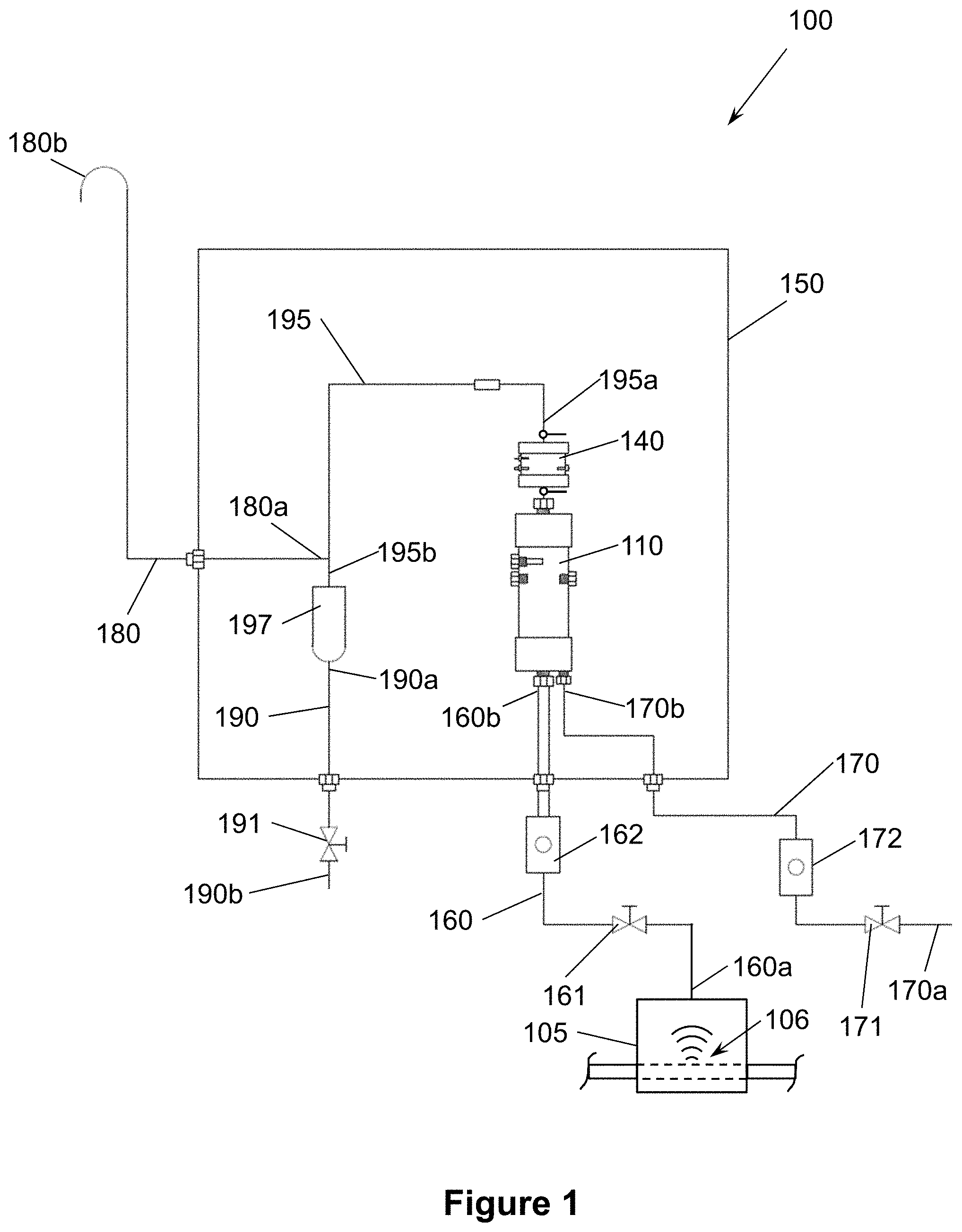
This application claims benefit of U.S. provisional patent application Ser. No. 62/825,497 filed Mar. 28, 2019, and entitled “Systems and Methods for Managing Hydrocarbon Emissions,” which is hereby incorporated herein by reference in its entirety for all purposes. Not applicable. This disclosure relates generally to systems and methods for reducing and/or preventing the release of hydrocarbon emissions such as methane into the atmosphere. More particularly, this disclosure relates to systems and methods for combusting hydrocarbon emissions to reduce and/or eliminate fugitive emissions. Hydrocarbon production systems (both actively producing and abandoned), hydrocarbon fluid analyzers, petrochemical plants, refineries, and other industrial activities may intermittently or continuously emit hydrocarbons to the surrounding environment, which may present environmental hazards. For example, wellheads and other equipment utilized for producing hydrocarbons from wells traversing subterranean earthen formations present a potential leak source of hydrocarbons in the upstream environment. In many jurisdictions, environmental regulations may limit and/or prevent the emission of hydrocarbons into the environment, even in relatively small trace quantities. For instance, some jurisdictions may require active monitoring of potential leak points to ensure that any hydrocarbons emitted to the surrounding environment are identified and mitigated. Embodiments of systems for reducing the release of hydrocarbons intermittently or continuously emitted from a hydrocarbon source into the atmosphere are disclosed herein. In one embodiment, the system comprises a hydrocarbon supply conduit having an inlet end configured to receive the emitted hydrocarbons from the hydrocarbon source and an outlet end. In addition, the system comprises an air supply conduit having an inlet end configured to be coupled to an air source and an outlet end. Further, the system comprises a combustion device coupled to the outlet end of the hydrocarbon supply conduit and the outlet end of the air supply conduit. The combustion device is configured to receive the hydrocarbons from the hydrocarbon supply conduit and the air from the air supply conduit. The combustion device is configured to ignite and combust the hydrocarbons. The system also comprises a catalytic converter spaced apart from the combustion device. Moreover, the system comprises a transfer conduit extending from an outlet of the combustion device to an inlet of a catalytic converter. The catalytic converter is configured to receive the combustion products and any un-combusted hydrocarbons from the transfer conduit. The catalytic converter includes a catalyst configured to oxidize the un-combusted hydrocarbons. Embodiments of system for reducing the release of hydrocarbons intermittently or continuously emitted from a hydrocarbon source into the atmosphere are disclosed herein. In one embodiment, the system comprises a hydrocarbon supply conduit having an inlet end configured to receive the emitted hydrocarbons from the hydrocarbon source and an outlet end. In addition, the system comprises a first flow meter and a first choke valve disposed along the hydrocarbon supply line, wherein the first flow meter is positioned between the first choke valve and the outlet end of the hydrocarbon supply conduit. Further, the system comprises an air supply conduit having an inlet end configured to be coupled to an air source and an outlet end. Still further, the system comprises a second flow meter and a second choke valve disposed along the air supply line. The second flow meter is positioned between the second choke valve and the outlet end of the air supply conduit. Moreover, the system comprises a combustion device coupled to the outlet end of the hydrocarbon supply conduit and the outlet end of the air supply conduit. The combustion device is configured to receive the hydrocarbons from the hydrocarbon supply conduit and the air from the air supply conduit. The combustion device is configured to ignite and combust the hydrocarbons. The system also comprises a catalytic converter coupled to the combustion device. The catalytic converter is configured to receive the combustion products and any un-combusted hydrocarbons from the combustion device. The catalytic converter includes a catalyst configured to oxidize the un-combusted hydrocarbons. The first flow meter is configured to measure a flow rate of the hydrocarbons in the hydrocarbon supply conduit and the second flow meter is configured to measure a flow rate of the air in the air supply conduit. The first choke valve is configured to be adjusted to control the flow rate of the hydrocarbons in the hydrocarbon supply conduit and the second choke valve is configured to be adjusted to control the flow rate of the air in the air supply conduit to achieve a pre-determined air-to-fuel ratio of the hydrocarbons and the air in the combustion device. Embodiments of methods for reducing the release of hydrocarbons intermittently or continuously emitted from a hydrocarbon source into the atmosphere are disclosed herein. In one embodiment, the method comprises (a) flowing the hydrocarbons to a combustion device. In addition, the method comprises (b) flowing air comprising oxygen to the combustion device. Further, the method comprises (c) substantially combusting the hydrocarbons and oxygen in the combustion device to produce combustion products, un-combusted hydrocarbons, and un-combusted oxygen. Still further, the method comprises (d) flowing the combustion products, the un-combusted hydrocarbons, and the un-combusted oxygen from the combustion device to a catalytic converter. The method also comprises (e) oxidizing the un-combusted hydrocarbons with the catalytic converter. Moreover, the method comprises (f) measuring the flow rate of hydrocarbons to the combustion device and measuring the flow rate of air to the combustion device during (a) and (b). The method also comprises (g) adjusting the flow rate of hydrocarbons to the combustion device or adjusting the flow rate of air to the combustion device during (f) to achieve a pre-determined air-to-fuel ratio. Embodiments described herein comprise a combination of features and characteristics intended to address various shortcomings associated with certain prior devices, systems, and methods. The foregoing has outlined rather broadly the features and technical characteristics of the disclosed embodiments in order that the detailed description that follows may be better understood. The various characteristics and features described above, as well as others, will be readily apparent to those skilled in the art upon reading the following detailed description, and by referring to the accompanying drawings. It should be appreciated that the conception and the specific embodiments disclosed may be readily utilized as a basis for modifying or designing other structures for carrying out the same purposes as the disclosed embodiments. It should also be realized that such equivalent constructions do not depart from the spirit and scope of the principles disclosed herein. For a detailed description of the disclosed embodiments, reference will now be made to the accompanying drawings in which: The following discussion is directed to various exemplary embodiments. However, one skilled in the art will understand that the examples disclosed herein have broad application, and that the discussion of any embodiment is meant only to be exemplary of that embodiment, and not intended to suggest that the scope of the disclosure, including the claims, is limited to that embodiment. Certain terms are used throughout the following description and claims to refer to particular features or components. As one skilled in the art will appreciate, different persons may refer to the same feature or component by different names. This document does not intend to distinguish between components or features that differ in name but not function. The drawing figures are not necessarily to scale. Certain features and components herein may be shown exaggerated in scale or in somewhat schematic form and some details of conventional elements may not be shown in interest of clarity and conciseness. Unless the context dictates the contrary, all ranges set forth herein should be interpreted as being inclusive of their endpoints, and open-ended ranges should be interpreted to include only commercially practical values. Similarly, all lists of values should be considered as inclusive of intermediate values unless the context indicates the contrary. In the following discussion and in the claims, the terms “including” and “comprising” are used in an open-ended fashion, and thus should be interpreted to mean “including, but not limited to . . . .” Also, the term “couple” or “couples” is intended to mean either an indirect or direct connection. Thus, if a first device couples to a second device, that connection may be through a direct engagement between the two devices, or through an indirect connection that is established via other devices, components, nodes, and connections. In addition, as used herein, the terms “axial” and “axially” generally mean along or parallel to a particular axis (e.g., central axis of a body or a port), while the terms “radial” and “radially” generally mean perpendicular to a particular axis. For instance, an axial distance refers to a distance measured along or parallel to the axis, and a radial distance means a distance measured perpendicular to the axis. Any reference to up or down in the description and the claims is made for purposes of clarity, with “up”, “upper”, “upwardly”, “uphole”, or “upstream” meaning toward the surface of the borehole and with “down”, “lower”, “downwardly”, “downhole”, or “downstream” meaning toward the terminal end of the borehole, regardless of the borehole orientation. As used herein, the terms “approximately,” “about,” “substantially,” and the like mean within 10% (i.e., plus or minus 10%) of the recited value. Thus, for example, a recited angle of “about 80 degrees” refers to an angle ranging from 72 degrees to 88 degrees. As previously described, a variety of industrial activities may produce intermittent or continuous hydrocarbon emissions that may require mitigation to reduce and/or eliminate the release of such hydrocarbon emissions to the atmosphere, and further, environmental regulations may limit and/or prevent the emission of hydrocarbons into the environment, even in trace quantities. For example, some environmental regulatory bodies such as the Environmental Protection Agency (EPA) require a vent control system when the release of fugitive hydrocarbon emissions is possible. In general, the purpose of the vent control system is to eliminate or significantly reduce the release of fugitive hydrocarbon emissions. While thermal oxidizers are available for vents that emit relatively large volumes of hydrocarbons (e.g., greater than 100 standard cubic feet per minute), vent control systems for relatively small volumes of hydrocarbons (e.g., less than 1.0 standard cubic foot per minute) are limited. For example, one conventional vent control system for eliminating undesirable hydrocarbon emissions employs a catalytic converter that is heated to a temperature sufficient to ignite and combust hydrocarbon emissions. However, such system is limited to relatively small quantities of intermittent fugitive emissions. For instance, one such conventional vent control system is limited to a maximum hydrocarbon flow rate of 1.0 liter per minute (˜0.035 standard cubic feet per minute) with a maximum BTU throughput of 750 BTU per hour. However, due to limited (if any) diagnostics to ensure the system is operating properly, a user may inadvertently exceed the maximum flow rate (1.0 liter per minute) and/or the BTU throughput (750 BTU per hour). Exceeding either of these operational parameters may result in damage to the system and/or the system not performing its intended purpose. Thus, although such conventional vent control systems can be used to combust fugitive hydrocarbon emissions, they are generally less suitable for dealing with continuous hydrocarbon emissions and/or larger quantities of hydrocarbon emissions due to limitations in volumetric and heat throughput. If additional capacity is desired, multiple systems may need to be installed, which potentially increases costs and the complexity of the infrastructure (e.g., plumbing) to route the emissions to multiple systems. In addition, due to limited (if any) diagnostics to monitor the performance of the catalyst in such conventional systems, the catalyst is often replaced on a periodic basis regardless of the actual remaining useful operating lifetime of the catalyst. To reduce the potential for undesirably releasing hydrocarbon emissions into the atmosphere, the catalyst may often be replaced at an overly frequent rate, which undesirably increases operating costs and the frequency at which the associated industrial activity that is producing the hydrocarbon emissions must be shut down to replace the catalyst. Accordingly, embodiments of hydrocarbon emission mitigation systems and methods described herein are designed and configured to accommodate relatively large throughputs of hydrocarbon emissions, and further, include “smart” features for monitoring catalyst performance and enhancing combustion of the hydrocarbon emissions. Referring now to In this embodiment, system 100 includes a hydrocarbon combustion device 110, a catalytic converter 140 coupled to the combustion device 110, an air supply conduit 170 coupled to combustion device 110, a hydrocarbon gas supply conduit 160 coupled to combustion device 110, a gas outlet conduit 180 coupled to catalytic converter 140, and a liquids outlet conduit 190 coupled to catalytic converter 140. Hydrocarbon gas supply conduit 160 supplies the intermittent and/or continuous stream of hydrocarbon emissions to combustion device 110, and air supply conduit 170 supplies pressurized air (including oxygen) to combustion device 110. As shown in As noted above, the inlet end 160 Air supply conduit 170 has a first or inlet end 170 As will be described in more detail below, choke valve 171 can be selectively adjusted to alter and control the volumetric flow rate of air through conduit 170 and into combustion device 110. Flow meter 172 is downstream of choke valve 171 and measures the volumetric flow rate of air through conduit 170 and into combustion device 110. In general, flow meter 171 can be any suitable flow meter known in the art for measuring the volumetric flow rate of air through a conduit or pipe, and choke valve 171 can be any suitable choke valve known in the art for controllably and selectively adjusting the volumetric flow rate of air through a conduit or pipe. Referring still to As will be described in more detail below, the hydrocarbons and oxygen in the air supplied to combustion device 110 are mixed and combusted within combustion device 110. The hydrocarbons, oxygen, and other components of air (e.g., nitrogen) that survive combustion within device 110 (e.g., in the case of incomplete combustion) and the combustion products (e.g., carbon dioxide and water vapor) flow from combustion device 110 to catalytic converter 140. The surviving hydrocarbons are oxidized in catalytic converter 140, and the remaining fluids (e.g., carbon dioxide, water, oxygen, and any other components of air) pass through and exit catalytic converter 140 into fluids outlet conduit 195. The fluids in outlet conduit 195 are divided into liquids and gases—the gases exit system 100 via gas outlet conduit 180 and the liquids exiting system 100 via liquids outlet conduit 190. It is to be understood that the air supplied to system 100 includes oxygen (about 21 vol %), nitrogen (about 78 vol %), and small amounts of a variety of other gases (e.g., argon, carbon dioxide, water vapor, etc.). The oxygen in the air combusts with the hydrocarbons in the combustion device 110, however, the remaining constituents (e.g., nitrogen, argon, carbon dioxide, water vapor, etc.) pass through combustion device 110 and catalytic converter 140 substantially unchanged. As will be described in more detail below, the combustion products produced in combustion device 110 include carbon dioxide and water vapor. Those combustion products generally mix with the remaining constituents of the air and pass through catalytic converter 140 along with any un-combusted hydrocarbons and un-combusted oxygen (if any). For purposes of clarity and further explanation, the constituents of air other than oxygen will generally be disregarded with the understanding they flow along with the combustion products through catalytic converter 140 and the other components of system 100 downstream of catalytic converter 140. As shown in Referring now to Housing 111 includes a gas inlet port 114 in end 111 Referring still to Housing 111 also includes an ignitor port 128 for each ignitor 123, a sensor port 129 Referring still to Housing 141 includes an inlet port 144 in end 141 Referring still to Housing 141 also includes a heater port 148 for each heater 153 and a sensor port 149 for temperature sensor 154. In this embodiment, ports 148, 149 extend radially through outer wall 142 with sensor port 149 being axially positioned between heater ports 148 and end 141 Referring still to Referring again to Liquid trap 197 receives and captures liquid condensate in outlet conduit 195. In particular, outlet conduit 195 includes a vertical section extending upward from outlet end 195 Gas outlet conduit 180 receives gases flowing through outlet conduit 195 and vents the gases to the atmosphere. In particular, gas outlet conduit 180 has an inlet end 180 Referring now to Beginning in block 201, method 200 includes capturing the intermittently and/or continuously emitted hydrocarbons 106 from source 105. Next, in block 202, the captured hydrocarbon emissions and oxygen are directed and flowed to a system 100. In particular, the captured hydrocarbons emissions are directed into and flow through conduit 160 and diffuser 121 into combustion chamber 113 of combustion device 110. Air, which contains oxygen, flows through conduit 170 into combustion chamber 113 of combustion device 110. It should also be appreciated that the use of pressurized air (flowed through air conduit 170) ensures a controllable, continuous and steady flow of air through conduit 170 that can be adjusted with choke 171. While the hydrocarbons and air are supplied to the combustion chamber 113, the volumetric flow rate of the hydrocarbons and air are monitored by flow meters 162, 172, respectively, in block 203, and choke valves 161, 171, respectively, are adjusted to achieve a desired and pre-determined fuel-to-air ratio within combustion chamber 113 that is expected to achieve complete or substantially complete combustion in block 204. In general, the desired fuel-to-air ratio can be determined using techniques known in the art according to the composition of the emitted hydrocarbons, which is known, estimated, and/or predicted based on the source of the hydrocarbon emissions. For example, if the hydrocarbon emissions are hydrogen (H2) rich, then the desired fuel-to-air ratio is 1:10; if the hydrocarbon emissions are methane (CH4) rich, then the desired fuel-to-air ratio is 1:12; if the hydrocarbon emissions are ethane (C2H6) rich, then the desired fuel-to-air ratio is 1:14; if the hydrocarbon emissions are propane (C3H8) rich, then the desired fuel-to-air ratio is 1:18; and if the hydrocarbon emissions includes 20 vol % or more of butane (C4H10) mixed with hydrogen (H2), methane, ethane, and propane, then the desired fuel-to-air ratio is 1:20. Choke valves 161, 171 are preferably adjusted to achieve the desired fuel-to-air ratio, which in turn preferably yields a combustion efficiency of at least 90%, and more preferably greater than 93%. As will be described in more detail below, any hydrocarbons that are not com busted in block 204 are removed in block 220 via catalyst 147. Referring still to Moving now to block 212, if temperature sensor 127 Referring still to Next, the combustion products, un-combusted oxygen, and oxidation products exit catalytic converter 140 and flow through fluids outlet conduit 195. In general, the combustion products include water vapor and carbon dioxide. The oxidation products depend on the composition of the hydrocarbons, but will often include water vapor, nitrogen (N2), and carbon dioxide (CO2). In block 230, the water vapor cools and condenses as it flows through conduit 195, thereby separating the liquid water from the carbon dioxide, un-combusted oxygen, and other oxidation products. Moving now to block 240, as previously described, the condensed, liquid water is captured by liquid trap 197 and exits system 100 via liquid outlet conduit 190, while the carbon dioxide, any un-combusted oxygen, and other oxidation products flow through gas outlet conduit 180 and are vented to the atmosphere. Referring still to If the catalyst 147 is to be replaced, the flow of hydrocarbons to combustion device 110, combustion in combustion device 110, and oxidation of un-com busted hydrocarbons in catalytic converted are ceased, and catalyst 147 is replaced according to block 253. On the other hand, if there is no discernable decrease in the concentration of oxygen between outlet port 146 and inlet port 144, the decrease in the concentration of oxygen is below the pre-determined degree of decrease, or the operator determines catalyst 147 does not need to be replaced, then operations continue and catalyst 147 is not yet replaced. Referring now to Computing device 310 includes a processor 311 (e.g., microprocessor, central processing unit, or collection of such processor devices, etc.), memory 312, one or more input interface(s) 315 (e.g., keyboard, mouse, etc.), and one or more output interface(s) 316 (e.g., monitor, audible alarm, visual alarm, etc.). Processor 311, memory 312, and interface(s) 315, 316 are coupled to a system BUS that allows the transmission of electronic signals therebetween. Interfaces 315 allow an operator of computing device 310 to enter data into computing device 310 and interfaces 316 supply information to the operator of computing device 310. Processor 311 executes software 313 (e.g., machine-readable instructions) provided on memory 312. Memory 312 can store data communicated by input devices 320 and the results of processing executed by processor 311, as well as store the software 313 to be executed by processor 311. Memory 312 may comprise volatile storage (e.g., random access memory), non-volatile storage (e.g., flash storage, read only memory, etc.), or combinations of both volatile and non-volatile storage. Data consumed or produced by the machine-readable instructions can also be stored on memory 312. The software 313 may comprise non-transitory computer readable medium. Computing device 310 receives measured data from input devices 320 and controls output devices 330 in response to the measured data. In particular, flow meters 162, 172 measure the volumetric flow rate of the hydrocarbons and air into combustion device 110, respectively, and communicate those measurements to computing device 310; temperature sensors 127 In the manner described, embodiments of systems and methods disclosed herein can be used to reduce and/or eliminate the release of hydrocarbon emissions into the atmosphere. In addition, embodiments of individual systems described herein are “scalable” to accommodate intermittent and continuous flows of hydrocarbon emissions, as well as varying volumetric flow rates of hydrocarbon emissions, thereby reducing and/or eliminating the complexities and costs associated with the use of multiple independent devices to manage hydrocarbon emissions. In particular, embodiments described herein employ a two-step process to reduce hydrocarbons—high temperature combustion and lower temperature oxidation. The use of pressurized air to supply air conduit 170 facilitates the ability to provide the proper, desired fuel-to-air ratio to ensure complete or substantially complete combustion. In addition, catalyst 147 in catalytic converter 140 is heated by the exhaust temperature of the fluids exiting combustion chamber 113, as well as heaters 153, to ensure oxidation in catalytic converter 140. For example, in one exemplary embodiment described herein that was built and tested, 7.9 liters per minute of methane gas was processed (eliminated) at a BTU throughput of about 14,232 BTU per hour and an air consumption of 67 liters per minute, and 2.64 liters per minute of propane gas was processed (eliminated) at a BTU throughput of 14,403 BTU per hour and an air consumption of 26 liters per minute. Further, embodiments of systems and methods described herein include several “intelligent” features to ensure complete or substantially complete combustion, and to monitor the performance and efficacy of the catalyst. The information related to the catalyst can be used to schedule replacement of the catalyst when it is approaching the end of its useful operating life, thereby avoiding the cost and downtime associated with overly frequent replacement of the catalyst. While preferred embodiments have been shown and described, modifications thereof can be made by one skilled in the art without departing from the scope or teachings herein. The embodiments described herein are exemplary only and are not limiting. Many variations and modifications of the systems, apparatus, and processes described herein are possible and are within the scope of the disclosure. For example, the relative dimensions of various parts, the materials from which the various parts are made, and other parameters can be varied. Accordingly, the scope of protection is not limited to the embodiments described herein, but is only limited by the claims that follow, the scope of which shall include all equivalents of the subject matter of the claims. Unless expressly stated otherwise, the steps in a method claim may be performed in any order. The recitation of identifiers such as (a), (b), (c) or (1), (2), (3) before steps in a method claim are not intended to and do not specify a particular order to the steps, but rather are used to simplify subsequent reference to such steps. A system for reducing the release of hydrocarbons emitted from a hydrocarbon source into the atmosphere includes a hydrocarbon supply conduit configured to receive the emitted hydrocarbons. In addition, the system includes an air supply conduit coupled to an air source. Further, the system includes a combustion device coupled to an outlet end of the hydrocarbon supply conduit and an outlet end of the air supply conduit. The combustion device is configured to receive the hydrocarbons from the hydrocarbon supply conduit and the air from the air supply conduit, and combust the hydrocarbons. Still further, the system includes a catalytic converter spaced apart from the combustion device and a transfer conduit extending from an outlet of the combustion device to an inlet of a catalytic converter. The catalytic converter is configured to receive the combustion products and any un-combusted hydrocarbons from the transfer conduit, and oxidize the un-combusted hydrocarbons. 1. A system for reducing the release of hydrocarbons intermittently or continuously emitted from a hydrocarbon source into the atmosphere, the system comprising:
a hydrocarbon supply conduit having an inlet end and an outlet end, wherein the inlet end is configured to receive the emitted hydrocarbons from the hydrocarbon source; an air supply conduit having an inlet end configured to be coupled to an air source and an outlet end; a combustion device coupled to the outlet end of the hydrocarbon supply conduit and the outlet end of the air supply conduit, wherein the combustion device is configured to receive the hydrocarbons from the hydrocarbon supply conduit and the air from the air supply conduit, and wherein the combustion device is configured to ignite and combust the hydrocarbons; a catalytic converter spaced apart from the combustion device; a transfer conduit extending from an outlet of the combustion device to an inlet of a catalytic converter; wherein the catalytic converter is configured to receive the combustion products and any un-combusted hydrocarbons from the transfer conduit, and wherein the catalytic converter includes a catalyst configured to oxidize the un-combusted hydrocarbons. 2. The system of a first flow meter and a first choke valve disposed along the hydrocarbon supply line, wherein the first flow meter is positioned between the first choke valve and the outlet end of the hydrocarbon supply conduit; a second flow meter and a second choke valve disposed along the air supply line, wherein the second flow meter is positioned between the second choke valve and the outlet end of the air supply conduit; wherein the first flow meter is configured to measure a flow rate of the hydrocarbons in the hydrocarbon supply conduit and the second flow meter is configured to measure a flow rate of the air in the air supply conduit; and wherein the first choke valve is configured to be adjusted to control the flow rate of the hydrocarbons in the hydrocarbon supply conduit and the second choke valve is configured to be adjusted to control the flow rate of the air in the air supply conduit to achieve a pre-determined air-to-fuel ratio of the hydrocarbons and the air in the combustion device. 3. The system of 4. The system of an ignitor coupled to the combustion device and configured to ignite the hydrocarbons in a combustion chamber of the combustion device; and a temperature sensor coupled to the combustion device and configured to measure the temperature in the combustion chamber. 5. The system of a heater coupled to the catalytic converter and configured to adjust the temperature within the catalytic converter; a temperature sensor coupled to the catalytic converter and configured to measure the temperature in the catalytic converter. 6. The system of an inlet oxygen sensor coupled to the catalytic converter and configured to measure a concentration of oxygen proximal the inlet of the catalytic converter; and an outlet oxygen sensor coupled to the catalytic converter and configured to measure a concentration of oxygen proximal an outlet of the catalytic converter. 7. The system of 8. The system of a fluids outlet conduit having an inlet end coupled to the catalytic converter; and an outlet end opposite the inlet end; a liquid outlet conduit coupled to the fluids outlet conduit and configured to receive liquid from the fluids outlet conduit; and a gas outlet conduit coupled to the fluids outlet conduit between the inlet end of the fluids outlet conduit and the liquids outlet conduit, wherein the gas outlet conduit is configured to receive gas from the liquids outlet conduit and vent the gas to the atmosphere. 9. A system for reducing the release of hydrocarbons intermittently or continuously emitted from a hydrocarbon source into the atmosphere, the system comprising:
a hydrocarbon supply conduit having an inlet end configured to receive the emitted hydrocarbons from the hydrocarbon source and an outlet end; a first flow meter and a first choke valve disposed along the hydrocarbon supply line, wherein the first flow meter is positioned between the first choke valve and the outlet end of the hydrocarbon supply conduit; an air supply conduit having an inlet end configured to be coupled to an air source and an outlet end; a second flow meter and a second choke valve disposed along the air supply line, wherein the second flow meter is positioned between the second choke valve and the outlet end of the air supply conduit; a combustion device coupled to the outlet end of the hydrocarbon supply conduit and the outlet end of the air supply conduit, wherein the combustion device is configured to receive the hydrocarbons from the hydrocarbon supply conduit and the air from the air supply conduit, and wherein the combustion device is configured to ignite and combust the hydrocarbons; and a catalytic converter coupled to the combustion device, wherein the catalytic converter is configured to receive the combustion products and any un-combusted hydrocarbons from the combustion device, and wherein the catalytic converter includes a catalyst configured to oxidize the un-combusted hydrocarbons; wherein the first flow meter is configured to measure a flow rate of the hydrocarbons in the hydrocarbon supply conduit and the second flow meter is configured to measure a flow rate of the air in the air supply conduit; wherein the first choke valve is configured to be adjusted to control the flow rate of the hydrocarbons in the hydrocarbon supply conduit and the second choke valve is configured to be adjusted to control the flow rate of the air in the air supply conduit to achieve a pre-determined air-to-fuel ratio of the hydrocarbons and the air in the combustion device. 10. The system of an ignitor coupled to the combustion device and configured to ignite the hydrocarbons in a combustion chamber of the combustion device; and a temperature sensor coupled to the combustion device and configured to measure the temperature in the combustion chamber. 11. The system of a heater coupled to the catalytic converter and configured to adjust the temperature within the catalytic converter; a temperature sensor coupled to the catalytic converter and configured to measure the temperature in the catalytic converter. 12. The system of an inlet oxygen sensor coupled to the catalytic converter and configured to measure a concentration of oxygen proximal the inlet of the catalytic converter; and an outlet oxygen sensor coupled to the catalytic converter and configured to measure a concentration of oxygen proximal an outlet of the catalytic converter. 13. A method for reducing the release of hydrocarbons intermittently or continuously emitted from a hydrocarbon source into the atmosphere, the method comprising:
(a) flowing the hydrocarbons to a combustion device; (b) flowing air comprising oxygen to the combustion device; (c) substantially combusting the hydrocarbons and oxygen in the combustion device to produce combustion products, un-combusted hydrocarbons, and un-combusted oxygen; (d) flowing the combustion products, the un-combusted hydrocarbons, and the un-combusted oxygen from the combustion device to a catalytic converter; (e) oxidizing the un-combusted hydrocarbons with the catalytic converter; (f) measuring the flow rate of hydrocarbons to the combustion device and measuring the flow rate of air to the combustion device during (a) and (b); (g) adjusting the flow rate of hydrocarbons to the combustion device or adjusting the flow rate of air to the combustion device during (f) to achieve a pre-determined air-to-fuel ratio. 14. The method of (h) flowing the combustion products and the un-combusted oxygen from the catalytic converter; and (i) separating the liquids from the gases in the combustion products. 15. The method of (h) flowing the combustion products and the un-combusted oxygen from the catalytic converter from the catalytic converter; (i) measuring the concentration of the un-combusted oxygen entering the catalytic converter; (j) measuring the concentration of the un-combusted oxygen exiting the catalytic converter; (k) determining a difference in the concentration of the un-combusted oxygen entering the catalytic converter to the concentration of oxygen exiting the catalytic converter; (l) replacing a catalyst in the catalytic converter when the difference meets a predetermined value. 16. The method of measuring the temperature in the catalytic converter during (e); and adjusting the temperature in the catalytic converter during (e) in response to the measured temperature.CROSS-REFERENCE TO RELATED APPLICATIONS
STATEMENT REGARDING FEDERALLY SPONSORED RESEARCH OR DEVELOPMENT
BACKGROUND
BRIEF SUMMARY OF THE DISCLOSURE
BRIEF DESCRIPTION OF THE DRAWINGS
DETAILED DESCRIPTION OF THE DISCLOSED EMBODIMENTS