DIRECT INJECTION OF AQUEOUS UREA
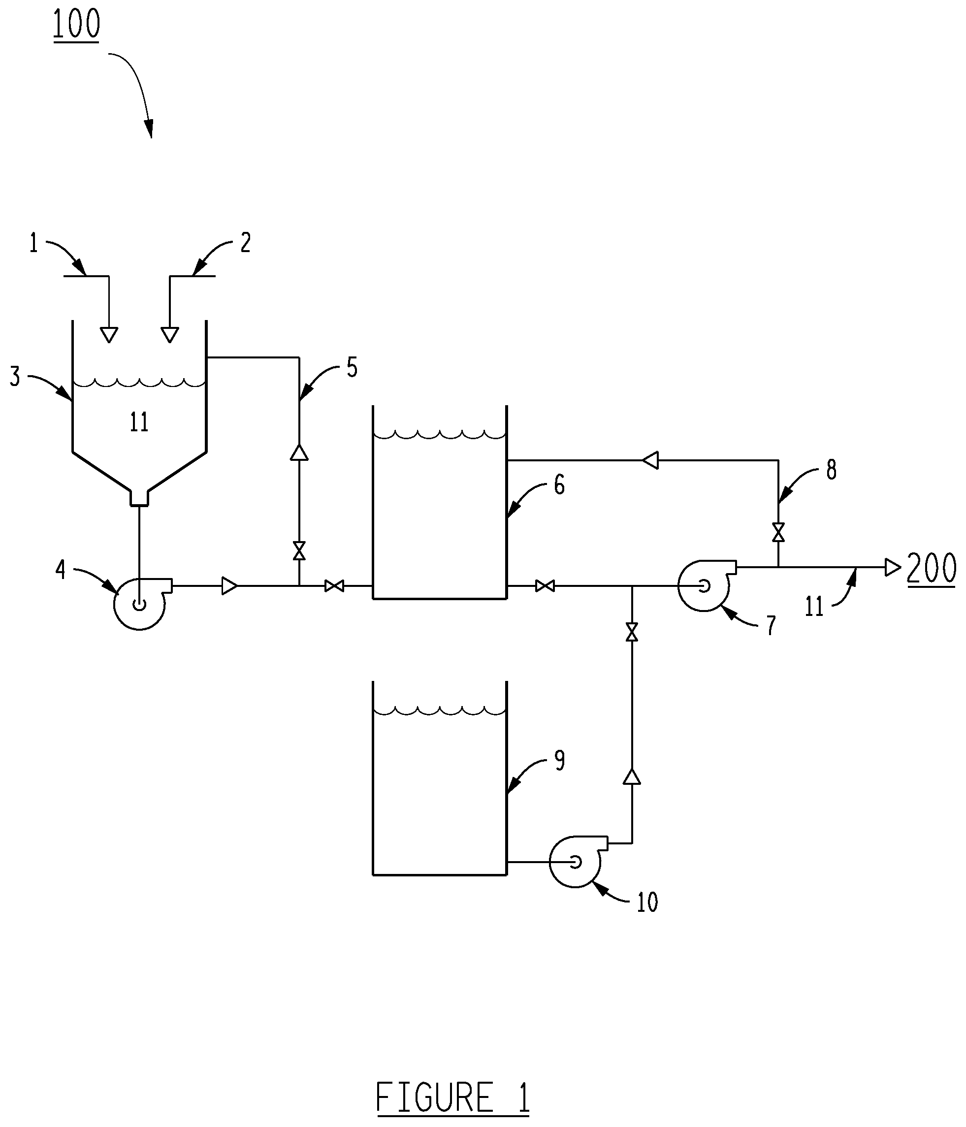
The present disclosure relates generally to a method and apparatus for reducing emissions of nitrogen oxides (NOx) from a combustion source. More particularly, to injecting a urea solution directly into the flue gas stream of a coal-fired power plant that utilizes Selective Catalytic Reduction (SCR) to lower NOxemissions. This invention herein eliminates the vast equipment, risks of using anhydrous ammonia, and costs associated with using aqueous ammonia, or complicated systems to hydrolyze urea, before injection. One process for lowering NOxemissions is SCR, which involves chemically converting NOxto elemental nitrogen by injecting a reagent, often anhydrous ammonia, aqueous ammonia, or aqueous urea. The following equations describe SCR with urea as the reagent: The prior art contains various methods of SCR in combustion sources such as diesel engines, natural gas power plants, and solid fuel combustion units, for example utility boilers. Prior to the invention herein, a successful direct injection of aqueous urea (DIAU) for SCR has been achieved in diesel engines and natural gas turbines, but not solid fuel combustion units. Diesel engines have relatively small ducts and therefore do not face the same mixing issues as solid fuel combustion units. Diesel engines and natural gas turbines have relatively low NOxlevels compared to coal-fired units as well. Reagents include aqueous ammonia (U.S. Pat. No. 3,900,554), a mixture of Na2CO3and urea (U.S. Pat. No. 4,844,915), a mixture of aqueous urea and a hydrocarbon above 1,600 degrees F. (U.S. Pat. No. 4,719,092), aqueous urea in a hydroxylic solvent above 1,300 degrees F. (U.S. Pat. No. 4,208,386), aqueous urea, but only into a natural gas power plant (UMICORE Catalyst USA, LLC at Reinhold Environmental Conference, February 2018), a mixture of ammonia and urea in a gas stream of 800 degrees C. to 1,000 degrees C. (U.S. Pat. No. 5,399,326), and aqueous ammonia or urea and a gas (U.S. Pat. No. 5,478.542). Others have used various means such as bypass ducts to convert ammonia to urea (U.S. Pat. No. 7,090,810) or slip streams (U.S. Pat. No. 8,815,197) in which to inject aqueous urea. Aqueous urea, however, is preferred as a sole reagent for SCR because unlike ammonia it is safe and easier to handle. Nevertheless, the injection of urea has historically required complex and expensive decomposition means to convert the aqueous urea to ammonia gas before injection. The direct injection of urea through an ammonia injection grid (“AIG” or “grid”) has been historically unsuccessful due to formation of deposits in the grid, which plug the grid. In fact, prior art states that the “direct injection of aqueous urea through a grid has generally not been practical due to the formation of deposits in the grid from the incomplete decomposition of urea in the gird” (U.S. Pat. No. 8,815,196). Difficulties also stem from the need to vaporize the urea before it hits the walls of the duct to prevent corrosion of the duct, and from difficulties associated with utilizing a DIAU at low load and low gas temperatures. This led to attempts to inject at the walls of the duct, which have only been successful on small SCR applications such as diesel engines. This is because of insufficient distribution of the urea, in solid fuel combustion units, into the full flue gas flow and thus insufficient decomposition of the urea to ammonia before reaching the SCR catalyst. The stratification of the NOxin the flue gas that occurs before injection causes a lack of sufficient mixing when the ammonia (after the urea is converted to ammonia) reacts with it, meaning uniform distribution of ammonia at the SCR catalyst is not established and catalysis is inefficient. The urea to ammonia conversion processes in solid fuel combustion units in the prior art are also costly to maintain and can use large amounts of high energy steam. Extensive ammonia vapor piping used also presents safety concerns due to high risk of ammonia leaking from the piping. On the contrary, a DIAU is extremely safe. For all the aforementioned reasons among others, the prior art lacks a successful DIAU into a solid fuel combustion unit. The disclosure herein contains a method and apparatus for a direct injection of urea into such a unit, the flue gas stream of a coal-fired power plant, avoiding all of the aforementioned expense and safety concerns. It is an object of the present invention to provide a system and method for a DIAU into a solid fuel combustion unit, such as the duct of a coal-fired power plant comprising a furnace, in order to lower NOxemissions via SCR. The disclosure herein eliminates the aforementioned plugging, distribution, and decomposition issues experienced, while providing for a system without use of ammonia thus avoiding its intricate handling necessities and safety risks. Injection occurs downstream of the economizer, at a lower temperature range. Adequate mixing of the flue gas stream, and of the urea injected within the flue gas stream, is critical to achieving efficient conversion of decomposition of the urea to ammonia before reaching the SCR catalyst. The stratification of the NOxin the flue gas that occurs before injection causes a lack of sufficient mixing when the ammonia (after the urea is converted to ammonia) reacts with it, meaning uniform distribution of ammonia at the SCR catalyst is not established and catalysis is inefficient. A preferred embodiment disclosed herein allows for the achievement of adequate mixing due to the arrangement of turbulence producing devices in the duct. However, other arrangements could also achieve adequate mixing and thus have adequate distribution of ammonia at the SCR catalyst. Another essential component of the preferred embodiment is an atomizing urea solution injection nozzle at the end of a lance, the lance comprising an inner pipe within a larger outer pipe. Blanketing air is supplied in between the two pipes of the lance. This maintains the exterior cleanliness of the attached nozzle and maintains the temperature of the urea solution before it is injected, thereby preventing the urea solution from scaling (precipitating out of solution) but still allowing the urea to vaporize before reaching the duct walls. The minimum required pressure of the blanketing air is above the pressure of the flue gas. The preferred embodiment has significantly fewer nozzles than AIG systems, also decreasing opportunities for plugging. These features allow for a safe DIAU using a much simpler system lacking an AIG, involved piping, and bypass ducts. The following detailed description of the preferred embodiments in conjunction with the drawings and claims elucidates these and other features of the present application. The accompanying drawings, which are included to provide a further understanding of the disclosure and are incorporated in and constitute a part of this specification, illustrate embodiments of the disclosure and together with the description serve to explain the principles of the disclosure. In the drawings: A recirculation line (5) and mix tank pump (4) aid with mixing of the urea solution (11) in urea solution mix tank (3). A flushing pump (10) is preferred to flush out system (100). A urea solution pump (7) supplies urea solution (11) to system (200). A urea solution recirculation line (8) protects the urea solution pump (7). This injection occurs after flue gas (12) has been passed over first turbulence producing device, (14) and (15), to generate adequate mixing of the flue gas (12). Other arrangements of turbulence producing devices can suffice, as long as adequate mixing results. The urea solution (11) is injected via a urea solution injection nozzle with a lance further comprising an outer larger pipe and a smaller inner pipe at the end (17). Blanketing air (22) having a velocity equal to that of urea solution (11) to be injected travels through lance (17), between the two pipes of lance (17), to maintain the cleanliness of the tip of the lance's nozzle. This also prevents urea solution (11) from scaling (precipitating) on the inner pipe of lance (17), thereby preventing plugging. Blanketing air (22) must be above the pressure of flue gas (12). Once urea solution (11) enters flue gas duct (13), the thermal energy of flue gas duct (13) heats the urea solution to a temperature adequate for the catalysis reaction using a SCR (20). The preferred embodiment contains one nozzle per 50-100 megawatts (MW) of generation, as well as flow rate of 0.25 gallons per minute to 1.5 gallons per minute, which also prevents plugging due to the increased flow through fewer nozzles. An opening of 0.05 inches to 0.1 inches per nozzle is preferred for minimal plugging. Proximate to lance (17) is a second turbulence producing device, (16) and (18), which provides for adequate mixing of urea solution (11) in flue gas (12). Turning vanes (19) also help reduce pressure drop and help provide even distribution before the SCR (20). Other arrangements of turbulence producing devices can suffice, as long as adequate mixing results. The urea solution (11) is converted to ammonia using only the heat in the flue gas duct (13). Then the flue gas, comprising ammonia, reaches SCR (20), where NOxis reduced, and the flue gas (12) and its components are ultimately discharged to the atmosphere (21). Experimental Data Data from a continuous emissions monitoring system (CEMS) supports the conclusion that there is a 3% increase in process efficiency, resulting in the same NO, removal rate using less urea as the prior ammonia system. The 3% increase in efficiency may be due to blow down that occurred in the prior ammonia system, as the DIAU disclosed herein has no blow down. This disclosure provides an apparatus and method for reducing emissions of nitrogen oxides (NOx) from a combustion source. For example, a method and apparatus for injecting a urea solution directly into the flue gas stream of a coal-fired power plant that utilizes Selective Catalytic Reduction (SCR) to lower NOx emissions. 1. A method for reducing the concentration of at least one predetermined chemical constituent comprising:
selecting the at least one predetermined chemical constituent for removal from an exhaust gas stream produced by combustion of a solid fuel and having a thermal energy component and a pressure; passing the exhaust gas stream through a first turbulence producing device so as to distribute the predetermined chemical constituent throughout the exhaust gas stream, injecting into the exhaust gas stream, at an injection location and via at least one atomizing nozzle proximate to a second turbulence producing device, at least one reagent selected to facilitate the removal of the at least one predetermined chemical constituent; converting the at least one reagent to a first reaction by-product, utilizing substantially only the thermal energy present in the exhaust gas stream; passing the exhaust gas stream through the second turbulence producing device so as to distribute the first reaction by-product and the predetermined chemical constituent substantially uniformly throughout the exhaust gas stream; and reacting the at least one predetermined chemical constituent with the first reaction by-product, converting the predetermined chemical constituent to a second reaction by-product, thereby reducing the concentration of the chemical constituent in the exhaust gas stream. 2. The method according to 3. The method according to 4. The method according to 5. The method according to 6. The method according to 7. The method according to 8. An apparatus for reducing the concentration of at least one predetermined chemical constituent comprising:
a solid fuel combustion unit further comprising a furnace; a first turbulence producing device downstream of the furnace and configured to distribute the at least one predetermined chemical constituent substantially homogenously throughout a gas stream produced by the solid fuel combustion unit; at least one atomizing nozzle to inject a reagent at an injection location into the gas stream; and a second turbulence producing device in proximity to the at least one atomizing nozzle, wherein the second turbulence producing device is configured to distribute a first reaction by-product and the predetermined chemical constituent substantially uniformly throughout the gas stream. 9. The apparatus according to 10. The apparatus according to 11. The apparatus according to 12. The apparatus according to 13. A method for reducing the concentration of at least one predetermined chemical constituent which comprises the steps of:
generating a gas stream utilizing a solid fuel combustion unit wherein the gas stream comprises a thermal energy component, a pressure component, and the at least one predetermined chemical constituent; selecting at least one reagent, such reagent selected to facilitate the removal of the at least one predetermined chemical constituent from the gas stream; passing the gas stream through a first turbulence producing device so as to distribute the predetermined chemical constituent throughout the gas stream, injecting into the gas stream, at an injection location and via at least one atomizing nozzle proximate to a second turbulence producing device, the at least one reagent selected to facilitate the removal of the at least one predetermined chemical constituent; converting the at least one reagent to a first reaction by-product, utilizing substantially only the thermal energy present in the gas stream; passing the gas stream through the second turbulence producing device so as to distribute the first reaction by-product and the predetermined chemical constituent substantially uniformly throughout the gas stream; and reacting the at least one predetermined chemical constituent with the first reaction by-product, converting the predetermined chemical constituent to a second reaction by-product, thereby reducing the concentration of the chemical constituent in the exhaust gas stream. 14. The method according to 15. The method according to 16. The method according to 17. The method according to 18. The method according to 19. The method according to BACKGROUND OF THE INVENTION
1. Field of the Invention
2. Description of the Related Art
(NH2)2CO+H2O→2NH3+CO2 Eq. 1:
2NO+2NH3+½O2→3H2O and tm Eq. 2:
3NO2+4NH3→3½N2+6H2O Eq. 3:BRIEF SUMMARY OF THE INVENTION
BRIEF DESCRIPTION OF THE DRAWINGS
DETAILED DESCRIPTION OF THE INVENTION