HEAT EXCHANGER
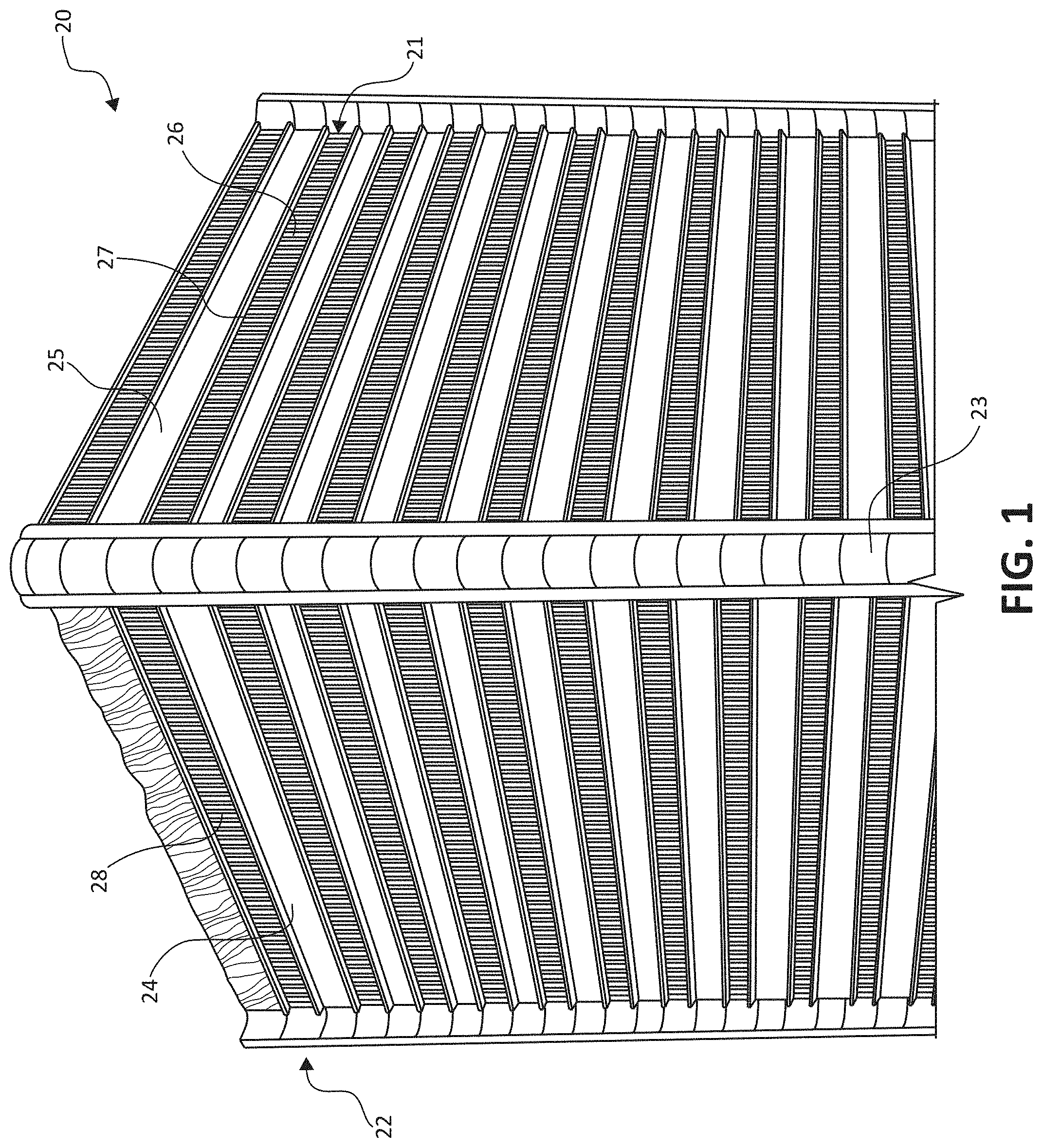
The present disclosure relates to heat exchangers. An environmental control system (ECS), such as an aircraft ECS, may include one or more heat exchangers. Such heat exchangers may be of the fluid-to-fluid type, either gas or liquid, and may include a core assembly including alternating rows of heat transfer fins and plates. The rows are interposed to create multiple hot and cold side passageways extending through the core assembly. The passageways may create a counter-flow, parallel flow, or cross-flow heat exchange relationship between fluids flowing through the passageways. During operation, heat is exchanged between the fluids flowing through the core assembly. Because an aircraft ECS often operates at, and generates within itself, relatively extreme temperature and pressure conditions, the heat exchanger may be subjected to the adverse effects of temperatures as well as the forces generated by operation of the aircraft. In some examples, the disclosure relates to a plate fin heat exchanger, and a method of making a plate fin heat exchanger. The plate fin heat exchanger may include a heat exchanger core defining hot and cold passages, e.g., alternating between hot and cold passage in a stacked configuration. The stacked hot and cold passages of the core may be separated by tube sheets. The respective hot passage and cold passage may have frames defining the lateral sides of the passages. One or more corners of the heat exchanger core defined by the frames may be shaped corners, e.g., corners defining respective non-square shapes. In some examples, one or more portions of the hot frame and/or cold frames may be configured to the removed from the assembly (e.g., after brazing of the components of the heat exchanger core). In some examples, the hot frame and cold frames may include portions that, when assembled, define flow manifolds into and/or out of the hot and cold passages, respectively. In one aspect, the disclosure relates to a plate fin heat exchanger. The heat exchanger assembly comprises a cold passage defined by a cold frame; a hot passage defined by a hot frame; a tube sheet between the cold passage and the hot passage; a top side plate; and a bottom side plate, wherein the cold passage, the tube sheet, and the hot passage are between the top side plate and the bottom side plate, wherein the cold frame includes a first bar and a second bar attached at a corner of the heat exchanger, wherein at least a portion of the first bar is configured to be removed from the cold frame, wherein the hot frame includes a third bar and a fourth bar attached at the corner of the heat exchanger, wherein at least a portion of the third bar is configured to be removed from the hot frame, and wherein the corner of the heat exchanger defined by at least one of the hot frame or the cold frame has a non-square shape. In another aspect, the disclosure relates to a method for making a plate fin heat exchanger. The method comprises assembling a cold frame, a hot frame, a tube sheet, a top sheet, and a bottom sheet in a stacked configuration; attaching the cold frame, the hot frame, the tube sheet, the top sheet, and the bottom sheet to each other in the stacked configuration, wherein, in the stacked configuration, the cold frame defines a cold passage, the hot frame defines a hot passage, wherein, in the stacked configuration, the tube sheet is between the hot frame and the cold frame, wherein the cold frame includes a first bar and a second bar attached at a corner of the heat exchanger, wherein the hot frame includes a third bar and a fourth bar attached at the corner of the heat exchanger, and wherein the corner of the heat exchanger defined by at least one of the hot frame or the cold frame has a non-square shape; and removing at least a portion of the first bar from the cold frame and at least a portion of the third bar from the hot frame. In another aspect, the disclosure relates to a plate fin heat exchanger comprising a cold passage defined by a cold frame; a hot passage defined by a hot frame; a tube sheet between the cold passage and the hot passage; a top side plate; and a bottom side plate, wherein the cold passage, the tube sheet, and the hot passage are between the top side plate and the bottom side plate, wherein the cold frame includes a first pair of bars defining the cold passage, a second pair of bars defining cold flow manifolds, and a third pairs of bars defining hot flow manifolds, wherein the hot frame includes a fourth pair of bars defining the hot passage, a fifth pair of bars defining the hot flow manifolds, and a sixth pairs of bars defining the cold flow manifolds, and wherein a corner of the heat exchanger defined by at least one of the hot frame or the cold frame has a non-square shape. In another aspect, the disclosure relates to a method for making a plate fin heat exchanger. The method comprises: assembling a cold frame, a hot frame, a tube sheet, a top sheet, and a bottom sheet in a stacked configuration; attaching the cold frame, the hot frame, the tube sheet, the top sheet, and the bottom sheet to each other in the stacked configuration, wherein, in the stacked configuration, the cold frame defines a cold passage, the hot frame defines a hot passage, the tube sheet is between the hot frame and the cold frame, and the cold passage, the tube sheet, and the hot passage are between the top side plate and the bottom side plate, wherein the cold frame includes a first pair of bars defining the cold passage, a second pair of bars defining cold flow manifolds, and a third pairs of bars defining hot flow manifolds, wherein the hot frame includes a fourth pair of bars defining the hot passage, a fifth pair of bars defining the hot flow manifolds, and a sixth pairs of bars defining the cold flow manifolds, and wherein a corner of the heat exchanger defined by at least one of the hot frame or the cold frame has a non-square shape. This summary is intended to provide an overview of the subject matter described in this disclosure. It is not intended to provide an exclusive or exhaustive explanation of the systems, devices, and methods described in detail within the accompanying drawings and description below. Further details of one or more examples are set forth in the accompanying drawings and the description below. Other features, objects, and advantages will be apparent from the description and drawings, and from the statements provided below. In some examples, the disclosure describes plate fin heat exchangers and techniques for making such heat exchangers. Plate fin heat exchanger may be employed in a variety of applications, such as, but not limited to, in an ECS of an aircraft. In some examples, a plate fin heat exchanger may be manufactured by stacking the heat exchanger core components, e.g., cold and hot passage frames, fins, tube sheets, top and bottom side plates, in a tooling fixture. The core component stack inserted in the tooling fixture may start with a bottom side plate as the base, then a tube sheet may be added, followed by the addition of a hot frame and fins of a “hot” passage (e.g., a passageway in which relatively hot fluid may flow during operation of the heat exchanger), followed by the addition of another tube sheet on the hot frame and fins, and then followed by the addition a cold frame and fins of a “cold” passage (e.g., a passageway in which relatively cold fluid may flow during operation of the heat exchanger). The process of forming alternating layers of hot passage components and cold passage components separated by tube sheets may be repeated until the desired number of hot and cold passages are achieved. A top side plate similar or identical to the bottom side plate may then be added on the top of the stack in the fixture. The stack of core components may then be heated in a brazing furnace to achieve the brazing of the core components to each other. Once the core component stack is completed and brazed, inlet and outlet heat exchanger pans, which form part of the outer shell of the heat exchanger, may be welded to the core components. In some examples, the corners of the core components may have linear, square corners (defining a 90 degree angle at the corners). In accordance with some examples of the disclosure, a plate fin heat exchanger core may have one or more shaped corners. As used herein, a shaped corner may refer to a corner having a shape other than that of the square corners shown in The shaped corner(s) of the heat exchanger core may be defined at least in part by the frames of the hot and cold passages. In some examples, each corner of the heat exchanger core may be a shaped corner (e.g., all four corners of a square shaped heat exchanger), while in other examples some but not all of the corners may be shaped with the other corners by square corners. In some examples, the shaped corners may extend substantially the entire height (measured in the stacking direction of the hot and cold frames) of the heat exchanger core (e.g., where each hot passage frame and cold passage frame in the stack has a shape at the corresponding corner) while in other examples, the shape corner may only extend a portion of the height (e.g., with some cold frames and/or hot frames having a shape at the corresponding corner while other cold frames and/or hot frames in the stack having square corners at the same corner). A shaped corner may have any suitable shape that does not constitute a linear, 90 degree angle corner such as that shown in In some examples, one or more portions of the hot frame and/or cold frames of a heat exchanger core with one or more shaped corners may be configured to be removed from the assembly (e.g., after brazing of the components of the heat exchanger core). For examples, as described further below, a hot frame and/or cold frame may initially include one or more support bars and/or side bars in addition to one or more main bars. In some examples, once the heat exchanger core components have been brazed together, the support bar(s) and/or side bar(s) may be removed from the hot and cold frames, e.g, to open up the hot and cold flow paths, respectively. The support bar(s) and/or side bar(s) may assist in keeping all passages aligned and supported at all sides while the whole stack of core components are compressed and brazed. This may prevent distortion and fins collapsing while also aiding in reducing the gaps between respective layers of the core, e.g., since more pressure can be applied with the support bar(s) and/or side bar(s) present. Additionally, the support bar(s) and/or side bar(s) may provide extra material to form any shape for corners or in-between separators for more than two flow paths. In some examples, the hot frame and cold frames of a heat exchanger core with one or more shaped corners may include portions that, when assembled, define flow manifolds into and/or out of the hot and cold passages, respectively. The shaped corners of a heat exchanger may provide one or more benefits, including any combination of the benefits described herein. For example, the shaped corner(s) may be function as a supporting and/or mounting area for bracket, tubes, pins, or any holding mechanisms. In some examples, the shaped corner(s) may be used as an additional fluid flow circuit for the heat exchanger. The shaped corner(s) may have a shape/form that may serve as a guide to assemble pans, ducts and frames, and the like for a heat exchanger assembly. The shaped corners may serve to install (e.g., attach or otherwise position) the core inside a three-dimensional (3D) printed or otherwise preformed shell. The shaped corners may be extended and oriented from frame to give the desired direction of fluid flow either or both when the fluid enters or exits the heat exchanger core. The shaped corners may absorb core size variation for assembly component attachment. The shaped corners may provide a relatively smooth flow transition in the heat exchanger to prevent pressure losses. The shaped corners may function as a stiffener element for heat exchanger strength purposes. The shaped corners may be used as a mounting machined surface for bolts, inserts, tubes, hoses and the like. The shaped corners can be machined as guides for heat exchanger assembly. The shaped corners can be used as identification and/or traceability elements in the heat exchanger. The shaped corners may be used as a pivoting element for thermal growth. The shaped corners may be used as hoisting element for packaging/installation purposes. The shaped corners can be used as a structural pillar to support relatively heavy loads. The shaped corners can be used for ducting/tubing purposes, e.g., to replace external components. Core components 20 includes a plurality of tube sheets 27 (only an individual tube sheet is labelled in Heat exchanger core 30 may be similar to heat exchanger core 20 in The heat exchanger core 30 may generally be constructed in a stacked, plate fin design. Top side plate 36 may be on one side of the core 30 and bottom side plate 37 may be on an opposite side of the core 30. Reference to “top,” “bottom,” and “sides” is for ease of description only and is not intended to limit the orientation of heat exchanger core 30 in operation. Between top and bottom plates 36, 37, hot passage 21 may run generally perpendicular to second or cold passage 22. Tube sheet 27 is interposed between hot and cold passages 21, 22. The outer perimeter configuration of tube sheet 27 may match a combined perimeter configuration of both hot and cold frames 24, 25 described below. In some examples, hot frame 24 may frame or at least partially surround the perimeter of hot passages 21. Hot fins 26 are located between hot frame 24 on the lateral sides and top side plate 36 and tube sheet 27 on top and bottom, respectively. Cold frame 25, similar in design and construction to the hot frame 24, may frame or at least partially surround the perimeter of cold passages 22. Cold fins 28 are located between cold frame 25 on the lateral sides and tube sheet 27 and bottom plate 37 on top and bottom. Corner 38 of the core 30 may extend from a corner of top plate 36, through the frames 24, 25, and to a corner of bottom plate 37. Corner 23 may correspond to a corner of core 20, such as, corner 23 in When heat exchanger core 30 shown in Similarly, the adjacent layer directly on “top” of this “bottom” layer of core 30 may form hot fluid passage 21 bounded by top plate 36 on “top,” tube sheet 27 on “bottom” and hot frame 24 on the “sides.” As will be described in further detail below, in some examples, at least a portion of two bars on opposing sides of hot frame 24 may be removed to form openings that allow for fluid flow across hot passage 21. Hot fins 26 are located within hot passage 21 between hot frame 24, and may define the spacing between tube sheet 27 and top plate 36. As shown, heat exchanger core 30 includes multiple layers which define alternating cold and hot passages 22, 21. During operation, a relatively cold fluid (e.g., cold air) may flow into heat exchanger core 30 via a cold intake manifold, through cold passage 22 and out via a cold outlet manifold. Likewise, a relatively hot fluid (e.g., hot air) may flow into heat exchanger core 30 via a hot intake manifold, through hot passage 21 and out via a hot outlet manifold. In this manner, heat from the hot fluid within hot passage 21 is transferred to the cold fluid within the adjacent cold passage 22. Hot fins 26 and cold fins 28 form a secondary surface for heat transfer during operation to remove heat from the fluid within the hot passage 21. The tube sheets, enclosure bars, and fins of heat exchangers described herein may be formed of any suitable material. For example, the top plate, bottom plate, tube sheets, frames, and/or fins may be aluminum, copper, iron, stainless steel, nickel based alloy (e.g., Inconel), titanium components, or any combination thereof, although other materials are contemplated. In some examples, all the components of a heat exchangers may be made from the same material. For example, an aluminum heat exchanger may have parts such as the tube sheets, enclosure bars, and fins made from aluminum (e.g., along with the outer shell). Likewise, a stainless steel heat exchanger may have parts such as the tube sheets, enclosure bars, and fins made from stainless steel (e.g., along with the outer shell). The frames, including frames with one or more shaped corners, may be produced via extrusion, machining, and/or additive manufacturing. A braze material for joining the parts may be selected based on the composition of the parts being joined. The hot and cold fluid passageways (e.g., passages 21 and 22) are shown as extending approximately ninety degrees (90°) to each other, forming a cross-flow condition between fluids flowing through core components 16. However, in other examples, the fluid passageways may extend approximately parallel to each other, creating a parallel-flow condition between the fluids. Alternatively, the fluid passageways may extend in opposite directions to each other, creating a counter-flow condition between the fluids. Frame 40 may include, at a perimeter thereof, a pair of main bars 41 With the support bars 42 In some examples, frame 40 may further include a pair of side bars 43 In some examples, all or a portion of support bars 42 Frame 40 includes corners 38 Rather being a square corner, corners 38 Side plate 50 may include a side or perimeter edge 51. Corners 54 Side plate 50 may further include cut line 53 that extends along all or a portion of perimeter edge 51. Cut line 53 may correspond to the location of one or more of the grooves 45 In the configuration shown in Likewise, a side bar has been cut away from a hot frame 75 to define hot passage 71. Hot passage 71 is open to air entering or existing the passage 71 because of the side bar removal. However, main bar 75 Similarly, The stack of component may then be brazed to attach the components to each other (82). Any suitable brazing technique may be used. During brazing, one or more slots, such as, slots 44 Once the stack of components are brazed, then a portion of side bars 43 As described herein, in some examples, one or more corners of a heat exchanger core may constitute shaped corners. The one or more shaped corners may be provided for a desired functionality. In some examples, after the covers are removed pans, flanges, or any next lever component may be welded. The curvilinear corners may provide extra faying surface to eliminate alignments/sizes variance from both heat exchanger core and pans. The curvilinear corners may also aid to keep the resulting heat from welding away from fins that can potentially burned away reducing heat transfer performance In some examples, flow circuits may be defined by the combination of apertures 89 in curvilinear corners 78 of hot frame 75 and cold frame 74. For example, the flow circuits may be used for extra heat circuits (reflow) or fresh flow to either heat or cold electronics, chilled water, oil, fuel, air, and the like. Curvilinear corners are just one example of a shaped corner that may be employed in some examples of the disclosure. Outer shell 91 is configured to surround the heat exchanger core and defines a cold flow manifold 92 (e.g., inlet manifold or outlet manifold) into cold passage 72 and a hot flow manifold 93 (e.g., inlet manifold or outlet manifold) into hot passage 71. In some examples, outer shell 91 may be fabricated separate from heat exchanger core 70, e.g., using additive manufacturing (3-dimensional printing) techniques. Outer shell 91 may be subsequently attached to heat exchanger core 70, e.g., by mating outer shell 91 with shaped corner 78. In some examples, a glue or other adhesive may be applied to further join outer shell 91 to shaped corner 78, e.g., in apertures in outer shell 91 distributed between top and bottom plate 36, 37 of core 70. As described above, in some examples, one or more portions of a hot frame and a cold frame of a heat exchange core may also define flow manifolds into and/or out of the hot passage(s) and cold passage(s) of a heat exchange core. Like the example heat exchangers described above in which portions of the hot frame and cold frames are removable, e.g., after brazing, such example heat exchanger may have corners that constitute shaped corners. Heat exchanger 100 includes a top plate 136, outer shell 192, cold flow inlet 102, cold flow outlet 104, hot flow inlet 108, and hot flow outlet 106. Heat exchanger 100 may function similar to that of, e.g., heat exchanger 20 in that heat exchanger 100 includes at least one cold passage 122 defined in part by a cold frame 125 (e.g., where cold fins are located in the cold passage between the cold frame) and at least one hot passage 121 defined in part by a hot frame 124 (e.g., where hot fins are located in the hot passage between the hot frame). A relatively cold fluid is directed into cold flow inlet 102 of heat exchanger 100 where is flows through the various cold passages (e.g., cold passage 122 in Hot frame 124 and cold frame 125 each include main bars 141 For example, when stacked and brazed, manifold bars 143 As shown, heat exchanger 100 includes shaped corners 138 As another example, corners 138 As another example, corners 138 As another example, corners 138 As another example, corners 138 As another example, corner 138 As described herein, example heat exchangers of the disclosure may include one or more shaped corners, e.g., at the intersection of respective ends hot and cold frames. In some examples, the shaped corner(s) may provide one or more advantages. For example, such a design concept may enable multiple corner shapes or other configurations that may be used to improve manufacturing for assembly interfaces and may provide new design alternatives for heat exchangers assemblies. For example, the shaped corners may be utilized as an installation reference or guide for welding or machining next assembly components such as ducts, pans, frames, brackets, mounts, and the like. In some examples, shaped corners may be designed to provide integral mounting points within the heat exchanger core, and also to provide extra stiffness if desired. In some examples, shaped corners may help to prevent dimensional variations due to brazing and heat treatment processes, thereby aiding the manufacturing process. In some examples, the shaped corners may reduce heat exchanger core stacking complexity and cycle time by proving stacking reference points along with the box-bar frame design. In some examples, the shaped corners may simplify heat exchanger core fit up for next assembly process when machining is desired. In some examples, along with box-bar frames concept, shape corners may prevent passages collapsing during brazing, welding and heat treating. In some examples, shaped corners may be also contribute to the function of the heat exchanger function. For example, the shaped corners may be used to embed additional flow circuits for any fluid, e.g., at the corners of the heat exchanger. As another example, the shaped corners may provide additional heat exchanger core stiffness. In some examples, the shaped corners may substantially eliminate the deformation of core heat exchanger, e.g., caused from welding process may be associated with butterpass designs (e.g., a process including adding material by welding/melting base material at each corner and adding filler material (e.g., a welding rod) where the resulting corner is not smooth or does not provide a desirable mounting surface for next assembly). In some examples, the shaped corners may improve overall heat exchanger assembly cycle time. Various examples have been described. These and other examples are within the scope of the following claims and clauses. Clause 1. A plate fin heat exchanger comprising: a cold passage defined by a cold frame; a hot passage defined by a hot frame; a tube sheet between the cold passage and the hot passage; a top side plate; and a bottom side plate, wherein the cold passage, the tube sheet, and the hot passage are between the top side plate and the bottom side plate, wherein the cold frame includes a first bar and a second bar attached at a corner of the heat exchanger, wherein at least a portion of the first bar is configured to be removed from the cold frame, wherein the hot frame includes a third bar and a fourth bar attached at the corner of the heat exchanger, wherein at least a portion of the third bar is configured to be removed from the hot frame, and wherein the corner of the heat exchanger defined by at least one of the hot frame or the cold frame has a non-square shape. Clause 2. The heat exchanger of clause 1, wherein the corner of the heat exchanger has a curvilinear shape. Clause 3. The heat exchanger of any one of clauses 1 or 2, further comprising a pan attached to the corner of the heat exchanger, wherein the pan defines a flow manifold fluidically coupled to one of the hot passage or the cold passage. Clause 4. The heat exchanger of any one of clauses 1-4, wherein the corner of the heat exchanger defines an internal passage extending from the top side plate to the bottom side plate. Clause 5. The heat exchanger of any one of clauses 1-4, wherein the corner of the heat exchanger defines a mount for the heat exchanger. Clause 6. The heat exchanger of any one of clauses 1-5, further comprising an outer shell configured to define a first flow manifold into the hot passage and a second flow manifold into the cold passage, and wherein the outer shell is configured to mate with the corner to attach the outer shell to the corner. Clause 7. The heat exchanger of any one of clauses 1-6, wherein the hot frame and cold frame are attached to each other via one or more braze joints. Clause 8. The heat exchanger of any one of clauses 1-7, further comprising: hot fins between the hot frame in the hot passage; and cold fins between the cold frame in the cold passage. Clause 9. A method for making a plate fin heat exchanger, the method comprising: assembling a cold frame, a hot frame, a tube sheet, a top sheet, and a bottom sheet in a stacked configuration; attaching the cold frame, the hot frame, the tube sheet, the top sheet, and the bottom sheet to each other in the stacked configuration, wherein, in the stacked configuration, the cold frame defines a cold passage, the hot frame defines a hot passage, wherein, in the stacked configuration, the tube sheet is between the hot frame and the cold frame, wherein the cold frame includes a first bar and a second bar attached at a corner of the heat exchanger, wherein the hot frame includes a third bar and a fourth bar attached at the corner of the heat exchanger, and wherein the corner of the heat exchanger defined by at least one of the hot frame or the cold frame has a non-square shape; and removing at least a portion of the first bar from the cold frame and at least a portion of the third bar from the hot frame. Clause 10. The method of clause 9, wherein attaching the cold frame, the hot frame, the tube sheet, the top sheet, and the bottom sheet to each other in the stacked configuration comprises brazing the cold frame, the hot frame, the tube sheet, the top sheet, and the bottom sheet to each other in the stacked configuration. Clause 11. The method of any one of clauses 9 or 10, wherein the corner of the heat exchanger has a curvilinear shape. Clause 12. The method of any one of clauses 9-11, further comprising attaching a pan to the corner of the heat exchanger, wherein the pan defines a flow manifold fluidically coupled to one of the hot passage or the cold passage. Clause 13. The method of any one of clauses 9-12, wherein the corner of the heat exchanger defines an internal passage extending from the top side plate to the bottom side plate. Clause 14. The method of any one of clauses 9-13, further comprising mounting the heat exchanger to another member via the corner. Clause 15. The method of any one of clauses 9-14, further comprising mating an outer shell to the corner to attach the outer shell to the corner, wherein the outer shell is configured to define a first flow manifold into the hot passage and a second flow manifold into the cold passage. Clause 16. The method of any one of clauses 9-15, further comprising placing hot fins between the hot frame in the hot passage, and placing cold fins between the cold frame in the cold passage. Clause 17. A plate fin heat exchanger comprising: a cold passage defined by a cold frame; a hot passage defined by a hot frame; a tube sheet between the cold passage and the hot passage; a top side plate; and a bottom side plate, wherein the cold passage, the tube sheet, and the hot passage are between the top side plate and the bottom side plate, wherein the cold frame includes a first pair of bars defining the cold passage, a second pair of bars defining cold flow manifolds, and a third pairs of bars defining hot flow manifolds, wherein the hot frame includes a fourth pair of bars defining the hot passage, a fifth pair of bars defining the hot flow manifolds, and a sixth pairs of bars defining the cold flow manifolds, and wherein a corner of the heat exchanger defined by at least one of the hot frame or the cold frame has a non-square shape. Clause 18. The heat exchanger of clause 17, wherein the corner of the heat exchanger has a curvilinear shape. Clause 19. The heat exchanger of any one of clauses 17 or 18, wherein the corner of the heat exchanger defines an internal passage extending from the top side plate to the bottom side plate. Clause 20. The heat exchanger of any one of clauses 17-19, wherein the corner of the heat exchanger defines a mount for the heat exchanger. Clause 21. The heat exchanger of any one of clauses 17-20, wherein the hot frame and cold frames are attached to each other via one or more braze joints. Clause 22. A method for making a plate fin heat exchanger, the method comprising: assembling a cold frame, a hot frame, a tube sheet, a top sheet, and a bottom sheet in a stacked configuration; attaching the cold frame, the hot frame, the tube sheet, the top sheet, and the bottom sheet to each other in the stacked configuration, wherein, in the stacked configuration, the cold frame defines a cold passage, the hot frame defines a hot passage, the tube sheet is between the hot frame and the cold frame, and the cold passage, the tube sheet, and the hot passage are between the top side plate and the bottom side plate, wherein the cold frame includes a first pair of bars defining the cold passage, a second pair of bars defining cold flow manifolds, and a third pairs of bars defining hot flow manifolds, wherein the hot frame includes a fourth pair of bars defining the hot passage, a fifth pair of bars defining the hot flow manifolds, and a sixth pairs of bars defining the cold flow manifolds, and wherein a corner of the heat exchanger defined by at least one of the hot frame or the cold frame has a non-square shape. Clause 23. The method of clause 22, wherein the corner of the heat exchanger has a curvilinear shape. Clause 24. The method of any one of clauses 22 or 23, wherein the corner of the heat exchanger defines an internal passage extending from the top side plate to the bottom side plate. Clause 25. The method of any one of clauses 22-24, wherein the corner of the heat exchanger defines a mount for the heat exchanger. Clause 26. The method of any one of clauses 22-25, wherein the hot frame and cold frames are attached to each other via one or more braze joints. In some examples, a plate fin heat exchanger including a cold passage defined by a cold frame; a hot passage defined by a hot frame; a tube sheet between the cold passage and the hot passage; a top side plate; and a bottom side plate, wherein the cold frame includes a first bar and a second bar attached at a corner of the heat exchanger, wherein at least a portion of the first bar is configured to be removed from the cold frame, wherein the hot frame includes a third bar and a fourth bar attached at the corner of the heat exchanger, wherein at least a portion of the third bar is configured to be removed from the hot frame, and wherein the corner of the heat exchanger defined by at least one of the hot frame or the cold frame has a non-square shape. 1. A plate fin heat exchanger comprising:
a cold passage defined by a cold frame; a hot passage defined by a hot frame; a tube sheet between the cold passage and the hot passage; a top side plate; and a bottom side plate, wherein the cold passage, the tube sheet, and the hot passage are between the top side plate and the bottom side plate, wherein the cold frame includes a first bar and a second bar attached at a corner of the heat exchanger, wherein at least a portion of the first bar is configured to be removed from the cold frame, wherein the hot frame includes a third bar and a fourth bar attached at the corner of the heat exchanger, wherein at least a portion of the third bar is configured to be removed from the hot frame, and wherein the corner of the heat exchanger defined by at least one of the hot frame or the cold frame has a non-square shape. 2. The heat exchanger of 3. The heat exchanger of 4. The heat exchanger of 5. The heat exchanger of 6. The heat exchanger of 7. The heat exchanger of 8. The heat exchanger of hot fins between the hot frame in the hot passage; and cold fins between the cold frame in the cold passage. 9. A method for making a plate fin heat exchanger, the method comprising:
assembling a cold frame, a hot frame, a tube sheet, a top sheet, and a bottom sheet in a stacked configuration; attaching the cold frame, the hot frame, the tube sheet, the top sheet, and the bottom sheet to each other in the stacked configuration, wherein, in the stacked configuration, the cold frame defines a cold passage, the hot frame defines a hot passage, wherein, in the stacked configuration, the tube sheet is between the hot frame and the cold frame, wherein the cold frame includes a first bar and a second bar attached at a corner of the heat exchanger, wherein the hot frame includes a third bar and a fourth bar attached at the corner of the heat exchanger, and wherein the corner of the heat exchanger defined by at least one of the hot frame or the cold frame has a non-square shape; and removing at least a portion of the first bar from the cold frame and at least a portion of the third bar from the hot frame. 10. The method of 11. The method of 12. The method of 13. The method of 14. The method of 15. The method of 16. The method of placing hot fins between the hot frame in the hot passage, and placing cold fins between the cold frame in the cold passage. 17. A plate fin heat exchanger comprising:
a cold passage defined by a cold frame; a hot passage defined by a hot frame; a tube sheet between the cold passage and the hot passage; a top side plate; and a bottom side plate, wherein the cold passage, the tube sheet, and the hot passage are between the top side plate and the bottom side plate, wherein the cold frame includes a first pair of bars defining the cold passage, a second pair of bars defining cold flow manifolds, and a third pairs of bars defining hot flow manifolds, wherein the hot frame includes a fourth pair of bars defining the hot passage, a fifth pair of bars defining the hot flow manifolds, and a sixth pairs of bars defining the cold flow manifolds, and wherein a corner of the heat exchanger defined by at least one of the hot frame or the cold frame has a non-square shape. 18. The heat exchanger of 19. The heat exchanger of 20. The heat exchanger of TECHNICAL FIELD
BACKGROUND
SUMMARY
BRIEF DESCRIPTION OF THE FIGURES
DETAILED DESCRIPTION