WORK MACHINE
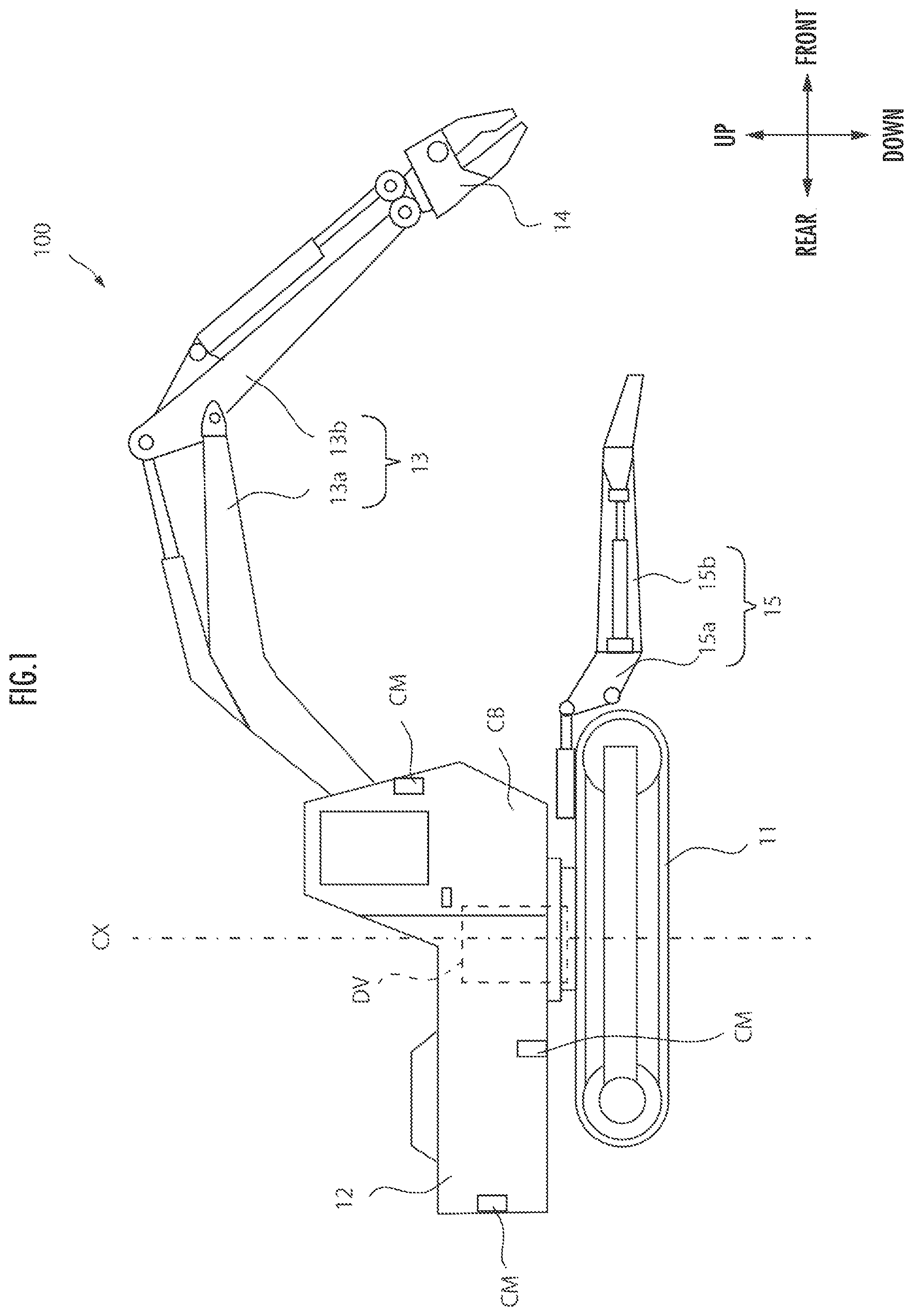
The present invention relates to a work machine such as a hydraulic excavator or a dismantling work machine dismantling a vehicle. For example, in a hydraulic excavator, an upper swivel body including an operator cab or the like is laid on a lower traveling body to be swivelable by a swivel device. One end of a boom is rotatably coupled with a front portion of the upper swivel body. One end of an arm is rotatably coupled with another end of the boom. A bucket is rotatably coupled with another end of the arm. A swiveling action of the upper swivel body and rotating actions of the boom, the arm, and the bucket are performed by operations, by an operator, of operation levers provided to the operator cab, for example. In a case of ground leveling work or the like, precision of actions of the boom, the arm, and the bucket are requested. Accordingly, Patent Literature 1 discloses that switches for adjusting speeds of rotating actions of the boom, the arm, and the bucket are provided to the operation levers (see Patent Literature 1). In an operation control method disclosed in Patent Literature 1, an operator has to adjust speeds of rotating actions of a boom, an arm, and a bucket by manually operating switches. Consequently, for example, one problem may be raised that in a case where the operator makes wrong switching of the switch, an action can be performed at a speed not intended by the operator. An object of the present invention, which has been made in consideration of the above problems in related art, is to provide a work machine that is capable of causing an action object of the work machine to act in a manner intended by an operator. A work machine of the present invention is a work machine for processing a work target object, the work machine including: a base body; a working unit which is displaceable with respect to the base body and performs a processing action on the work target object; an operation accepting unit which accepts an operation for the working unit; a controller which controls displacement and the processing action of the working unit in accordance with an operation accepted by the operation accepting unit and an operation amount of the operation; and a distance acquisition unit which acquires a distance between the working unit and one region defined based on a position of the work target object, in which the controller adjusts a displacement amount or an action amount of the processing action of the working unit with respect to the operation amount in accordance with the distance. Embodiments of the present invention will hereinafter be described in detail with reference to drawings. However, those may appropriately be altered and combined. Further, in the following descriptions and the attached drawings, descriptions will be made while giving the same reference characters to substantially the same or equivalent portions. As illustrated in A swivel body 12 is provided on the traveling body 11 to be swivelable with respect to the traveling body 11. The swivel body 12 is provided to be swivelable in a direction around a swivel axis CX with respect to the traveling body 11. A drive unit DV is provided to the swivel body 12. The drive unit DV includes a swiveling motor (not illustrated) which is capable of causing the swivel body 12 to swivel with respect to the traveling body 11. For example, the swiveling motor is driven by hydraulic oil from a hydraulic pressure generation device (not illustrated) which includes a hydraulic pressure pump to be driven by a driving force of an engine (not illustrated), causing the swivel body 12 to swivel. A driver cab CB is disposed in a front side portion of the swivel body 12 in the front-rear direction of the vehicle dismantling machine 100 (the front-rear direction of the arrows in A boom 13 One end of a rod-shaped arm 13 A grasping mechanism 14 as a working unit is connected with another end of the arm 13 A clamping device 15 has an arm support portion 15 The clamping device 15 has a pair of left and right pressing arms 15 Cameras CM are mounted on a total of four parts such that one camera is mounted on each of both sides in front and rear portions of the swivel body 12. Each of the cameras CM captures an image, and the vehicle dismantling machine 100 is thereby capable of acquiring videos or images on both sides in its front and rear portions. In the driver cab CB, a seat ST is provided on which the operator is capable of being seated. Further, in the driver cab CB, an operation lever 30 is provided on a left side when seen from the seat ST. Further, in the driver cab CB, an operation lever 40 is provided on a right side when seen from the seat ST. The operator operates the operation levers 30 and 40 and can thereby cause the swivel body 12 to perform a swiveling action, for example. When the shaft 31 is inclined in the left-right direction by the operator, for example, by control by the control unit 20, the swivel body 12 is caused to rotate, that is, swivel with respect to the traveling body 11. Specifically, when the shaft 31 is inclined rightward by the operator, the swivel body 12 is caused to swivel in a right-hand direction. When the shaft 31 is inclined leftward by the operator, the swivel body 12 is caused to swivel in a left-hand direction. An operation of the operation lever 30 for causing the swivel body 12 with respect to the traveling body 11 as described above will be denoted as a first operation. When the shaft 41 is inclined in the front-rear direction by the operator, for example, by control by the control unit 20, the boom 13 When the shaft 31 is inclined in the front-rear direction by the operator, for example, by control by the control unit 20, the arm 13 When the shaft 41 is inclined in the left-right direction by the operator, for example, by control by the control unit 20, the grasping mechanism 14 is rotated with respect to the arm 13 The shafts 31 and 41 have, at their other ends, that is, at upper ends, opening portions which are formed by boring in the left-rear direction. Through these opening portions, operation buttons 32 and 42 are inserted. The operation buttons 32 and 42 have base bodies 32 When the operation button 32 is inclined in the left-right direction by the operator, for example, by control by the control unit 20, the grasping mechanism 14 is rotated with respect to the arm 13 When the operation button 42 is inclined in the left-right direction by the operator, for example, by control by the control unit 20, a pair of claw portions 14 The control unit 20 is capable of accepting operations performed for the operation levers 30 and 40 via the input unit 21. Further, the control unit 20 is capable of acquiring imaged data of images captured by the cameras CM via the input unit 21. An output unit 22 sends out drive signals to drive units (not illustrated) of the swivel body 12, the boom 13 A controller 23 is realized with a computer which has a CPU (central processing unit) as an arithmetic processing unit, a ROM (read only memory) as a main storage device, and a RAM (random access memory). The CPU reads out a program corresponding to a processing content from the ROM, expands that in the RAM, cooperates with the expanded program, and thereby realizes various kinds of functions. An operation accepting unit 23 Further, the operation accepting unit 23 As described above, the operation accepting unit 23 A swiveling controller 23 A rotation controller 23 A rise-fall controller 23 A grasping controller 23 A distance acquisition unit 23 As described above, the distance acquisition unit 23 The distance acquisition unit 23 The controller 23 is capable of controlling a swiveling amount of the swivel body 12 in accordance with the distance from the grasping mechanism 14 to the work region OA. For example, the controller 23 controls the above swiveling amount based on a reference distance D1 to be a reference of the distance to the work region OA in which a process is to be performed by actions of the grasping mechanism 14. In this case, the controller 23 is capable of controlling the swiveling amount of the swiveling action of the swivel body 12 based on whether or not the distance from the grasping mechanism 14 to the work region OA is longer than the reference distance D1. Note that the work region OA may be input by the operator, for example, by a touch panel of a display provided to the driver cab CB. Further, the work region OA may also be acquired from an external apparatus (not illustrated) connected with the control unit 20. As illustrated in The controller 23 causes the swivel body 12 to swivel while switching modes of the swiveling action of the swivel body 12 in accordance with whether the grasping mechanism 14 is positioned on the outside of the processing area PR or positioned on the inside of the processing area PR, for example. In other words, the controller 23 switches modes of the swiveling action of the swivel body 12 in accordance with whether the grasping mechanism 14 is positioned within the reference distance D1 from the center C of the work region OA or the grasping mechanism 14 is positioned on the outside of the reference distance D1 from the center C of the work region OA. On the outside of the processing area PR, the controller 23 causes the swivel body 12 to perform a swiveling action in a displacement mode as a mode of the swiveling action of the swivel body 12. When the grasping mechanism 14 enters the processing area PR, the controller 23 causes the swivel body 12 to perform a swiveling action in a work mode as a mode of the swiveling action of the swivel body 12. In a case where the operation lever 30 is operated by the same operation amount in the displacement mode and the work mode, the swivel body 12 is caused to swivel more precisely in the work mode than the displacement mode. That is, in the work mode, the swivel body 12 is caused to swivel in a manner in which a swiveling speed is slower than the displacement mode. As described above, even when the operation amount of the operation lever 30 is the same, the swiveling amount of the swivel body 12 is different in accordance with whether or not the distance from the grasping mechanism 14 to the work region OA is the reference distance D1 or less. The grasping mechanism 14 has the pair of claw portions 14 Consequently, the claw portion 14 The controller 23 is capable of controlling an action amount of the grasping action of the grasping mechanism 14 in accordance with the distance from the grasping mechanism 14 to the work region OA. Specifically, the controller 23 causes the grasping mechanism 14 to perform grasp while switching modes of the grasping action of the grasping mechanism 14 in accordance with whether the grasping mechanism 14 is positioned on the outside of the processing area PR or positioned on the inside of the processing area PR. In other words, the controller 23 switches modes of the grasping action of the grasping mechanism 14 in accordance with whether the grasping mechanism 14 is positioned within the reference distance D1 from the center C of the work region OA or the grasping mechanism 14 is positioned on the outside of the reference distance D1 from the center C of the work region OA. On the outside of the processing area PR, the controller 23 causes the grasping mechanism 14 to perform a grasping action in a displacement mode as a mode of the grasping action of the grasping mechanism 14. When the grasping mechanism 14 enters the processing area PR, the controller 23 causes the grasping mechanism 14 to perform a grasping action in a work mode as a mode of the grasping action of the grasping mechanism 14. In a case where the operation lever 30 is operated by the same operation amount in the displacement mode and the work mode, the grasping mechanism 14 is caused to operate more precisely in the work mode than the displacement mode. That is, in the work mode, the grasping mechanism 14 is caused to operate in a manner in which a grasping speed is slower than the displacement mode. Further, a maximum opening is set narrower than the displacement mode such that the grasping mechanism 14 operates suitably for work in a narrow and small space. Further, the controller 23 may change modes of the grasping action of the grasping mechanism 14 in accordance with an attribute of the work region. For example, in a step of detaching a harness from the vehicle OB, the grasping mechanism 14 has to be caused to act more precisely than a step of removing the hood from the vehicle. Consequently, for example, in a case where the grasping mechanism 14 is caused to perform a grasping action for an object, for which the grasping mechanism 14 is caused to precisely act, such as a harness (also referred to as precise processing target), the controller 23 may cause the grasping mechanism 14 to act in a fine operation mode for performing a grasping action in a manner in which a grasping action speed is slower than the work mode. As illustrated in In a case where it is determined that the engine is not ON in the determination in STEP 101 (STEP 101: N), the controller 23 finishes the process. In a case where it is determined that the engine is ON in the determination in STEP 101 (STEP 101: Y), the controller 23 determines whether or not the distance from the grasping mechanism 14 to the work region OA is the reference distance D1 or less (STEP 102). The determination in STEP 102 is made, for example, based on image data of images captured by the cameras CM and in accordance with whether the grasping mechanism 14 is positioned on the inside of the processing area PR. In other words, the controller 23 acquires the distance from the grasping mechanism 14 to the work region OA based on the image data Consequently, the controller 23 functions as the distance acquisition unit 23 In a case where the distance acquisition unit 23 In a case where it is determined that the distance is the reference distance D1 or less in the determination in STEP 102 (STEP 102: Y), the controller 23 sets the control mode for the object to be operated to the above-described work mode (STEP 104). Note that as described above, the work mode is a control mode for performing an action in a manner in which an action of the object to be operated is precise and the action speed is faster than the fine operation mode. After STEP 103 or STEP 104, the controller 23 determines whether or not the engine of the vehicle dismantling machine 100 is OFF (STEP 105). In a case where it is determined that the engine is ON, that is, the engine is not OFF in the determination in STEP 105 (STEP 105: N), the controller 23 returns to the determination in STEP 102 and repeats subsequent processes. In a case where it is determined that the engine is OFF in the determination in STEP 105 (STEP 105: Y), the controller 23 finishes the process. As illustrated in In a case where it is determined that the operation is not accepted in the determination in STEP 201 (STEP 201: N), the controller 23 finishes the process. In a case where it is determined that the operation is accepted in the determination in STEP 201 (STEP 201: Y), the controller 23 determines whether or not the control mode is the work mode (STEP 202). In STEP 202, the determination about whether or not the control mode is the work mode is made by acquiring a result of a determination process in STEP 102 illustrated in In a case where it is determined that the control mode is the work mode in the determination in STEP 202 (STEP 202: Y), the controller 23 performs an output to the drive unit while multiplying the operation amount of the operation accepted in STEP 201 by a first correction value defined in advance, that is, performs a first correction output (STEP 203). Note that the first correction value is a numerical value which is smaller than one and greater than zero, for example. In STEP 203, the controller 23 outputs the action amount corresponding to the accepted operation amount to the drive unit of the object to be operated and causes the object to be operated to act. That is, the controller 23 functions as from the swiveling controller 23 In a case where the distance acquisition unit 23 In STEP 204, the controller 23 outputs the action amount corresponding to the accepted operation amount to the drive unit of the object to be operated and causes the object to be operated to act. That is, the controller 23 functions as from the swiveling controller 23 After STEP 203 or STEP 204, the controller 23 determines whether or not the engine of the vehicle dismantling machine 100 is OFF (STEP 205). In a case where it is determined that the engine is not OFF in the determination in STEP 205 (STEP 205: N), the controller 23 returns to the determination in STEP 201 and repeats subsequent processes. In a case where it is determined that the engine is OFF in the determination in STEP 205 (STEP 205: Y), the controller 23 finishes the process. As described above, the controller 23 adjusts the action amounts of the objects to be operated, which are caused to act, with respect to the operation amounts of the first operation to the fourth operation in accordance with the distance to the work region OA. Note that the objects to be operated whose action amounts are adjusted by the controller 23 are not limited to the swivel body 12, the boom 13 As described above, in the vehicle dismantling machine 100 according to the present embodiment, the controller 23 adjusts the action amounts of the objects for action, with respect to the operation amount of the first operation, the amount of the second operation, the amount of the third operation, and the amount of the fourth operation in accordance with the distance to the work region OA. Accordingly, for example, in a case where the distance to the work region OA is long, the actions of the swivel body 12 and so forth can largely and quickly be performed. Further, for example, in a case where the distance to the work region OA is short, the actions of the swivel body 12 and so forth can small and slowly be performed. Consequently, it becomes possible to cause an action object of the vehicle dismantling machine 100 to act in a manner intended by the operator. A vehicle dismantling machine 100 according to a second embodiment of the present invention will be described. The vehicle dismantling machine 100 according to the second embodiment is different from the vehicle dismantling machine 100 of the first embodiment in the point that the action amount of the object caused to act is adjusted in accordance with a section of the vehicle OB as an object to be dismantled, in other words, an attribute of the work region OA. The other points are the same as the vehicle dismantling machine 100 of the first embodiment, and descriptions thereof will thus not be made. The attribute information acquisition unit 23 As illustrated in In a case where it is determined that the engine is not ON in the determination in STEP 301 (STEP 301: N), the controller 23 finishes the process. In a case where it is determined that the engine is ON in the determination in STEP 301 (STEP 301: Y), the controller 23 determines whether or not the distance from the grasping mechanism 14 to the work region OA is the reference distance D1 or less (STEP 302). The determination in STEP 302 is made, for example, based on image data of images captured by the cameras CM and in accordance with whether the grasping mechanism 14 is positioned on the inside of the processing area PR. In other words, the controller 23 acquires the distance from the grasping mechanism 14 to the work region OA based on the image data Consequently, the controller 23 functions as the distance acquisition unit 23 In a case where the distance acquisition unit 23 In a case where it is determined that the distance is the reference distance D1 or less in the determination in STEP 302 (STEP 302: Y), the controller 23 determines whether or not the attribute of the work region OA is the precise processing target (STEP 304). In STEP 304, the determination about whether or not the attribute of the work region OA is the precise processing target may be performed based on input information input by the operator by a touch panel of a display provided to the driver cab CB, for example, as described above or may be performed based on information acquired from an external apparatus (not illustrated) connected with the control unit 20. Further, the work region OA may be acquired based on the imaged data of image captured by the cameras CM as described below. The controller 23 acquires plural sets of imaged data of images captured by the cameras CM in each regular time period, for example. By image processing, the controller 23 assesses to which section of the vehicle OB the grasping mechanism 14 is moving based on the plural sets of imaged data. The controller 23 acquires the attribute information while setting a section of the vehicle OB, the section being positioned in a moving direction of the grasping mechanism 14, as the attribute of the work region OA. For example, in a case where the attribute of the work region OA is the hood, the grasping mechanism 14 gradually moves toward the hood. The controller 23 is capable of, by image processing, assessing that the grasping mechanism 14 is moving to the hood of the vehicle OB based on the plural sets of imaged data of images captured in each regular time period. The controller 23 acquires the attribute information while setting the hood of the vehicle OB as the attribute of the work region OA. Consequently, the controller 23 functions as the attribute information acquisition unit 23 In a case where the distance acquisition unit 23 In a case where the distance acquisition unit 23 After STEP 303, STEP 305, or STEP 306, the controller 23 determines whether or not the engine of the vehicle dismantling machine 100 is OFF (STEP 307). In a case where it is determined that the engine is not OFF in the determination in STEP 307 (STEP 307: N), the controller 23 returns to the determination in STEP 302 and repeats subsequent processes. In a case where it is determined that the engine is OFF in the determination in STEP 307 (STEP 307: Y), the controller 23 finishes the process. As described above, the controller 23 adjusts the action amounts of the objects to be operated, which are caused to act, with respect to the operation amounts of the first operation to the fourth operation in accordance with the distance to the work region OA. Note that the objects to be operated whose action amounts are adjusted by the controller 23 are not limited to the swivel body 12, the boom 13 As illustrated in In a case where it is determined that the operation is not accepted in the determination in STEP 401 (STEP 401: N), the controller 23 finishes the process. In a case where it is determined that the operation is accepted in the determination in STEP 401 (STEP 401: Y), the controller 23 determines whether or not the control mode is the work mode (STEP 402). In STEP 402, the determination about whether or not the control mode is the work mode is made by acquiring a result of a determination process in STEP 304 illustrated in In a case where it is determined that the control mode is the work mode in the determination in STEP 402 (STEP 402: Y), the controller 23 performs an output to the drive unit while multiplying the operation amount of the operation accepted in STEP 401 by a first correction value defined in advance, that is, performs a first correction output (STEP 403). Note that the first correction value is a numerical value which is smaller than one and greater than zero, for example. In STEP 403, the controller 23 outputs the action amount corresponding to the accepted operation amount to the drive unit of the object to be operated and causes the object to be operated to act. That is, the controller 23 functions as from the swiveling controller 23 In a case where the distance acquisition unit 23 In a case where the controller 23 determines that the control mode is the fine operation mode in the determination in STEP 404 (STEP 404: Y), the controller 23 performs an output to the drive unit while multiplying the operation amount accepted in STEP 401 by a second correction value defined in advance, that is, performs a second correction output (STEP 405). Note that the second correction value is a numerical value which is smaller than one and greater than zero and is a numerical value which is smaller than the first correction value, for example. In STEP 405, the controller 23 outputs the action amount corresponding to the accepted operation amount to the drive unit of the object to be operated and causes the object to be operated to act. That is, the controller 23 functions as from the swiveling controller 23 Consequently, the controller 23 adjusts the action amounts of the objects for action, with respect to the amounts of the first operation to the fourth operation in accordance with the attribute of the work region OA. In a case where the controller 23 determines that the control mode is not the fine operation mode in the determination in STEP 404 (STEP 404: N), the controller 23 outputs the operation amount accepted in STEP 401 to the drive unit, that is, performs an output (STEP 406). In STEP 406, the controller 23 outputs the action amount corresponding to the accepted operation amount to the drive unit of the object to be operated and causes the object to be operated to act. That is, the controller 23 functions as from the swiveling controller 23 Consequently, the controller 23 adjusts the action amounts of the objects for action, with respect to the amounts of the first operation to the fourth operation in accordance with the attribute of the work region OA. After STEP 403, STEP 405, or STEP′ 406, the controller 23 determines whether or not the engine of the vehicle dismantling machine 100 is OFF (STEP 407). In a case where it is determined that the engine is not OFF in the determination in STEP 407 (STEP 407: N), the controller 23 returns to the determination in STEP 401 and repeats subsequent processes. In a case where it is determined that the engine is OFF in the determination in STEP 407 (STEP 407: Y), the controller 23 finishes the process. Note that the objects whose action amounts are changed by the controller 23 are not limited to the swivel body 12, the boom 13 Further, in the above-described embodiment, a description is made while the working unit is set as the grasping mechanism 14. However, the working unit is not limited to the grasping mechanism 14 but may be a bucket used for an excavator, for example. In addition, in the above-described embodiment, a description is made while the working machine is set as the vehicle dismantling machine 100. However, the working machine may be used not only for the vehicle dismantling machine 100 but also for machines such as a construction demolition machine, a hydraulic shovel, and a scrap loader, for example. For example, in a step of detaching a harness from a vehicle, the grasping mechanism 14 has to be caused to act more finely than a step of removing a hood from the vehicle. In the vehicle dismantling machine 100 according to the present embodiment, the controller 23 adjusts the action amounts of the objects for action, with respect to the amount of the first operation, the amount of the second operation, the amount of the third operation, and the amount of the fourth operation in accordance with the attribute of the work region OA, in other words, in accordance with whether a target of work is tearing of the hood of the vehicle OB or detachment of the harness, for example, and the vehicle dismantling machine 100 thereby adjusts the action amounts of the objects for action. Consequently, it becomes possible to adjust the action amount of the object for action, in accordance with the work intended by the operator. The controller 23 adjusts a displacement amount or an action amount of a processing action of the grasping mechanism 14 with respect to the operation amount in accordance with a distance between the grasping mechanism 14 (working unit) and one region. Accordingly, for example, in a case where the distance is long, the grasping mechanism 14 can be caused to quickly act while its displacement amount is made large. Further, for example, in a case where the distance is short, the grasping mechanism 14 can be caused to slowly act while its displacement amount is made small Consequently, it becomes possible to cause the grasping mechanism 14 to be displaced or to act in a manner intended by the operator. Further, the one region is the work region OA as a region in which work is performed by an action of the grasping mechanism 14. In such a manner, the one region is the work region OA, and the controller 23 thereby adjusts the displacement amount or the action amount of the processing action of the grasping mechanism 14 with respect to the operation amount in accordance with the distance from the grasping mechanism 14 to the region where work is performed, that is, the distance to the work region OA. Consequently, it becomes possible to cause the grasping mechanism 14 to be displaced or to act in a manner corresponding to work to be performed by the operator. Further, the work machine has the attribute information acquisition unit 23 The work machine includes the swivel body 12 which is swivelable with respect to the traveling body 11 and the working arm 13 that has the boom 13 In such a manner, the controller 23 adjusts the swiveling amount with respect to the operation amount of the first operation, the first rotation amount with respect to the operation amount of the second operation, the second rotation amount with respect to the operation amount of the third operation, or the action amount with respect to the operation amount of the fourth operation in accordance with the distance to the one region. Consequently, it is possible to perform minute adjustment by adjusting the action amount or the like of each of the objects caused to act, and it becomes possible to cause the object to perform the action corresponding to an intention of the operator. The grasping mechanism 14 has the base portion connected with the arm 13 In such a manner, the controller 23 adjusts the action amount of the grasping mechanism 14 and can thereby cause the pair of claw portions 14 The controller 23 may cause the swivel body 12 to swivel in plural work action modes among which the swiveling amount of the swivel body 12 with respect to the operation amount of the first operation is mutually different. In such a manner, it becomes possible to cause the swivel body 12 to swivel, that is, cause the grasping mechanism 14 to be displaced in a manner intended by the operator. A work machine is provided that is capable of causing an action object of the work machine to act in a manner intended by an operator. A work machine includes a traveling body 11 (base body), a grasping mechanism 14 (working unit) which is displaceable with respect to the traveling body 11 and performs a processing action on a vehicle OB (work target object), an operation accepting unit 23 1. A work machine for processing a work target object, the work machine comprising:
a base body; a working unit which is displaceable with respect to the base body and performs a processing action on the work target object; an operation accepting unit which accepts an operation for the working unit; a controller which controls displacement and the processing action of the working unit in accordance with an operation accepted by the operation accepting unit and an operation amount of the operation; and a distance acquisition unit which acquires a distance between the working unit and one region defined based on a position of the work target object, wherein the controller adjusts a displacement amount or an action amount of the processing action of the working unit with respect to the operation amount in accordance with the distance. 2. The work machine according to the one region is a work region, which is a region in which work is performed by an action of the working unit. 3. The work machine according to an attribute information acquisition unit which acquires attribute information indicating an attribute of a process to be performed in the one region, wherein the controller adjusts the displacement amount or an action amount of the working unit with respect to the operation amount in accordance with the attribute information of the one region. 4. The work machine according to a swivel body which is swivelable with respect to the base body; and a working arm which has a first arm portion whose one end is rotatably coupled with the swivel body and a second arm portion whose one end is coupled with another end of the first arm portion rotatably with respect to the first arm portion and whose other end is coupled with a grasping mechanism, wherein the operation accepting unit accepts a first operation about a swiveling action of the swivel body, a second operation about a rotating action of the first arm portion of the working arm, a third operation about a rotating action of the second arm portion of the working arm, or a fourth operation about an action of the working unit, and the controller causes the swivel body to perform the swiveling action by a swiveling amount corresponding to an operation amount of the first operation accepted by the operation accepting unit, causes the first arm portion of the working arm to perform the rotating action by a first rotation amount corresponding to an operation amount of the second operation, causes the second arm portion of the working arm to perform the rotating action by a second rotation amount corresponding to an operation amount of the third operation, causes the working unit to perform the action by an action amount corresponding to an operation amount of the fourth operation, and adjusts the swiveling amount with respect to the operation amount of the first operation, the first rotation amount with respect to the operation amount of the second operation, the second rotation amount with respect to the operation amount of the third operation, or the action amount with respect to the operation amount of the fourth operation in accordance with the distance to the one region. 5. The work machine according to the working unit has a base portion connected with the second arm portion and a pair of gripping members which are pivotally supported by the base portion and are capable of pinching and retaining an object by an opening-closing action, and the controller causes the working unit to act in plural work action modes among which an opening-closing action amount of the pair of gripping members with respect to the operation amount of the fourth operation is different. 6. The work machine according to the controller causes the swivel body to swivel in plural work action modes among which the swiveling amount of the swivel body with respect to the operation amount of the first operation is mutually different. 7. The work machine according to the controller causes the swivel body to swivel in plural work action modes among which the swiveling amount of the swivel body with respect to the operation amount of the first operation is mutually different.TECHNICAL FIELD
BACKGROUND ART
CITATION LIST
Patent Literature
SUMMARY OF INVENTION
Technical Problem
Solution to Problem
BRIEF DESCRIPTION OF DRAWINGS
DESCRIPTION OF EMBODIMENTS
First Embodiment
Second Embodiment
REFERENCE SIGNS LIST