A GAS VALVE
A gas valve The invention relates to a multiple valve construction for gas valves employing a valve member with essentially translational movementfitted between an ante- chamber and an outlet. In order to obtain an efficient manufacture of a gas oven with a hob, the necessary valves are frequently pre-assembled in a block, e.g. by mounting a series of valves on a common profile, and this pre-assembly is then fitted into the oven as one unit . Known valves are operated by e.g. rotating knobs which are connected by shafts. This creates a long gas line from the valve to at least some of the burners or the oven. By using piezoelectric or electromagnetic valves the controls are electric, and the gas valve unit may be fitted in a location which offers a better compromise as to connections. However, the assembly as a unit still requires several operations, and no advantage has until now been taken of the fact that the piezoelectric and electromagnetic valves may themselves have a very compact construction due to the essentially translational movement and short travel of the valve member . It is a purpose of the invention to provide a multiple valve which is versatile in its use and which avoids complex subassemblies, i.e. operations which have to take place between the assembly of the parts of the valve and the fitting of a multiple valve in an oven. It is a further purpose of the invention to provide a compact valve structure which permits the integration of safety features into the structure. This is obtained in a construction which is particular in that it is a single block constituted of in particular circular valves in a row on either side of a wall, with the centres of the valves on one side displaced approximately one half-diameter with respect to the other side, and with communication passages between valve chambers on opposite sides of the wall as
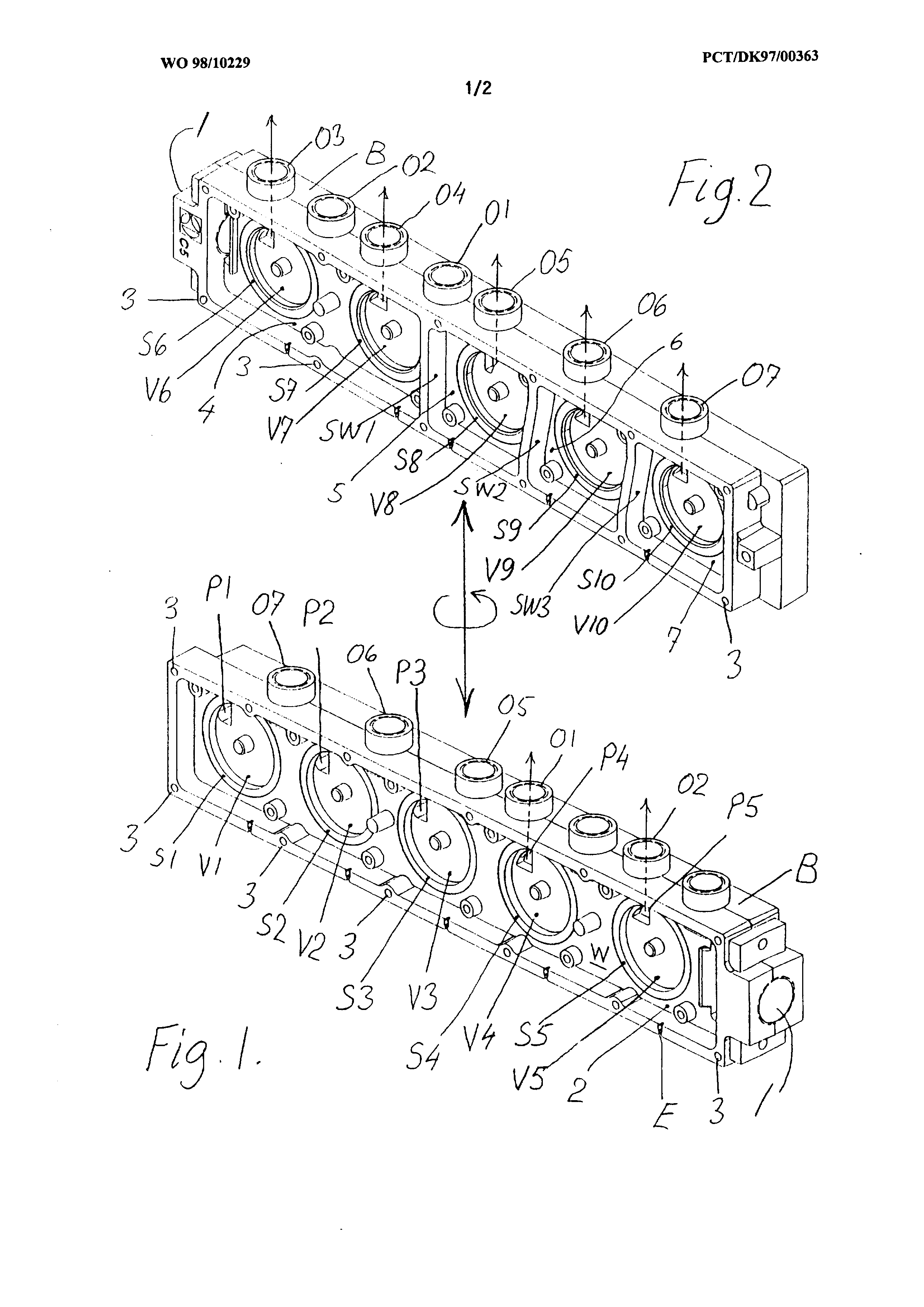
well as communication passages to outlets to individual gas burners . In an advantageous embodiment one side of the block constitutes a common ante-chamber connected to the gas supply, the valves on this side establishing connection to individual ante-chambers for valves on the other side. In a further advantageous embodiment the block consists of a suitably shaped three-dimensional body embodying all passages and connections, said body being closed on both sides by plate-shaped members which are fitted in a leak-tight fashion to said body. In a further advantageous embodiment, passages for wires supplying electrical control signals to the valves are sealed by the plate-shaped members against the outer edges of the ante-chambers . The invention will be further described with reference to the drawings, in which Fig. 1 shows a valve block according to an embodiment of the invention from one side, Fig. 2 shows the same valve block when turned 180° about a vertical axis, and Fig. 3 shows bottom and side views of the same valve block. In Fig. l is shown a gas inlet l which is placed at one short side in the valve block B. The valve block B may be machined or cast as a single unit and has essentially two sides and a dividing wall W. The gas inlet 1 communicates with a manifold space 2 on one side of the valve block which in use is covered by a tightly sealed lid which is not shown. The lid is fastened by means of fasteners which engage the holes 3 in the valve block. In the figure are shown five well-shaped depressions VI-V5 surrounded by circular smooth flat surfaces S1-S5 which each constitute the seat of a sealing member for a disc valve which is not shown. The discs are actuated, either directly, as in the case of a
piezoelectric type valve, or from valve stems which are slidably mounted in the lid and actuated, e.g. by means of a solenoid. When a disc is closed, no gas will pass into the interior of the valve in question. The wells VI, V2 , and V3 inside the valve each have a passageway P1-P3 through the dividing wall to the other side of the valve block, and by opening and closing the valves, the gas flow to the other side of the wall W may be controlled. Disposed somewhat differently, the wells W4 and W5 communicate via P4 and P5 with outlets 01, 02 on top of the valve block. Referring now to Fig. 2, it is seen that the' other side of the valve block is divided into four ante- chambers 4, 5, 6, 7 which each form closed spaces when a second lid is tightly sealed onto this side. Ante-chamber 4 is supplied from inlet 1 and is in reality also a manifold space, supplying outlets 03 and 04 via P6 and P7, respectively. This is also brought out in Fig. 3, in which in particular Fig. 3b shows that the gas from inlet 1 is divided into the two manifold spaces. The passageways enter the ante- chambers on the outside of valve elements V6-V10, S6-S10 similar to those on the other side of the valve block B. The outlets are connected to gas burners . It will be seen that the valves VI, V2 , and V3 have to be open in order that gas is supplied to the individual ante-chambers relating to valves V8 , V9 , and V10 on the other side of the wall W, and that no gas is supplied to the outlets 05, 06, or 07, unless the particular valves V8 , V9 , and V10 are open simultaneously. This construction is in effect a very compact series-connection of valves which enhances safety. Fig. 3 is divided into part figures 3a, 3b, and 3c in such a way that the valve block is seen from below in Fig. 3b and turned through 90°, with the outlet parts which are farthest from the plane of the drawing turned
upwards on Fig. 3a, and these parts turned downwards on Fig. 3c. In this way it becomes clear how the internal passages P in the valve block create the necessary communication between the ante- chambers , the valves V, and the outlets 0. It will be readily understood that the placement of the sidewalls SW1, Sw2 , Sw3 , and possible similar walls in locations not shown gives a further freedom in the distribution controlled by the valve block. It would be quite feasible to double the supply of gas by connecting valves or outlets in parallel, e.g. connecting 03 and 04 to the same gas burner . In case the valves are piezoelectric disc valves, the entire operation may occur between the cover and the valve body B. The electrical supply to a valve is by means of an insulated wire which has to pass through e.g. a wall, and in Fig. 1, E shows a passageway for such an electrical wire designed to operate the valve V5. The passageway is preferably made as a gas-tight passage which becomes leakproof when the lid is sealed on the side of the valve body. Similar passageways are distributed, one per valve, on both sides of the valve body.
A multi-valve structure (B) is used for distributing gas to
various burners. The valves are individually adjustable by electrical means, and they are placed in a structure in which the gas flow between two sides of a compartmentalised structure (SW1-SW3) is
controlled. The valve structure is used as a manifold at the same time, the gas exits (01-07) being in the plane of the dividing wall (W) between the two sides, but each communicating with one side
and one compartment only. The gas supply (1) occurs at the end of the structure and may occur to both sides simultaneously. A very compact construction is obtained which may minimise the length of gas
tube between the distribution structure and the burners. P A T E N T C L A I M S l. A multiple valve construction for gas valves employing a valve member with essentially translational movement fitted between an ante-chamber and an outlet, c h a r a c t e r i z e d i n that it is a single block (B) constituted of in particular circular valves (V1-V10) in a row on either side of a wall, with the centres of the valves on one side displaced approximately one half -diameter with respect to the other side, and with communication passages (P1-P3) between valve chambers on opposite sides of the wall as well as communication passages (P4-P10) to outlets (01- 07) to individual gas burners. 2. A multiple gas valve according to claim 1, c h a r a c t e r i z e d i n that the block consists of a suitably shaped three-dimensional body embodying all passages and connections, said body being closed on both sides by plate-shaped members which are fitted in a leak-tight fashion to said body. 3. A multiple gas valve according to claim 1 or 2 , c h a r a c t e r i z e d i n that one side of the block constitutes a common ante- chamber connected to the gas supply, the valves on this side establishing connection to individual ante- chambers for valves on the other side. 4. A multiple gas valve according to claim 1 or 2 , c h a r a c t e r i z e d i n that the outlets are disposed on at least one line which is near the outside edge of the dividing wall (W) and in the plane of the wall . 5. A multiple gas valve according to claim 1 or 2 , c h a r a c t e r i z e d i n that the inlet of gas occurs at an edge of the dividing wall (W) . 6. A multiple gas valve according to claim 5, c h a r a c t e r i z e d i n that the inlet supplies ante-chambers on both sides of the dividing wall.
7. A multiple gas valve according to any of the preceding claims, c h a r a c t e r i z e d i n that passages (E) for wires supplying electrical control signals to the valves are sealed by the plate-shaped members against the outer edges of the ante-chambers .