CROSS-CONNECTION BLOCK ADAPTER
CROSS-CONNECTION BLOCK ADAPTER BACKGROUND OF THE INVENTION The invention relates to a method described in the preamble of claim 1 for connecting a cross-connection block, a telecommunications apparatus and a subscriber connection. The invention also relates to an arrangement described in the preamble of claim 2 for connecting a cross-connection block, a telecommunications apparatus and a subscriber connection. The invention further relates to a telecommunications installation rack, cabinet or the like described in the preamble of claim 3, The invention also relates to a cross-connection block adapter described in the preamble of claim 4. Access node apparatuses are usually installed in telecommunications installation racks, cabinets or the like, and they are connected to the connection wires of the subscriber connections using a cross-connection field. The cross-connection blocks are divided into two parts, one part to which connection wires and surge arresters are connected and a second part to which the signal cables from telecommunications apparatuses are connected. The telecommunications apparatuses and cross-connections blocks are conventionally located in adjacent racks or cabinets. Installations also exist, in which the cross-connection blocks are located far away from the telecommunications apparatuses and the entire electronic equipment is located in a separate telecommunications room. The equipment is installed in such a manner that the connection wires to the subscriber connections are connected in advance to the cross- connection blocks to wait for the installation of the telecommunications apparatuses. When the telecommunications apparatuses and the signal cables have been installed and connected to the blocks, the signal cables are bridged from the subscriber connections to the addresses of the blocks of the apparatuses. Then, one subscriber connection corresponds to one address and the switching centre is able to connect the call correctly. The signal cable is usually connected to the telecommunications apparatus using a paired cable connection, in general a Euroconnector.
Sixteen subscriber addresses are usually connected to one 1/1 Euroconnector using a pair cable (UTP) twisted of sixteen pairs. The signal cable is usually connected to the cross-connection block with another connector. A great number of signal cables of this kind must be made for various equipment combinations and installation methods. Acquiring correct- sized signal cables requires training and professional skill. Signal cables and their installation constitute a significant expense item. Signal cables require installation space and hamper the cooling air circulation of electronics. BRIEF DESCRIPTION OF THE INVENTION It is thus an object of the invention to develop a solution for the above problems. The object of the invention is achieved by a method characterized in that a cross-connection block adapter is attached to second signal connectors of the telecommunications apparatus, the cross-connection block adapter comprising first connectors for connecting the cross-connection block adapter to second signal connectors of the telecommunications apparatus and second connectors for at least one connection wire to be connected between the cross-connection block adapter and the first signal connectors of the cross-connection blocks, and that at least one connection wire is connected between the first signal connections of the cross-connection block and the second connectors of the cross-connection block adapter. The arrangement of the invention is correspondingly characterized in that a cross-connection block adapter is attached to the second signal connectors of the telecommunications apparatus, the cross-connection block adapter comprising first connectors for connecting the cross-connection block adapter to the second signal connectors and second connectors for at least one connection wire to be connected between the cross-connection block adapter and the first signal connectors of the cross-connection blocks, and that at least one connection wire is connected between the first signal connections of the cross-connection block and the second connectors of the cross-connection block adapter. The method and arrangement of the invention provide the advantage that they do not require any special signal cables between the telecommunications apparatuses and the cross-connection blocks.
The solution of the invention also makes it possible to rearrange the telecommunications installation rack, cabinet or the like. The layout used in a telecommunications installation rack, cabinet or the like today is to place the telecommunications apparatuses on top of each other in the same rack and the cross-connection blocks in their own compartment. The reason for this solution comes from the classification of installers of telecommunications companies. The persons who work with cross-connection blocks are not allowed access to the telecommunications apparatuses. The present solution has the disadvantage that the extra heat generated by electronics installed in a rack warms up the racks installed on top. Increasing the circulation rate of the warmed-up air in a fan rack produces the same cooling effect as using cooler air at a lower circulation rate. The fan rack, however, increases the costs. The telecommunications installation rack, cabinet or the like of the invention is characterized in that a cross-connection block adapter is attached to the second signal connectors of the telecommunications apparatus, the cross-connection block adapter comprising first connectors for connecting the cross-connection block adapter to the second connectors of the telecommunications apparatus and second connectors for at least one connection wire to be connected between the cross-connection block adapter and the first signal connectors of the cross-connection blocks, that at least one connection wire is connected between the first signal connectors of the cross- connection block and the second connectors of the cross-connection block adapter, and that the installation rack of the cross-connection blocks is located immediately above or below the installation rack for telecommunications apparatuses. Cross-connection space above or below the installation rack for apparatuses provides a natural way of making more space for the rack installation. For instance, it simplifies cooling the apparatuses. Locating the cross-connection blocks below or above the telecommunications apparatus rack allows for shorter connection wires. The cross-connection block adapter of the invention is characterized in that the cross-connection block adapter comprises first connectors for connecting the cross-connection block adapter to the second signal connectors of the telecommunications apparatus and second
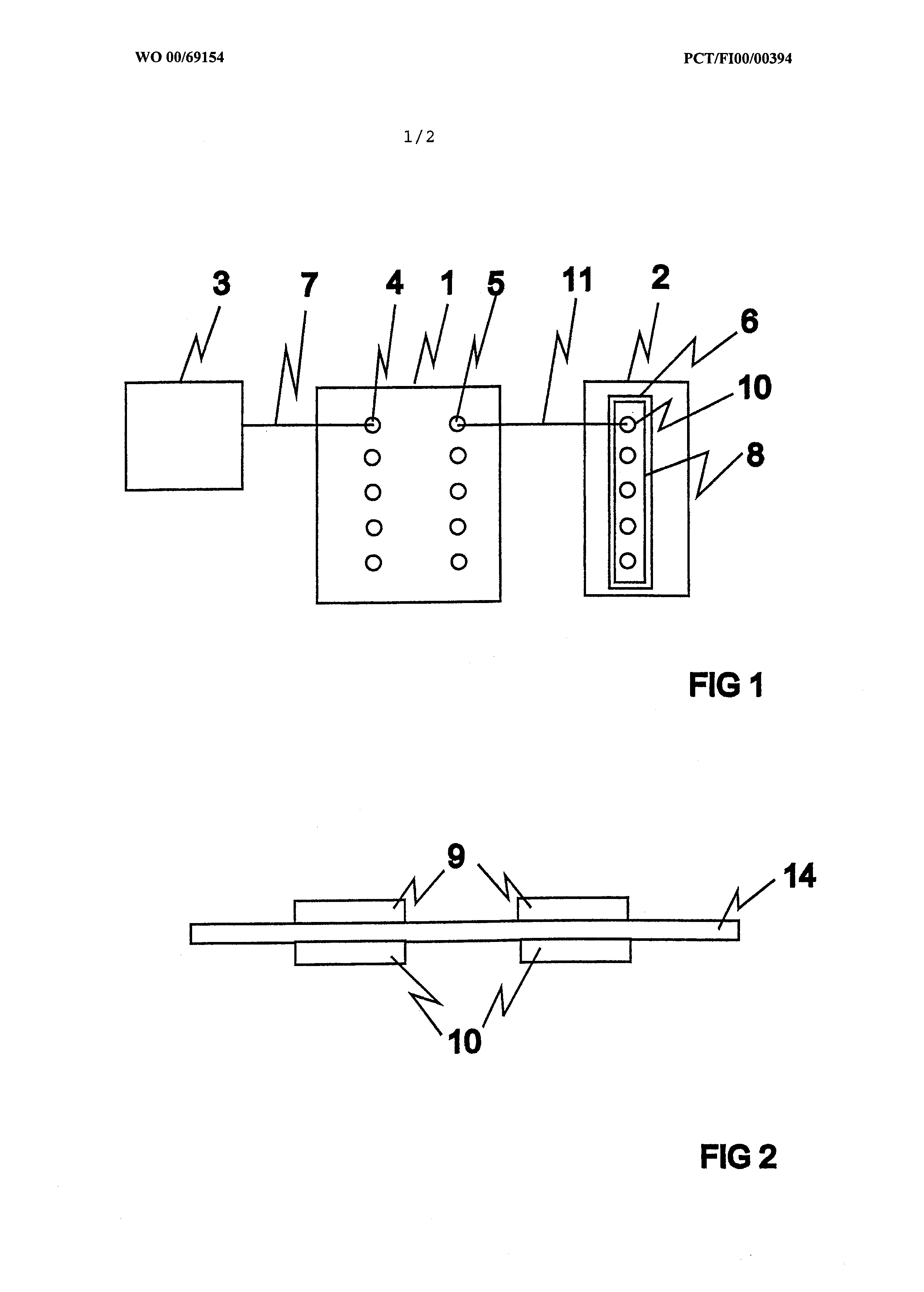
connectors for at least one connection wire connected between the cross- connection block adapter and the first signal connectors of the cross- connection blocks. Preferred embodiments of the cross-connection block adapter of the invention are set forth in the dependent claims 5 to 10. BRIEF DESCRIPTION OF THE FIGURES In the following, the invention will be described in greater detail by means of preferred embodiments and with reference to the attached drawings in which Figure 1 shows a schematic of the arrangement, . Figure 2 shows a cross-connection block adapter, and Figure 3 shows a telecommunications installation rack. DETAILED DESCRIPTION OF THE INVENTION Figure 1 shows a schematic of the arrangement for connecting a cross-connection block 1 , telecommunications apparatus 2 and subscriber connection 3. Because the cross-connection 1 , telecommunications apparatus 2 and subscriber connection 3 are items known per se, they are not described in greater detail herein. The cross-connection block 1 comprises connection wire connectors 4 and first signal connectors 5. For each subscriber connection 3, the cross-connection block 1 has one subscriber address pair made up of a connection wire connector 4 and a first signal connector 5. The number of subscriber address pairs in one cross-connection block 1 can be sixteen, for instance. The telecommunications apparatus 2 comprises second signal connectors 6. Sixteen subscriber addresses, for instance, may be connected to such a second signal connector 6. The telecommunications apparatus 2 is also connected to a switching centre (not shown). A connection wire 7 connected to the subscriber connection 3 is also connected to the connection wire connector 4 of the cross-connection block 1 , and the first signal connectors 5 of the cross-connection block 1 are connected to the second signal connectors 6 of the telecommunications apparatus.
A cross-connection block adapter 8 is attached to the second signal connectors 6 of the telecommunications apparatus 2, the adapter comprising first connectors 9 for connecting the cross-connection block adapter 8 to the second signal connectors 6 of the telecommunications apparatus 2 and second connectors 10 for at least one connection wire 11 to be connected between the cross-connection block adapter 8 and the first signal connectors 5 of the cross-connection blocks 1. The first connectors 9 and the second connectors 10 of the cross- connection block adapter 8 are connected to each other. At least one connection wire 11 is connected between the first signal connectors 5 of the cross-connection block 1 and the second connectors 10 of the cross-connections block adapter 8. The connection wire 11 is preferably a paired cable. The first signal connectors 5 and the second connectors 10 are preferably such that the connection wire 11 can be connected to the connectors without separate connection pieces. The invention also relates to a method for connecting a cross- connection block 1 , telecommunications apparatus 2 and subscriber connection 3. The cross-connection block 1 comprises connection wire connectors 4 and first signal connectors 5, and the telecommunications apparatus 2 comprises second signal connectors 6. In the method, the connection wire 7 of the subscriber connection 3 is connected to the connection wire connector 4 of the cross-connection block 1 , and the first signal connectors 5 of the cross-connection block 1 and the second signal connectors 6 of the telecommunications apparatus 2 are connected to each other. In the method, a cross-connection block adapter 8 is attached to the second signal connectors 6 of the telecommunications apparatus 2, the adapter comprising first connectors 9 for connecting the cross-connection block adapter 8 to the second signals connectors 6 of the telecommunications apparatus 2 and second connectors 10 for at least one connection wire 11 to be connected between the cross-connection block adapter 8 and the first signal connectors 5 of the cross-connection blocks 1. The first connectors 9 and the second connectors 10 of the cross-connection block adapter 8 are connected to each other. At least one connection wire 11 is connected
between the first signal connectors 5 of the cross-connection block 1 and the second connectors 10 of the cross-connections block adapter 8. The invention also relates to a telecommunications installation rack, cabinet or the like. The telecommunications installation rack has at least one installation rack 12 for cross-connection blocks 1 , with at least one cross- connection block 1 installed in it, and at least one installation rack 13 for telecommunications apparatuses, with at least one telecommunications apparatus 2 installed in it. The cross-connection block 1 comprises connection wire connectors 4 and first signal connectors 5. The telecommunications apparatus comprises second signal connectors 6. The connection wire 7 connected to the subscriber connection 3 is also connected to the connection wire connector 4 of the cross-connection block 1. The first signal connectors 5 of the cross-connection block 1 and the second signal connectors 6 of the telecommunications apparatus 2 are connected to each other. A cross-connection block adapter 8 is attached to the second signal connectors 6 of the telecommunications apparatus 2. The cross-connection block adapter 8 comprises first connectors 9 for connecting the cross- connection block adapter 8 to the second signal connectors 6 of the telecommunications apparatus 2. The cross-connection block adapter 8 also comprises second connectors 10 for at least one connection wire 11 to be connected between the cross-connection block adapter 8 and the first signal connectors 5 of the cross-connection blocks 1. The first connectors 9 and the second connectors 10 of the cross-connection block adapter 8 are connected to each other. At least one connection wire 11 is connected between the first signal connectors 5 of the cross-connection block 1 and the second connectors 10 of the cross-connections block adapter 8. The installation rack 12 for cross-connection blocks is located immediately above or below the installation rack 13 for telecommunications apparatuses. This shortens the connection wires 11 and simplifies the connections substantially. In the example shown in the figure, there are two installation racks 12 for cross-connection blocks above the installation rack 13 for telecommunications apparatuses.
The invention also relates to a cross-connection block adapter 8 to be connected to the telecommunications apparatus 2 which comprises second signal connectors 6 from which the signal can be forwarded to the first signal connectors 5 in the cross-connection blocks 1. Figure 2 shows a cross-connection block adapter 8. The cross-connection block adapter 8 comprises first connectors 9 for connecting the cross-connection block adapter 8 to the second signal connectors 6 of the telecommunications apparatus 2 and second connectors 10 for at least one connection wire 11 to be connected between the cross- connection block adapter 8 and the first signal connectors 5 of the cross- connection blocks 1. The first connectors 9 and the second connectors 10 of the cross- connection block adapter 8 are connected to each other. Figure 3 shows cross-connection block adapters 8 which are attached to the second signal connectors 6 on the front edge of the telecommunications apparatus. The cross-connection block adapter 8 of the invention can also be used in telecommunications apparatuses 2 in which the second signal connectors 6 are located in some other part of the apparatus 2, at the back of the apparatus 2, for instance. The cross-connection block adapter 8 shown in the figure also comprises a support structure 14. The cross-connection block adapter 8 is preferably detachably attached to the second signal connectors 6 of the telecommunications apparatus 2. This arrangement provides the advantage that the telecommunications apparatus 2 can, if necessary, be replaced with another telecommunications apparatus 2. Euroconnectors or D connectors are often used in telecommunications apparatuses 2. If the second signal connectors 6 of the telecommunications apparatus 2 are male connectors, the first connectors 9 of the cross-connection block adapter 8 are preferably female connectors, and correspondingly, if the second signal connectors 6 of the telecommunications apparatus 2 are female connectors, the first connectors 9 are preferably male connectors. The second connectors 10 of the cross-connection block adapter 8 are preferably such that they allow the connection of the connection wire 11
directly to the second connectors 10 without separate connection pieces. Such a solution simplifies installation and connection. The second connectors 10 of the cross-connection block adapter 8 can be IDC connectors, for instance. The cross-connection block adapter 8 preferably comprises locking elements (not shown) for locking the cross-connection block adapter 8 to the telecommunications apparatus 2 or to the installation rack 13 for telecommunications apparatuses. The purpose of the locking elements is to prevent installers with a lower classification from accessing the telecommunications apparatus. This makes it possible to install telecommunications apparatuses and cross-connection blocks in the same space in such a manner that the installation classification regulations are met. The locking elements can, for instance, lock the support structure 14 of the cross-connection block adapter 8 to the telecommunications apparatus 2 or to the installation rack 13 for telecommunications apparatuses. It is obvious to a person skilled in the art that while technology advances, the basic idea of the invention can be implemented in many different ways. The invention and its embodiments are thus not restricted to the examples described above, but can vary within the scope of the claims.
CLAIMS 1. A method for connecting a cross-connection block (1 ), a telecommunications apparatus (2) and a subscriber connection (3), the cross- connection block (1 ) comprising connection wire connectors (4) and first signal connectors (5), and the telecommunications apparatus (2) comprising second signal connectors (6), in which method a connection wire (7) connected to the subscriber connection (3) is connected to the connection wire connector (4) of the cross-connection block (1 ), and the first signal connectors (5) of the cross-connection block (1 ) and the second signal connectors (6) of the telecommunications apparatus (2) are connected together, c h a r a c t e r i z e d in that a cross-connection block adapter (8) is attached to the second signal connectors (6) of the telecommunications apparatus (2), the adapter comprising first connectors (9) for connecting the cross-connection block adapter (8) to the second signal connectors (6) of the telecommunications apparatus (2) and second connectors (10) for at least one connection wire (11 ) to be connected between the cross-connection block adapter (8) and the first signal connectors (5) of the cross-connection blocks (1 ), and in that at least one connection wire (1 1 ) is connected between the first signal connectors (5) of the cross-connection block (1 ) and the second connectors (10) of the cross-connection block adapter (8). 2. An arrangement for connecting a cross-connection block (1 ), a telecommunications apparatus (2) and a subscriber connection (3), the cross- connection block (1 ) comprising connection wire connectors (4) and first signal connectors (5), and the telecommunications apparatus (2) comprising second signal connectors (6), in which arrangement a connection wire (7) connected to the subscriber connection (3) is connected to the connection wire connector (4) of the cross-connection block (1 ), and
the first signal connectors (5) of the cross-connection block (1 ) and the second signal connectors (6) of the telecommunications apparatus (2) are connected to each other, c h a r a c t e r i z e d in that a cross-connection block adapter (8) is attached to the second signal connectors (6) of the telecommunications apparatus (2), the adapter comprising first connectors (9) for connecting the cross-connection block adapter (8) to the second signal connectors (6) of the telecommunications apparatus (2) and second connectors (10) for at least one connection wire 11 to be connected between the cross-connection block adapter (8) and the first signal connectors (5) of the cross-connection blocks (1 ), and in that at least one connection wire (11 ) is connected between the first signal connectors (5) of the cross-connection block (1 ) and the second connectors (10) of the cross-connection block adapter (8). 3. A telecommunications installation rack, cabinet or the like having at least one installation rack (12) for cross-connection blocks, with at least one cross-connection block (1 ) installed in it, and at least one installation rack (13) for telecommunications apparatuses, with at least one telecommunications apparatus (2) installed in it, the cross-connection block (1 ) comprising connection wire connectors (4) and first signal connectors (5) and the telecommunications apparatus (2) comprising second signal connectors (6), and the connection wire (7) connected to the subscriber connection (3) is connected to the connection wire connector (4) of the cross-connection block (1 ), and the first signal connectors (5) of the cross-connection block (1 ) and the second signal connectors (6) of the telecommunications apparatus (2) are connected to each other, c h a r a c t e r i z e d in that a cross-connection block adapter (8) is attached to the second signal connectors (6) of the telecommunications apparatus (2), the adapter comprising
first connectors (9) for connecting the cross-connection block adapter (8) to the second signal connectors (6) of the telecommunications apparatus (2) and second connectors (10) for at least one connection wire (11) to be connected between the cross-connection block adapter (8) and the first signal connectors (5) of the cross-connection blocks (1), in that at least one connection wire (11) is connected between the first signal connectors (5) of the cross-connection block (1) and the second connectors (10) of the cross-connection block adapter (8), and in that the installation rack (12) for cross-connection blocks is located immediately above or below the installation rack (13) for telecommunications apparatuses. 4. A cross-connection block adapter (8) to be attached to a telecommunications apparatus (2) comprising second signal connectors (6) from which the signal can be forwarded to the first signal connectors (5) in the cross-connection blocks (1), characterized in that the cross-connection block adapter (8) comprises first connectors (9) for connecting the cross-connection block adapter (8) to the second signal connectors (6) of the telecommunications apparatus (2) and second connectors (10) for at least one connection wire (11 ) to be connected between the cross-connection block adapter (8) and the first signal connectors (5) of the cross-connection blocks (1). 5. A cross-connection block adapter as claimed in claim 4, characterized in that it is detachably attachable to the second signal connectors (6) of the telecommunications apparatus (2). 6. . A cross-connection block adapter as claimed in claim 4, characterized in that the first connectors (9) are female or male Euroconnectors. 7. A cross-connection block adapter as claimed in claim 4, characterized in that the second connectors (10) allow the connection of the connection wire (11) directly to the second connectors (10) without extra connection pieces. 8. A cross-connection block adapter as claimed in claim 4, characterized in that the second connectors (10) are IDC connectors.
9. A cross-connection block adapter as claimed in claim 4, characterized in that the cross-connection block adapter (8) comprises a support structure (14). 10. A cross-connection block adapter as claimed in claim 4, characterized in that the cross-connection block adapter (8) comprises locking elements for locking the cross-connection block adapter (8) to the telecommunications apparatus (2) or to the installation rack (13) for telecommunications apparatuses.