Vorrichtung und verfahren zum abrollen von draht
The invention refers to an unwinding device for intermittent kurT_.zeitigen unreeling from wire from a wire coil and a procedure for unreeling from wire from a wire coil to a bundle binder, by taking the bundle binder the wire intermittently from of that off wire coil I eats.
Background of the invention and well-known state of the art bundle binder, as they are descriptive for example in SE-C2-509 532, work intermittently and take wire off, in order to bind it around a Baleen, e.g. a paper fiber bundle.
After a first processing step of the Herumbindens the bundle is induced usually for a recent processing step of the Herumbindens parallel and in the distance to first. The cycle time of the bundle binder can be less than 5 seconds and k6nnte still more reduce, if the wire speed and wire acceleration are increased kSnnten, but then increases the risk of a confusion and a knot formation with the wire at the unwinding device.
The acceleration and speed of wire m0ssen from there against the risk of a procedure interruption to be weighed out.
The JP 11,060,069 reveals a device for the avoidance of vibrations w it-ends to the delivery of a wire. This device consists of two roles, which are against each other relocatable arranged on FLihrungsstangen and 5ber a feather/spring cooperate. The wire which can be delivered is wound on these roles into a loop. By this arrangement are Unregelm il%igkeiten in the course of motion w it-end to the wire delivery to become balanced. However that is beschr inkt m6glich, since it to of that caused feather/spring, unerw0nschten oscillations in this way only comes, whose R0ckkopplung can come on the more or less strained wire with the further processing to substantial problems.
In addition z ihlen st indige nderungen in the wire tension, unregelm l ige delivery of the wire and by mechanical oscillations caused Besch ldigungen from machines, roles, coils and such.
Article and ku e description of the invention the invention sits down the goal the problems resulting in from the state of the art 15sen and a hShere wire acceleration and wire speed with intermittent unreeling from wire from a wire coil m6glich to make itself.
Invention in accordance with IR this goal with an initially erw&hnten unwinding device is achieved by it that it covers an acceleration compensating element einschliel lich a Rades, Liber of which the unreeled wire forwards and zurL ck in a loop I iuft, which wheel is mobile essentially toward the loop, over with movement in a direction the Schlingenl nge to make smaller and in the other direction the Schlingenl Inge to vergr6 ern, and that the wheel is burdening in the direction, and that a D is connected mpfelement with the wheel to the D inoculation of its acceleration.
An acceleration reconciliation in form of a Rades is assigned to the unwinding device to make Jber smaller of which the unreeled wire in a loop vorund zurSckl iuft, whereby the wheel is mobile essentially toward the loop, by with movement in a direction the SchlingenI Inge and with movement in the other direction the Schlingenl Inge to vergrSi3ern, and this wheel is in the direction loaded.
A special goal of the invention is it, with unreeling the wire to a bundle binder to erm6glichen that the bundle binder takes the wire with a hbheren acceleration and top speed from the unwinding device off.
Invention in accordance with IL this goal with one is achieved initially erw ihnten procedures by the fact that the wire is arranged to run in a loop which is burdening against increasing Schlingen3 RK 414,123 B Impinge and is mpfelement connected with a D, and that the load is adapted to the duty cycle of the bundle binder, so that the Schlingenl nge decreases, if the bundle binder wire takes off, and its Gr613e lt beibeh to take off to the bundle binders aufh6rt, wire.
The D mpfelement works as brake and ensures dafLir that the accelerated wheel is braked. Oscillations kSnnen thereby efficiently abged inoculate become. Preferential AusfLihrungen of the invention is in the Unteranspr chen defined.
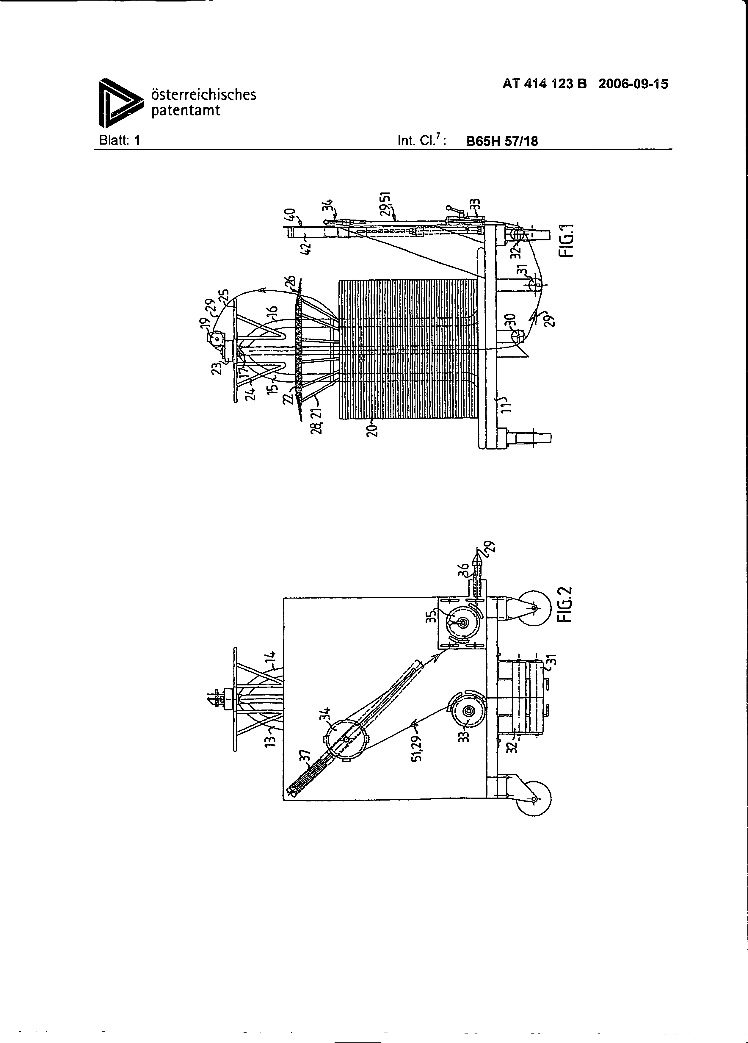
Furze description of the designs Fig. 1 is represented a side view of an unwinding device, as a Ausf0hrungsform of the invention.
Fig. 2 is a side view in a right angle to in Fig. 1 side view shown.
Fig. a detail shown in the preceding figures shows 3 in grSBerem MaBstab.
Fig. 4 is a side view, like by the arrows 4-4 in Fig. 3 indicated.
Fig. 5 shows in gr6Berem MaBstab and on average a part of the Fig. 1.
Fig. 6 is a cut along the line 6-6 in Fig.
Fig. 7 is a cut along the line 7-7 in Fig. 6.
Detailed description of the represented Ausfghrungsform the unwinding device shown in the figures covers one consisting on decaying abgestiJtzten steel framework 11 with upright wire coils a Stander, of four pipes 13-16, whose upper ends are geschweiBt einw irts curved and to a HiJlse 17. A coil 20 with wire, gew6hnlich steel wire, is wound on the wire Spulenst Indian 13-16, and a conical tubular structure 21 with a plastic ring 22 rests on the upper section of the wire coil 20. The HLilse 17 tract a turning ring 23 and a tubular structure 24 with a ring 25. The turning ring has an eccentrically arranged Ff3hrungsrad 19, whose horizontal axle extends perpendicularly to the vertical axle of the H01se 17. The tubular structure 21 is conical, has however a straight section 27 with a somewhat smaller diameter than the inside diameter of the wire coil 20. The tubular structure 21 is inserted into the wire coil 20, so that you are gefehrt straight lines section 27 by the wire coil and the conical section 28 more ber the straight section on the wire coil rest. The tubular structure 21 is fixed to RTS thereby in the wire coil, can follow however the upper section of the wire coil abw, if the wire coil w hrend the revolution procedure k (3rzer becomes. The tubular structure 21 is prevented from the rotation by the pipes 13-16, which are arranged between four einw irts curved Sti.itzen 38.
The plastic ring 22 is vergr6l ert in the Fig. 3 and 4 shown. It has cast in Dr ihte, which radially at its extent as an edge of bristle 26 rises up after auBen. The Dr hte is from one verschleiBbest ndigen and flexible material, zweckm Big a plastic such as nylon, and their diameter solute 1 mm eberschreiten and can for example 1-2 mm be. Their before-rising up Linger can be zweckm IL industrial union between 7 and 10 cm, and they kSnnen in a row as represented or in several rows to be arranged. The plastic ring 22 is screwed on the tubular structure 21, and the bristle ring 26 will always have the same position regarding the upper end of the wire coil, if the upper end of the wire coil w lowers itself hrend the revolution procedure, since the tubular structure 21 rests on the wire coil, whereby their conical section 28 is arranged above the straight FLihrungsabschnittes 27. This organization prevents that the wire w it-end the revolution procedure one gets jammed.
The wire 29 of the coil is led in a sheet aufw RTS to the FLihrungsrad 19 of the turning ring 23 and abw irts by the HSlse 17 and thus abw RTS by the wire coil to a Fehrungswalze 30 and 13ber two or several F (Jhrungswalzen of 31 and 32 and aufw irts 0ber two F far to a Fi3hrungsrad 33 and hrungsr or 34 and 35 to a Ausgabefi] hrung 36. The Fehrungsr of the 33 and 35 is installed on a vertical plate 40, which is attached at that 4 RKs 414,123 B steel framework 11, and which is F hrungsrad 34 fastened to a carriage 41, which slides in a FLihrung 42, which is fastened to the plate 40.
Fig. 5 a L is ingsschnitt by the F0hrung 42. As clearest from the Fig. 5-7, has the Fehrung 42 the form of a slit pipe comes out. The F0hrungsrad 34 is fastened to a tap 43, which is fixed in the carriage 41 and rises up by the slot 44 the F0hrung 42 after aul EN. The carriage is fastened to a tension spring 45, which seeks to pull the carriage upward into the final position, in which it in all figures is shown, so that the F0hrungsr or 33, 34, 35 to a balance loop 51 deform the wire with one another. An air cylinder 46 RST is fastened to a fork 47, which is attached at the framework, and which is plate 40 likewise fastened to the fork 47. The piston rod 48 of the air cylinder 46 is fastened to the carriage 41, and the air cylinder has two throttled Einbzw. Ausl isse 4g, 50 directly into the Atmosphere the m0nden. The entire unwinding device is, as evidently, very compactly, and all details are carried by the framework 11 abgestQtzten on Riders, so that the unwinding device can be moved easily as a unit. If a wire coil is emptied, the whole unwinding device can be exchanged easily against an unwinding device with full wire coil. Since the wire end from the Ausgabefehrung 36 stands out, the exchange can be hrt very rapidly ausgefL.
In the resting position, if no wire is taken off from of that Ausgabef hrung 36, the carriage 41 and from there the F0hrungsrad 34 in the position shown in the figures are, and the wire loop 51 between decaying 33 and 35 and more eber the wheel 34 has its maximum lung. If the wire consumer begins plStzlich to take wire from of that off AusgabefLihrung 36 the wire tension draws the F {to Jhrungsrad 34 and the carriages 41 to the flat steel bars hrungsr idern 33 and 35, so that the wire loop becomes at the same time smaller 51 and begins an unreeling from the wire role. The spring action of that tension spring 45 is at first small, and at the same time the air cylinder has 46 at the beginning of no braking action, since Atmosph Irish printing in both chambers of the cylinder prevails. The brake effect of the cylinder h ingt of the Dr0cken in both cylinder chambers off, and this Dr0cke h ngen for their part from the speed of the piston rod and the zur0ckgelegten way off, there Einbzw. Ausl isse 49, 50 constant throttles form.
The brake effect of the cylinder increases from there at the same time if the braking force of the feather/spring increases, if the F accelerates itself and causes {Jhrungsrad 34 to the F0hrungsr&dern 33 and 35 that the balance loop 51 becomes smaller. If the wire then plStzlich aufh6rt from the AusgabefLihrung 36 to be taken off the cylinder 46 at first with the feather/spring 45 cooperates, in order the FLihrungsrad 34 zurLickzuziehen, and begins to brake thereupon the movement of the FiJhrungsrades 34 at the same time, if the spring action decreases.
A bundle binder causes a high acceleration of the wire at the AusgabefiJhrung 36, but the controlled movement of the FLihrungsrades 34 causes that wire acceleration at the wire coil is many smaller, since the balance loop 51 w becomes smaller hrend acceleration. If the bundle binder terminates then pl6tzlich the wire departure, the kinetic energy brings with itself that the departure does not aufhSrt equal pl6tzlich, but the Drahtl&nge, which is caused by the difference in the slowing down, is taken up by VergrSI3erung of the balance loop, which reduces the risk of confusion and knots.
The invention makes from there better course nglichkeit and a wire departure speed for erh6hte mSglich. The wire departure speed knows 4.5 m/s 0berschreiten without the risk of process interruptions, even if the entire connection cycle takes less than 5 seconds. If the bundle binder takes the wire off with an acceleration, which a constantly high speed of w it-end to the final phase of the wire departure reached, the FLihrungsrad before the end may not walk the departure so far aufw irts that the loop is 52 like that grol3 that it cannot take up the entire 0bersch0ssigen wire after the end of the departure.
It is necessary to adjust the feather/spring 45 and the brake cylinder 46 to the characteristics of the bundle binder so that the FLihrungsrad 34 and thus on the balance loop 51 affecting Kraft to the duty cycle of the wire consumer (bundle binder) is adapted.
RK 414,123 B RST if the bundle binder the wire 29 of the AusgabefLihrung 36 the unwinding device 0ber the FOhrungsr or 33-35 takes off, follows the F (Jhrungsrad 19 of the turning ring 23 the departure of the wire after, and the wire 29 slides along 26 and at the steel ring 25 at the bristle ring.
The bristle ring 26 of the unwinding device reduces the risk of the formation of confusion and knots likewise, since it brakes the wire continuously. At the same time, where the bristle ring forms a brake with sufficient braking action with plStzlichen stops, it does not cause ung nstige braking action on the start. A too strong braking action when starting kSnnte a wire break causes. The bristle ring 36 increases those course inglichkeit (usefulness) from there still more.
Patentanspr£ che:
Unwinding device for intermittent brief unreeling from wire (29) of a wire coil (20), to make Liber smaller of which the unreeled wire forwards and zur0ck in a loop (51) I iuft, which wheel is mobile essentially toward the loop, over with movement in a direction the Schlingenl nge thereby characterized that it covers an acceleration compensating element (33-35, 41-59) einschliel lich a Rades (34), and in the other direction the Schlingenl nge too vergrSl ern, and that the wheel is burdening in the direction, and that a D&mpfelement (46, 48) is connected with the wheel to the D&mpfung of its acceleration.
2. Unwinding device according to requirement 1, by the fact characterized that the wheel (34) is burdening by a feather/spring (45).
3. Unwinding device according to requirement 2, by the fact characterized that the D&mpfelement consists a throttle (49, 50) of an air cylinder (46, 48) in connection with Atmosphere more eber.
4. Unwinding device according to requirement 3, by it characterized that the air cylinder (46, 48) is working doubly, and that its two cylinder chambers 5ber throttles (49, 50) in connection with the Atmosphere it is.
Unwinding device after one the preceding Anspr che, by it characterized that she is intended a framework (11) with a Stander (13-16) flat steel bars r the wire coil (20), a turning ring (23), coaxially with the Drahtst&nder and fur the admission of the unreeled wire and the wire by the turning ring and Stander fLihrt, and FQhrungselemente (30, 32) enclosure, those the wire yon the center of the Standers to the acceleration balance element (33-35, 41-50) it fLihren, which is appropriate at the framework (11) laterally the Drahtst of Indian.
Unwinding device according to requirement 3, by the fact characterized that it covers a ring also after aul EN arranged bristles (26), which is coaxially arranged with the wire coil on the Drahtst more nder (13-16) between the wire coil (20) and the turning ring (23) and, so that the wire (29) is pulled with the revolution procedure along the bristles.
o procedure for unreeling from wire from a wire coil to a bundle binder, by taking the bundle binder the wire intermittently from the wire coil from I off eats, by the fact characterized that the wire is arranged to run in a loop which is burdening against increasing Schlingenl Inge and is connected with a D inoculation element, and that the load is adapted to the duty cycle of the bundle binder, so that the Schlingenl nge decreases, if the bundle binder wire takes off, and its Gr61 e ilt beibeh to take off to the bundle binders aufh6rt, wire.
8. Procedure according to requirement 7, by the fact characterized that the wire yon the wire coil A wire consumer, such as a bale binder, draws wire from a wire coil on an unreeling device. The entire unreeling device is mounted on a wheel-supported frame, and it comprises a wire loop and an acceleration balancer which is effective when the wire consumer starts to draw wire out from the unreeling device. The wire loop comprises a wheel, which is loaded by a spring, and an air cylinder, which is coupled to the wheel for damping the acceleration of the wheel. RST if the bundle binder the wire 29 of the AusgabefLihrung 36 the unwinding device 0ber the FOhrungsr or 33-35 takes off, follows the F (Jhrungsrad 19 of the turning ring 23 the departure of the wire after, and the wire 29 slides along 26 and at the steel ring 25 at the bristle ring.
The bristle ring 26 of the unwinding device reduces the risk of the formation of confusion and knots likewise, since it brakes the wire continuously. At the same time, where the bristle ring forms a brake with sufficient braking action with plStzlichen stops, it does not cause ung nstige braking action on the start. A too strong braking action when starting kSnnte a wire break causes. The bristle ring 36 increases those course inglichkeit (usefulness) from there still more.
Patentanspr£ che:
Unwinding device for intermittent brief unreeling from wire (29) of a wire coil (20), to make Liber smaller of which the unreeled wire forwards and zur0ck in a loop (51) I iuft, which wheel is mobile essentially toward the loop, over with movement in a direction the Schlingenl nge thereby characterized that it covers an acceleration compensating element (33-35, 41-59) einschliel lich a Rades (34), and in the other direction the Schlingenl nge too vergrSl ern, and that the wheel is burdening in the direction, and that a D& mpfelement (46, 48) with the wheel to the D& mpfung is connected for his acceleration. 2. Unwinding device according to requirement 1, by the fact characterized that the wheel (34) is burdening by a feather/spring (45). 3. Unwinding device according to requirement 2, by the fact characterized that the D& mpfelement from an air cylinder (46, 48) in connection with Atmosphere more eber a throttle (49, 50) exists. 4. Unwinding device according to requirement 3, by it characterized that the air cylinder (46, 48) is working doubly, and that its two cylinder chambers 5ber throttles (49, 50) in connection with the Atmosphere it is.
Unwinding device after one the preceding Anspr che, by the fact characterized that it a framework (11) with a Stander (13-16) flat steel bars r the wire coil (20), a turning ring (23), that coaxially with the Drahtst& more nder and fur the admission of the unreeled wire intended is fLihrt and the wire by the turning ring and Stander, and FQhrungselemente (30, 32) enclosure, those the wire yon the center of the Standers to the acceleration balance element (33-35, 41-50) fLihren, which is appropriate at the framework (11) laterally the Drahtst of Indian.
Unwinding device according to requirement 3, by the fact characterized that it covers a ring also after aul EN arranged bristles (26), which is coaxially arranged with the wire coil on the Drahtst more nder (13-16) between the wire coil (20) and the turning ring (23) and, so that the wire (29) is pulled with the revolution procedure along the bristles.
Procedure for unreeling from wire from a wire coil to a bundle binder, by taking the bundle binder the wire intermittently from the wire coil from I off eats, by the fact characterized that the wire is arranged to run in a loop which is burdening against increasing Schlingenl Inge and is connected with a D inoculation element, and that the load is adapted to the duty cycle of the bundle binder, so that the Schlingenl nge decreases, if the bundle binder wire takes off, and its Gr61 e ilt beibeh to take off to the bundle binders aufh6rt, wire. 8. Procedure according to requirement 7, by the fact characterized that the wire yon the wire coil 6 RKs 414,123 B aufw& RTS is gefLihrt more eber a turning ring, abw irts by the wire coil and outside to the side of the wire coil to a device at the side of the wire coil for the formation of the loop.