PROCEDURES FOR MEDIATING INFORMATION PACKAGES AND SWITCHING PLANT FOR WOULD DRIVE OUT THE PROCEDURE.
The invention concerns a procedure after the generic term of the patent claim l and a switching plant after the generic term of the patent claim 4.
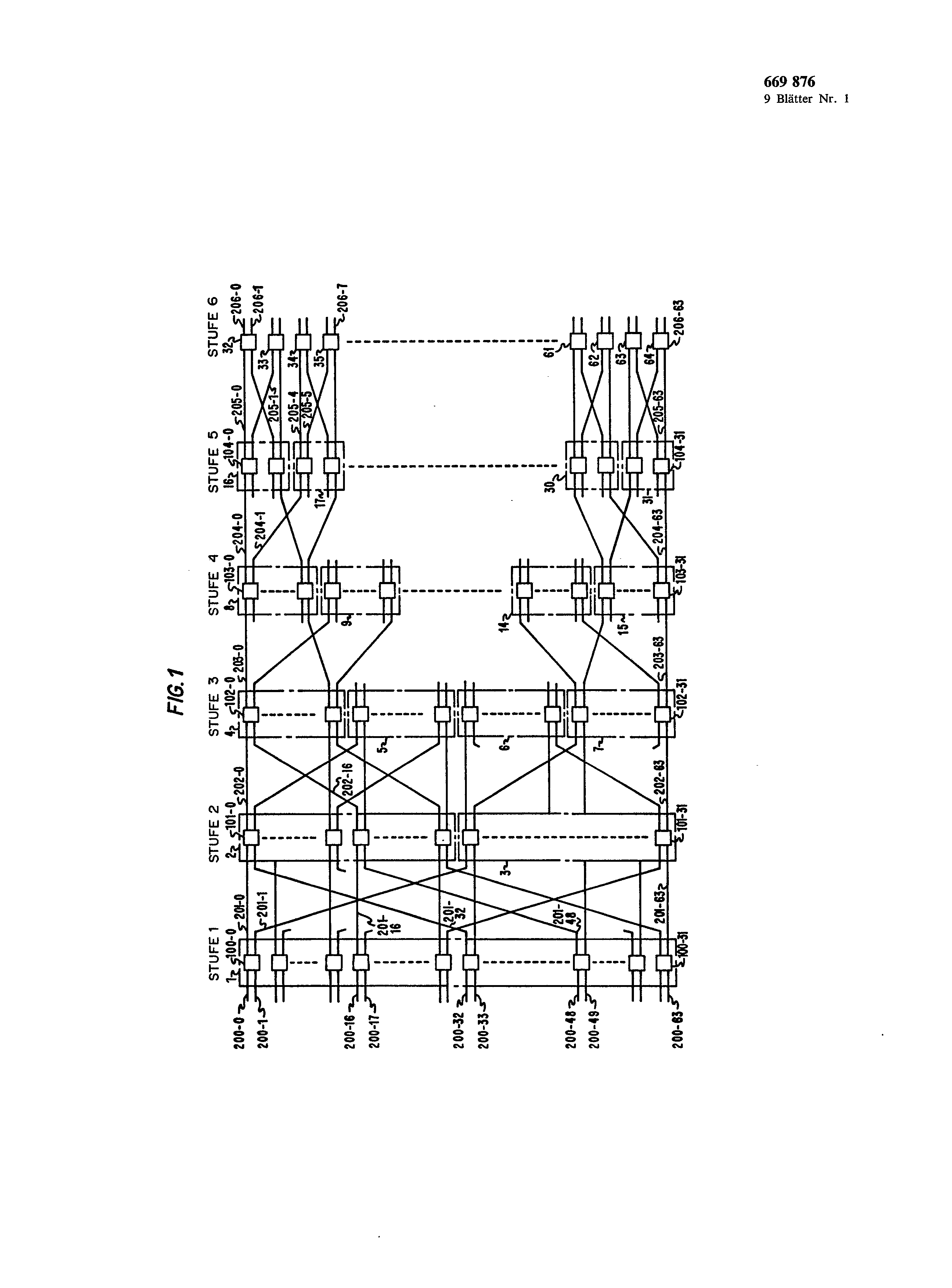
Routing-looking for InformationspaketvermittlungskoppelfeIder, for example such, which contain unbuffered, so-called BanianVermittlungsknoten, transfers packages over the switching network on the basis from address information, which is given before the transmission of the package over the switching network. Such a switching network possesses only in each case only one way between each entrance output's pair of the switching network and is in Fig. 1 represented. Since connecting a connection through contains the necessity contrary to the transmission of a package the fact that a way remains existing ffir an indefinite Zeitdaner cannot be transferred information so easily according to kind of communications over a well-known Banian switching network, since a large part of the ways was blocked. In addition such well-known switching networks are reduced by switching network minutes requirements to the transmission of packages. Although by means of a packet switching language and data will transfer smaller to middle range can, broadband data must be obtained, for example video information about communications. For the supply of the suggested new kinds of Datenund Fernsprechdiensten it is desired to have a switching plant available both Informationspaketals also a Vcrbindungsweg switching ermöglicht.
A further problem with the presence only one way are the effects of unbalanced traffic conditions in the switching network. The difficulties arising with it are the result of the structure of a fundamental Banian switching network. The structure in accordance with Fig. 1 consists of a multiplicity of stages. The first stage exhibits switching node 3,669,876 100-0 to 100-31. The second stage contains switching node 101-0 to 101-31. From Fig. 1 results that the first stage of the switching network under responding gives in the address addresses the package to a half of the switching network, i.e. the sections 2 and 3 of the second stage, and that then the package leads the second stage of the switching network to the sections 4 to 7 of the third stage. Fourth, fifth and sixth stage lead then the package under responding in its address addresses to the correct outlet line. Under intended unbalanced Verkahrsbedingungen lo the basic structure of the Banian switching network leads for concentrations of packages in certain knots of the third Stufe.
The following example describes the effects of unbalanced traffic conditions in the third stage. It is accepted that packages will transfer 200-0, 200-1, 200-16, 200-17, 200-32, 200-33.200-48 and 200-49 to the lines 206-0 to 206-7 from the lines. All packages of these input lines must be transferred over the knot 102-0 to the following ways. The transmission path of the lines 200-0 and 200-1 to the outlet lines 206! to 206-7 3. a way of the input lines 200-16 and 200 runs over the links 201-0 and 202-0 as well as the knot 102-0 of the stage! 7 to the outlet lines 206-1 and 206-7 runs over the links 201-16 and 202-16 and the knot 102-0. The way of the input lines 200-32 and 200-33 to the outlet lines 206-1 to 206-7 runs over the links 201-32 and 202-0 as well as the knot 102-0. Accordingly the way of the input lines leads 200-48 and 200-49 to the Ausgangsleítungen across the links 201-48 and 202-16 as well as the knot 102-0. The way the outlet lines mentioned by the knot 102-0 to runs over the links 203-0, 204-0 or 204-1 and 205-0 or 205-1 and 205-4 or 205-5. One recognizes that the traffic capacity of the switching network limits 102-0 with this example by the traffic capacity of the knot ist.
In addition, if the knot 102-0 fails, no possibility is present, communications between the input lines mentioned and the outlet lines mentioned herzustellen.
A well-known procedure for moderating Zuverlässigkeitsund of traffic problems in a away-steering switching network descriptive in a report “development OF A Voice Funnel system”, Bolt, Beranek and Newman Inc., report No. 4098, August! 979, sides III-29 to 111-76. There the use of an additional stage of Banian switching nodes at the entrance of a away-steering switching network is described for the solution of the problems mentioned above regarding unbalanced traffic conditions and regarding the reliability. The report mentioned suggests that this additional ouple stage is identical to the other stages of the switching network and is used under adding an additional address bit in the address field of each package, which is led across the switching network. This additional ouple stage became the first stage 1 in Fig. precede 1. The additional address bit was steered by hardware or software outside of the switching network and determines the way over the switching network. The hardware or software evaluates this bit, in order to go around a knot, failed or strong traffic unterliegt.
Mentioned the procedure suggested in the report made possible adding of more than a special way over the switching network, it remains however the difficulty that an additional stage must be added to the switching network and that the decision, which way is to be used pleases outside of the switching network becomes. Beyond that mentioned the switching network described in the report can only for mediating packages used werden.
The described difficulties become according to invention by in the characteristic part of the patent claims 1 and 4 stated characteristics gelöst.
In addition the process steps can plan the transmission of final signals by a distributed control at the end of the information of a switched connection about a manufactured way and dissolution of the way in everyone the switching node with the receipt of these Endsignalc. In order to guarantee that only one switching node of a sentence in a given stage responds to information of a given Paketoder of communications, a switching node transfers after admission of and a responding in the address way steering element address an entrance link occupation signal to the other switching nodes the responding knots of containing sentence. The other switching nodes step with receipt of the entrance link occupation signal concerning this way into the free line condition ein.
A technical progress can be achieved with a structure of switching network, which makes simultaneous Informationspaketund for connecting by attitude possible, by the fact that several ways are already-placed over a away-steering switching network between two arbitrary, given Eingangsund Ausgangsanschlfissen, without further switching nodes are as necessary with well-known away-steering ouple feathers/springs or external tax procedures must be used. The effects of uneven traffic conditions and disturbed switching node in the switching network are reduced, there several ways present sind.
With advantage the switching network exhibits a multiplicity of stages, which possess ever connected switching nodes. Each switching node of a stage is connected with switching nodes in the next stage. A given sentence of switching nodes of a stage is connected with a certain sentence of switching nodes in the preceding stage by links, and each switching node of this sentence can manufacture a way to the next stage under responding to address information, which was transferred from a preceding switching node over any link. Since more than one switching node of a given stage with address information from a preceding stage can respond to the production of a way, a multiplicity of ways is over the switching network vorhanden.
In favourable way a way is opened with the receipt of a sentence of end identifier signals, those contained in the package data or the information for connected through connections sind.
Further each switching node under Anso designates speaks on the arrival of address signals one the switching node of the sentence in the next stage, which is to take up the address information furthermore and each switching node goes under responding on a message non--available signal from the characterized knot of the set of the next stage into a free line condition. Beyond that the switching node transmits a message non--available signal under responding to the message non--available signal to the preceding Stufe.
If in addition the switching node does not receive a message non--available signal from the next stage back, it gives a Eingangszwisehenleitungs occupy signal to the Vermittlnngsknoten of its sentence, in order to indicate the other switching nodes of the sentence that this special link is in active use and that the other Vermittlnngsknoten is not to address connecting information on any Paketoder, those over this special link transferred wird.
a sentence of switching nodes exists 669,876 4 with advantage in a certain stage to a pair of switching nodes, which are combined into a pair in the following way:
each knot of the pair is represented by a binary number, which defines its position within the stage. If the position of a knot of the pair is given, the other knot of the pair is defined by the fact that complements the bit locations of the binary number for the given knot position werden.
In detail the position of the other knot is defined, as the bit location of the given number, which is more fennummer equal the Stul0, is complemented, if the level number is smaller or equal to the half total number of stages in the switching network and as the niedrigststellige bit location of the given number is complemented, if the level number is larger than the half total number of stages. Another, special kind for the definition of the position of the pair of switching nodes is the following: if the position of a first knot of the pair is given, then the second knot of the pair is defined, as the bit location of the binary number of áes second knot is complemented, which is equal to the half total number of stages less the level number plus I, if the level number is smaller or equal to the half total number from stages and as the lowdigit bit location is komplemenfiert, if the level number more largely than the half total number of stages ist.
The invention becomes following on the basis a remark example in connection with the designs beschrieben.
In the designs show:
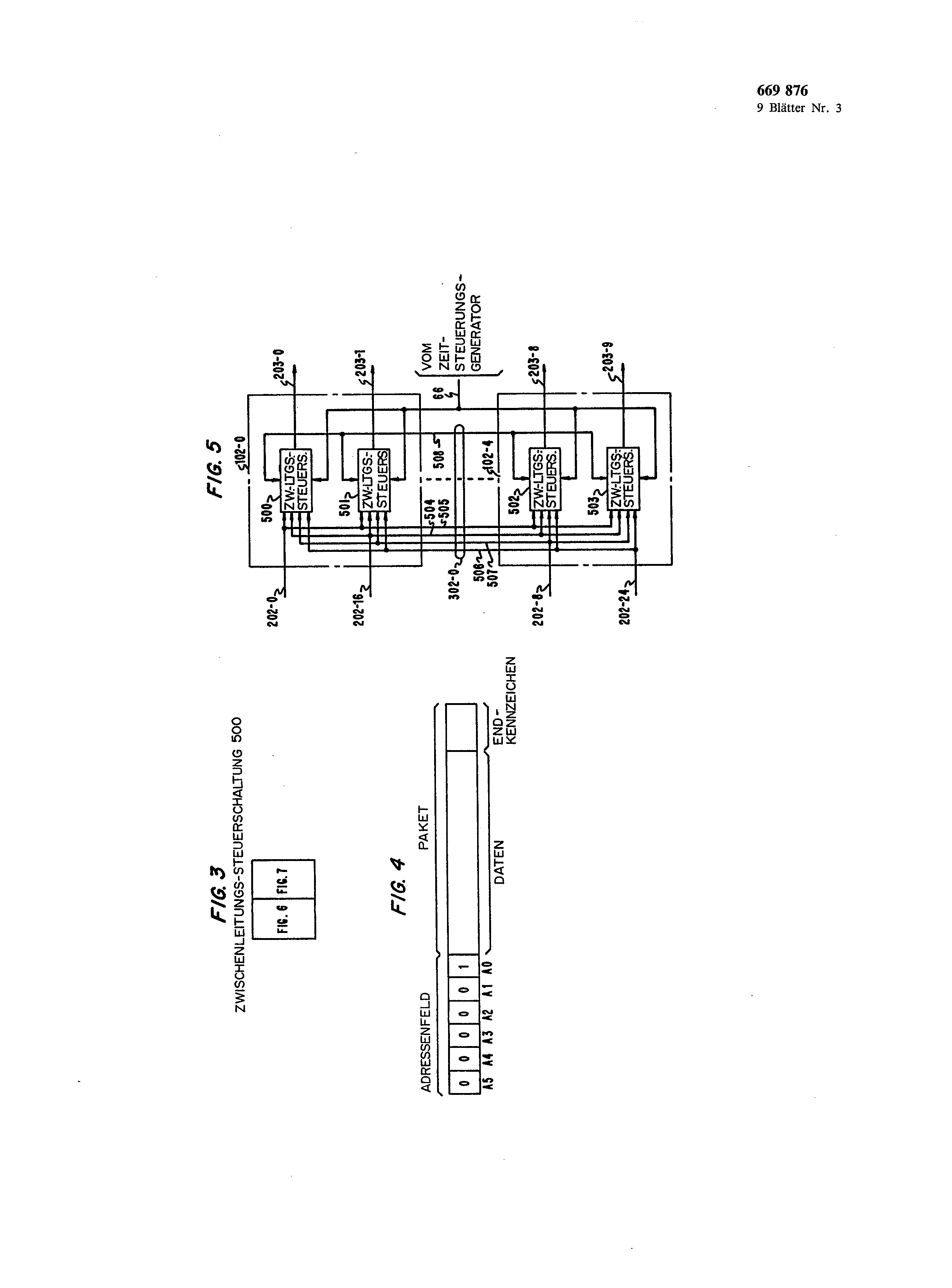
Fig. 1 as Bloekschaltbild a Leitwegsuehendes information packet-switched network work after the state of the art; Fig. 2 the Bloeksehaltbild an information packet-switched network work after the invention; Fig. 3 the Zusammengehörigkeit of the Fig. 6 and 7; Fig. 4 information, the one feeder line controller during the composition and way steering element of an information package about the telephone exchange network work after Fig. 2 sends; Fig. 5 more exact Bloeksehaltbild of the switching node 102-0 in Fig. 2; Fig. 6 and 7 more exact details of the Zwisehenleitungssteuerung 500 of the switching node 102-0; Fig. 8 a Zeitdiagramm for the signals, those with the production of a way over the telephone exchange network work after Fig. 2 use finds; Fig. 9 the temperature-concentration diagram, that the controller 621 in Fig. follows 6 during the transmission of information over the switching nodes 102-0; Fig. 10 as Bloeksehaltbild the feeder line Stenergerät 207-0 in Fig. 2; Fig. 11 as block stop picture a re-organization of the telephone exchange network work after Fig. 2.
Fig. a remark example of an information packet-switched network work shows 2 or - switching network, the subject of the invention is. The connections within a Absehnittes of a certain stage, for example the Absehnitts 3 of the stage 3, are exemplary for all connections within all sections of the respective stage. The way of the connections between two knots of a pair is more exactly represented for the knots 104-0 and 104-1. For the relief of the understanding all numeric Bezugszeiehen defines those identically to exception of those in the 300-er series of connections and switching node positions, to those in Fig.
1 are. In Fig. 2 is only those links represented, which packages of the feeder line controller 207-0 of the entrances of a pair of knots arrives, by each of the four exits of this pair from switching nodes to be further transferred kann.
The way over the telephone exchange network work in Fig. 2 one adjusts by the feeder line controller 207-0, which transfers address information about the network before the transmission of data information. These address information is evaluated a stage given by each pair of switching nodes in, in order to determine those two exits of the four, this pair of switching nodes of assigned exits, which can be used during the transmission of the package for the next stage. If both exits are free, then a pre-determined exit of the two exits is used. Whom however only one exit is available, then this exit is used for the transmission of the package for the following stage. After production of a way by the telephone exchange network work the way remains existing, until an end identifier is determined by each knot of the way in the data information. Since the way remains existing, until the end identifier will receive, the network for a package transmission can and transmission over a durchgesehaltete connection uses werden.
The procedure for the composition in pairs of the switching nodes in accordance with Fig. 1 is defined as follows: It is [Pm-i. -. P2 pi (whereby m are equal to the number of stages in the network, n equal to the knot number and i equal to the level number) the binary notation for the position of the knot n in the stage i. of each “P” represents a bit. In addition is [Pm-i… P2 PIP0] [ss the Binärdarstenung of the link “1” to the knot in the stage i. the binary notation of the partner of a knot is [Pm-i… PiP1] ï n [Pm-1 -- Pi -- Pdi füri _< m/2 and [Pm-1 pi… -- n ù. Pi] i for i > m/2.
For example the switching node 103-0 in stage 3 represented by [00000h°, and its partner are 4, which can be also written as 4.
A further procedure for the composition in pairs of the switching nodes is defined as follows: The position of the knot n and the Zwisehenleitungsnummer are defined as above besehrieben. The binary notation of the partner of a knot is [Pm-i. PiPdï m [Pm-i… P…. Pdï ---1+1 2 to the feeder line controller 208-1 transfer. In each 65 for i _< m/2 and stage in Fig. 2 with exception of the stage 6 is each memo [Pm-1… pi… pi] ï lungsknoten with another switching node into a pair combined, in such a manner that a package, which > at one for 1; m/2.
669,876 for the representation of the overall function of the packet-switched network work after Fig. 2 is the way steering element in Fig. 4 dargesteUten package regarded by the feeder line controller 207-0 to the feeder line controller 208-1. In Fig. 2 links shown represent all available ways, those for connecting the package through after Fig. 2 to the feeder line controller 208-1 to be used can. The way over the telephone exchange network work is manufactured, by the feeder line controller 207-0 first the address field of the package in accordance with Fig. 2 and a structure signal lo during the time of structure of way over the entrance link 200-0 to the telephone exchange network work transfers. The time of structure of way is determined by the timing generator 65. Each connecting knot omits the most significant bit of the address information received from it with receipt of the address information and the structure signal. For example a switching node in the stage 1 receives aile six address bits AO-Aö, omits the bit A5 and transfers then the bits A0 to A4 and the structure signal to the second stage. This process runs further, until the address field and the structure signal reach the stage 6, into some switching node only the bit A0 empfängt.
It is now more exactly the definition of the way of the feeder line controller 207-0 regarded to the feeder line controller 208-1. The switching node 100-0 transmits under responding to the Adresseninformat on on the entrance link 200-0 this information and the structure signal either over the link 201-0 to the knot 101-0 oder'zum knots 101-1 over the cable 300-0, to the knot 100-1 and the link 201-2. The knot 100-0 accomplishes this transmission under responding in the address address, by inquiring directly whether the link is free 201-0 and whether the link is free 201-2 over the knots 100-1 and the cable 300-0. If the address information and the structure signal reach the knot 101-0 of the section 2 in the stage 2 by means of the link 201-0, they can be transferred to the section 4 of the stage 3 either over the knot 101-0 or over the knot 101-2 and the cable 301-0. Accordingly can, if the address information and the structure signal will transfer 201-2 to the section 2 over the link, which switching node 101-1 or the switching node 101-3 is used, around the address information and the structure signal to the section 4 of the stage 3 too geben.
After the knot in the section 2 of the stage 2 was intended for the transmission of the address information, this knot gives a waiting status confirmation in such a way that a way was manufactured, to the feeder line controller to 208-1. With receipt of this confirmation the knot enters a busy condition and transfers the following data information of the package to the selected output link so for a long time, until the end identifier in the package is determined. Thereupon the knot goes into the Freizustand.
The above explanation shows that four links for the transmission of the address information and the structure signal as well as the remaining package between the stage 2 and the stage 3 in Fig. 2 compared with only one link in accordance with Fig. at the disposal are to 1, if from the feeder line controller 207-0 over the telephone exchange network work to the feeder line controller 208-1 transfers a package wird.
One notes that the transmission of packages is via the cables, for example the cable 300-0, doubly directed, in such a manner that packages will transfer 300-0 to the switching node 100-0 in reverse from the switching node 100-I over the cable and können.
From the above explanation it results that the address information and the AufbausìgnaI will transfer 3 over the links 202-0, 202-2, 202-4, 202-6 to the section 4 of the stage can that the switching nodes 102-0 to 102-7, which form the section 4, address in the address address on one of the aforementioned links and these as well as the structure signal over the Zwischenleitnngen 203-0, 203-2, 203-4, 203-6, 203-8,203-i0, to 203-12 or 203-14 to the stage 4 transfers. Again are compared with Fig. 1 in Fig. 2 3 eight output links for the transmission of the address information and the structure signal as well as the following package of the feeder line controller 207-0 to the Verbindnngsleitungs controller 208-1 available, during in Fig, possible with the stage. 1 only one Verbindnngsleitung for the order steht.
The remaining stages in Fig. 2, i.e. the stages 4, 5 and 6, would drive through the way steering element of the package to the correct outlet line and is in a simple manner paired with the neighbouring switching nodes from there. In the stage 4 the knots 103-0 and 103-1 address 5 over the links 204-0 and 204-4 and/or 204-2 and 204-6.<br on the receipt of the address information on the links 203-0, 203-2, 203-8 or 203-10 and transfer the address information and the structure signal to the knots 104-0 or 104-1 of the stage/>
The knots 104-0 and 104-1 transfer these under responding to the arrival of the address information over the links 205-1 or 205-3 to the knot 105-I. The knot 105-0 addresses 208-1.<br in the address address and sends the structure signal to the feeder line controller/>
The feeder line controller 208-1 transfers 105-0 a BestätigungssignaI under responding to the arrival of the structure signal from the knot back to the knot 105-0. This gives under responding on the confirmation signal this back to the stage to 5 over that link, which was selected before during the structure of way. The BestätigungssignaI is then given over the before developed way back to the feeder line controller 207-0. If it enters there, the controller begins with the transmission in Fig. 4 of represented package. Since each selected knot on the way receives a confirmation signal from the preceding knot, the knot enters with admission of the confirmation signal a busy condition and holds the way over the network so for a long time, until the end identifier in the packet ankommt.
If a knot, which is in the waiting status, does not receive the confirmation signal, it becomes obligatory during the next time of structure of way by the way signal into the free line condition gebracht.
Iässt it shows up that for. a n-level Banian KoppeIfeld in Fig. 2 structure shown in the middle stage] /N alternative output links makes available. This additional number of alternative output links moderates the problem of an uneven volume of traffic in strong Umfang.
The knots 102-0 and 102-4 are more exact in Fig. 5 gezeigt.
Each knot exhibits two link gate circuits, for example the link gate circuit 500.
The knots 102-0 and 102-4 stand over a cable 302-0 in connection, which covers partial cable 504 to 508. As more exact in connection with Fig. 6 and 7, exhibits like the Zwischenleitungsstenerschaltung 500 each link gate circuit of four conditions is described: freely, construct, wait and occupies. If a link gate circuit is in the free line condition, it addresses structure condition on a structure signal receiving over a link and goes into the structure condition, lm supervises the link gate circuits 500 to 503 the partial cables 504 to 507 in address addresses. If the most significant bit of the received address information is 0, the ZwischenIeitungssteuerschaltungen builds 500 and 502 thereupon a way over either the link 203-0 or the Zwischen669 876 6 line 203-8 up. Conflicts are avoided, since the link gate circuit 500 tries the structure of the transmission path at another time than the link control 502, under evaluation of timing information, which arrives from the timing generator 65 over the Kas bel 66. If the most significant bit of the address information is a 1, the link gate circuits 501 and 503 try the structure of communications over the link 203-1 and/or 203-9. Whether a link gate circuit can develop a way or not, depends on whether the turned on link freely ist.
If a link gate circuit develops the way, it goes afterwards into a waiting status, into which it to the following stages transfers the restlïchen address bits of the Adressertinformation received over the partial cable. is if the link steering wheel attitude of the preceding stage back übertragenês a Bestätigungssigual receives, goes it into the busy condition. If the link gate circuit does not receive the confirmation signal before transmission of the next structure signal, which indicates that no way was manufactured, then the Zwischenleitungssteuerschaltuug is brought by the next structure signal into the free line condition. After the link gate circuit received the confirmation signal, it goes into the busy condition and remains in this condition, until the End-Kennzei2s chen ankommt.
In addition the Zwischenleitungssteuerschaltungeu exchanges 508, indicated the Zwischena0 line 202-0 to information about the partial cable, whether they developed at this moment a way for a given arriving link, for example. The purpose of this information exchange over the partial cable 508 consists of preventing that the other link gate circuit responds incorrectly to packet bits, by it these as address information and structure signal deutet.
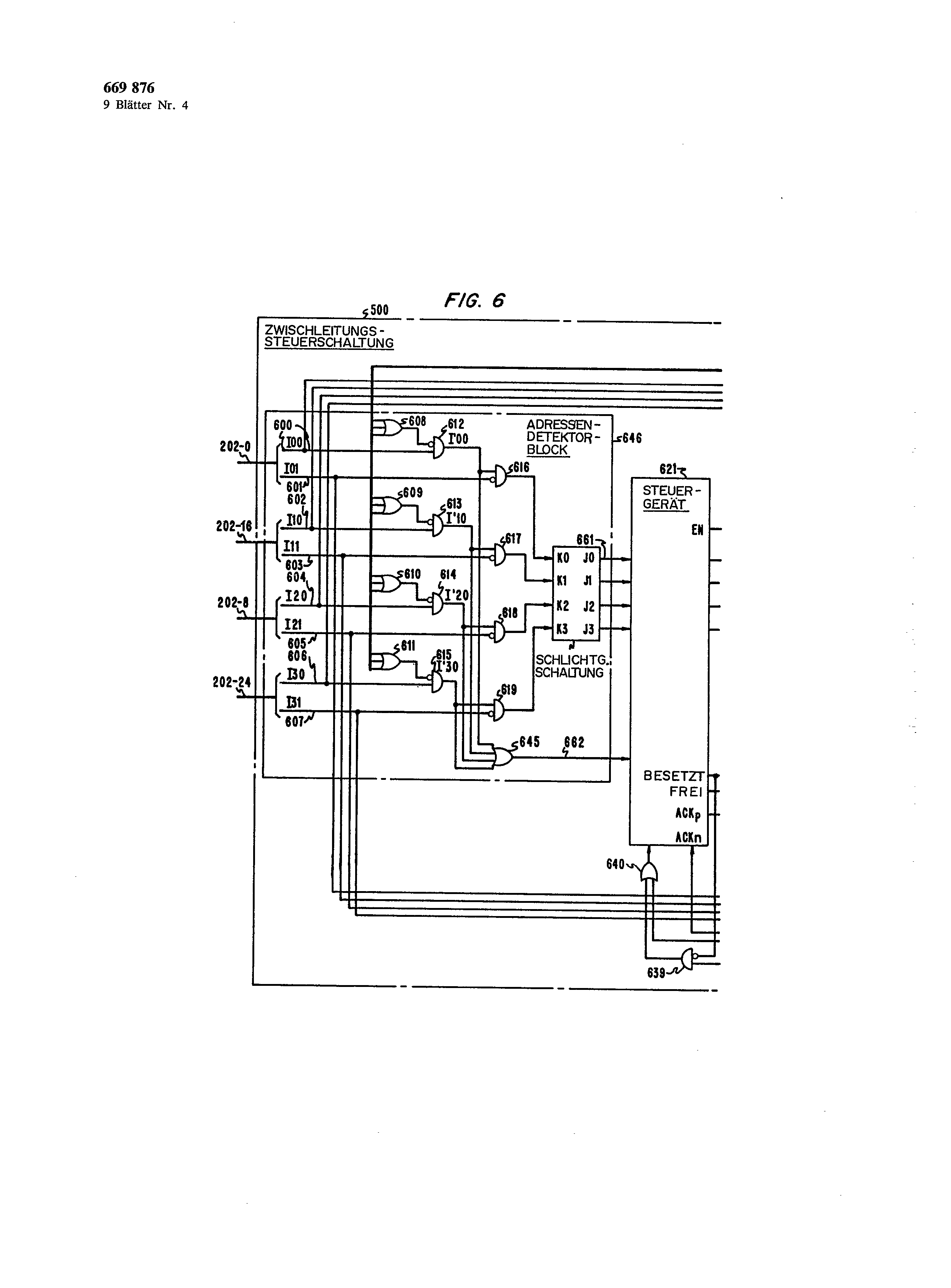
The link gate circuit 500 is more exact in the Fig. 6 and 7 represented. The link gate circuit 502 has identical structure. The link gate circuit 501 and 503 deviate in its structure however in such a way that the lower entrance of the gates 616 to 619 is not a negating entrance, since these link gate circuits respond to the fact that the address bit a 1 ist.
In accordance with Fig. each link two veins exhibits 6 and 7, for example possesses the link 202-0 the veins 600 and 601. As indicated above, each of the four link gate circuits of a knot can be independently in one of four conditions, i.e. free, constructs, to wait and occupies. If the link gate circuit is in the busy condition, the two veins of each link transfer both the data information to the Zwischenleitungssteuers0 circuit. In the busy condition a vein (straight vein) transfers all straight data bits, for example to DO, and the other vein (odd vein) transfers all odd data bits, for example to DI. In the free, Aufbauund the two veins of a given link however us serve waiting status terschiedlichen purposes and as straight and odd vein are designated. For example the vein 600 becomes as I00 (straight vein) and the vein 601 as I0 for the link 202-0! (odd vein) bezeichnet.
The link 202-16 points the veins 602 (Il0, straight óo vein) and 603 (IL! , odd vein) up, the link 202-8 the veins 604 (I20, straight vein) and 605 (I21, odd vein) up and the link 202-18 the veins 606 (I30, straight vein) and 607 (I31, odd vein) up. During the structure condition the outgoing Verbindungslei6s tuugs controller transmits a structure signal during six clock pulses of the plant on the straight vein and the address information for the same length of time to the odd Ader.
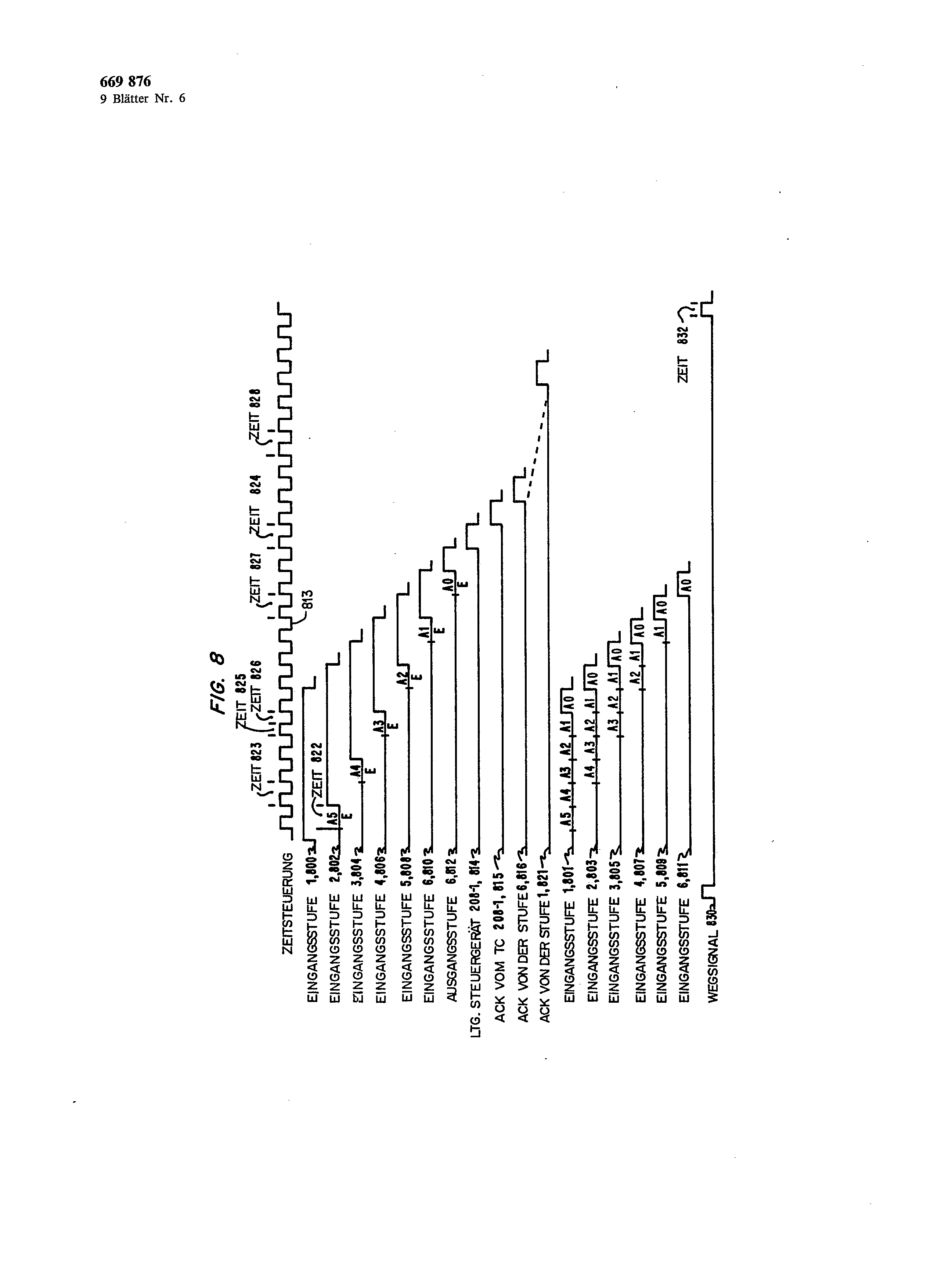
Fig. 8 shows transfers, which take place between the six stages on the straight and odd veins during the time of structure of way. In accordance with line 813 the plant clock supplies the fundamental timing for the switching nodes in the six stages. The way signal in accordance with line 830 defines the beginning of the time of structure of way. At the beginning that transfers feeder line controller 207-0 the information in accordance with line 800 and 801 to the switching node 100-0 over straight and/or odd vein the link 200-0.
During the time 822 the address detector circuit of the knot addresses 100-0 on the structure signal in accordance with line 800 and queries the address bit AS, 0, which will receive 1 on the odd vein and as input signal of the stage on the line 801 is shown. The switching node 100-0 transmits all following information, which will receive 207-0 on the odd and straight vein from the feeder line controller, under responding to this information to the selected knot in the stage 2, beginning at the time 823. The structure impulse and the address bits become over the stages according to the representation in the lines 802 to 8! 2 übertragen.
To be described as later still more exactly soli, the most significant address bit removes in each stage of the knots. For example the stage 1 removes the address bit A5. Since the address bit A5 in the stage I was removed, the receiving knot takes up the address bit A4 in the stage 2 according to the representation to line 803 at the same time with the receipt of the structure signal in accordance with line 802. In accordance with line 8! 2 the knot transfers in the stage to 6, which receives the information on the odd and straight vein, these information at the time 824 to the feeder line controller 208-1. This controller returns a confirmation signal on the odd vein under responding on the structure signal. The confirmation signal becomes then over all switching stages according to the representation in the lines 815 to 821 the Verbiudungsleitungs controller 207-0 back-transfers. If this controller takes up the confirmation signal over the stage 1, it begins with the transmission of the Paketdaten.
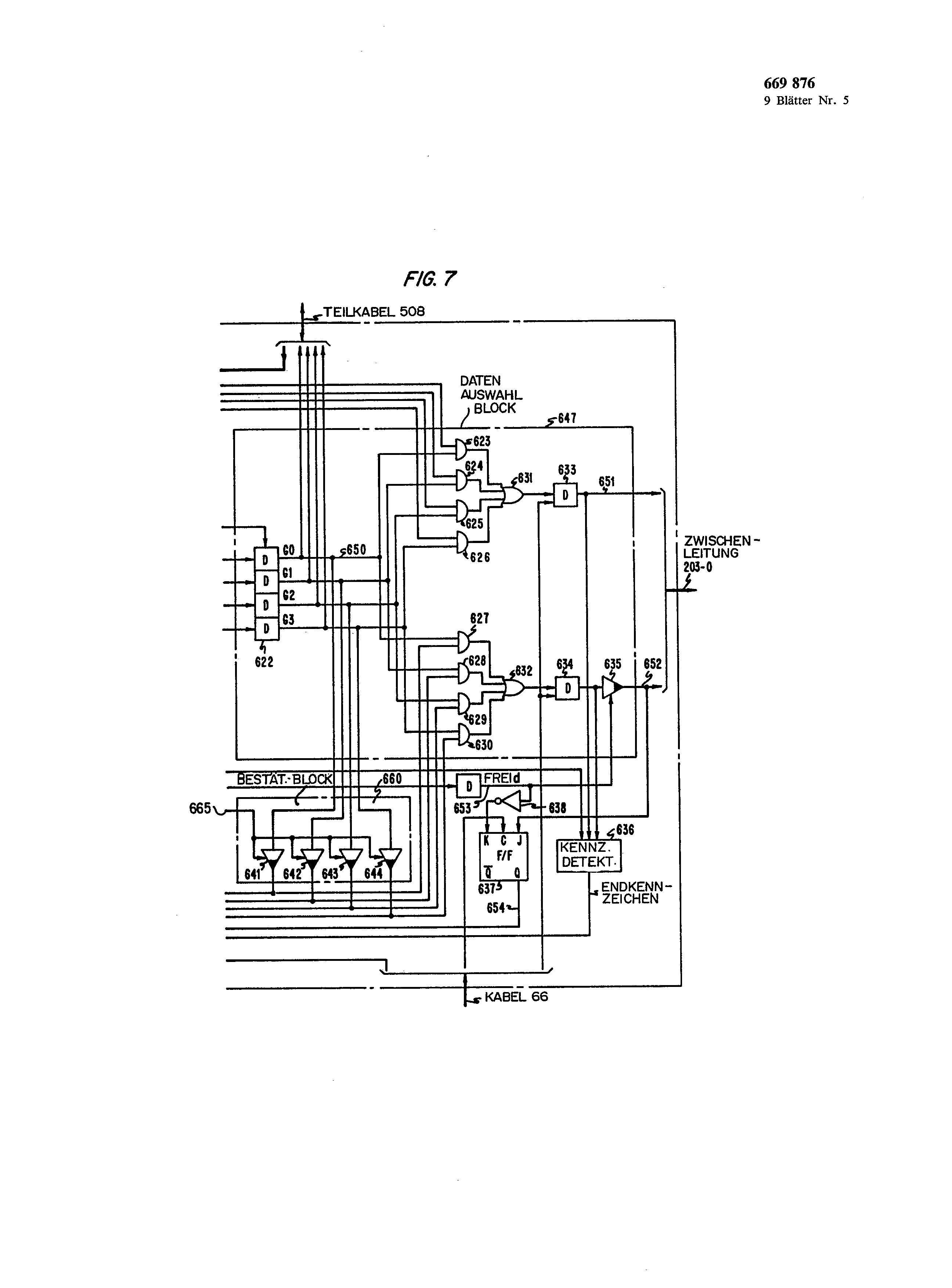
It is now the function of the Zwischenleitungsstêuêrschaltung 500 in Fig. 5 according to the representation in Fig. 6 and 7 regards. The Zwischenleitungssteuerschaltuugen 501 to 503 is similar in the structure. Their differences are to be pointed out during the following description. The controller 621 accomplishes the Steuerfunktiouen for the Zwischeuleituugssteuerschaltung 500. The address detector block 646 determines the occurrence of the address bit received over one the turned on Zwischeuleitungen during the structure condition and guarantees that no other link gate circuit of the pair of knots transmits at this moment data for this special link. In addition the address detector block 646 determines the end of the structure condition, in order to arrange the controller 621 too, into the waiting status überzugehen.
The address detector block 646 states that the structure condition past is, if it the structure signal no more empfängt.
The data selection block 647 transmits information from a selected link to the outgoing link 203-0 to the link gate circuit 500. The data selection block 647 steps during the structure condition after decoding the first bit of the address information into Tätigkeit.
It is then stated that the link steering wheel attitude 500 the remainder of the address information and the structure signal transfer to the link 203-0 to sol1. In addition the data selection block 647 steps during the busy condition into activity, around the data information from the selected Eingangszwischenleituug to the link 203-0 to übertragen.
During the waiting status the data selection block 669,876,647 is however not active and transfers no bits on the link 203-0. In the waiting status the link gate circuit 500 expects the confirmation signal of the stage 4 over the vein 652 of the link 203-0.
The characteristic detector 636 arranges the controller 621 under responding on the receipt of the end identifier in the data information to go into the free line condition. The controller 621 transmits the confirmation signal received from the stage 4 using the confirmation transmission block 660 back to the stage 2.
As indicated is the case for the above example, it is accepted that the information in accordance with line 804 in Fig. 8 on the vein 600 (straight vein) of the link 202-0 and the information in accordance with line 805 in Fig. 8 on the vein 601 (odd vein) to be received. Furthermore it is accepted that the link gate circuit is 500 in the Prei condition. This gate circuit addresses 600 and 601 at the time 825 on the information on the veins, and the link gate circuit 502 addresses 826 at the time. This Unterschíed in the points of response time avoids overlap problems between the link gate circuits. In order to determine, whether any other link gate circuit responds to information data or information of structure of way, it supervises the gate 608 of the address detector block of 646 signals of the other three link gate circuits, in order to guarantee that these circuits receive at this moment no package data or information of structure of way about the link 202-0. The monitoring is accomplished by the OR gate 608, which addresses GO of the Zwischenleitungssteuerschaltungeu 501.502 and 503 on the status bits. The bits will transfer 622 to the gate 608 to the buffer over the cable 508 from buffers similarly. If the output signal of the OR gate 608 is 0, then this indicates that the link is not active concerning the transmission of package data or information of structure of way in another link gate circuit of the pair of knots. Since the address bit on the vein 601 0 is (A3 on the line 805 in Fig. 8), über.
the exit of the gate 616 carries a 1 to the Schlichtuugsschaltung 620. A gate similarly the gate 616 in the link gate circuits 501 and 503 addresses only then in the address address A3, if this is a 1. The exits J0 to J3 of the conciliation circuit 620 depend on the conditions of the entrances K0 to K3 according to the following equations:
J0 = K0 Jl = K0 K1 J2 = K0 K1 K2 J3 = KOK1K3K3 the conciliation circuit 620 transfers a 1 with a 1 at their K0-Eingangsgatter 616 over the vein 661 to the controller 621. Under responding to a 1 on the vein 661 the controller 621 leaves the free line condition, is involved into the structure condition and stops the bit location GO of the buffer 622 to 1. Then a 1 is transferred over the vein 650 to Gartern 623 and 627, thereupon those in the following on the veins 600 and 601 transferred information to the veins 651 and 652, i.e. the veins of the output link 203-0, about the gate 631, which gate 632, which gives flip-flops 633 and 634 as well as the gate 635. In addition the attitude of the bit GO is transferred in the buffers 622 over the partial cable 508 to the link gate circuits 501.502 and 503, in order to indicate that the link 202-0 selected by the link gate circuit 500 ist.
The transmission of following information by the data selection block 647 goes far up to the time 827.
Then the gate 645 of the address detector block 646 determines that the Zwischeuleitungssteuerschaltung does not receive 500 no more the structure signal on the vein 600, and gives this circumstance representing signal 0 over the vein 662 to the controller 621. This goes thereupon into the waiting status. When entering this condition the controller 621 prepares the link gate circuit 500 for the admission of the Bestätilo gungssignals from the stage 4. The controller 621 transmits a signal OPENd over a delay pure direction 670 and the vein 653. In addition this signal closes the gate 635 against a transmission on the vein 652 and places the flip-flop 637 zurück.
If the actuation signal of the stage 4 at the time 828 arrives, the flip-flop 637 is adjusted. Its exit Q transfers a 1 over the vein 654 to the controller 621. Under responding to the 1 on the vein 654 the controller 621 transmits the confirmation signal back to the stage 2 and enters the busy condition. This endaround carry of the confirmation signal to the stage 2 takes place via endaround carry of a 1 by means of the vein 655 to gates 641 to 644. Since the output signal GO is a 1 and this will transfer 650 on the vein, the gate gives a confirmation impulse on the vein 601 back to the stage 2. to 641 in addition the signal OPENd the data selection block 647 makes possible by manipulation of the gate 635, data on the vein 652 too übertragen.
If those of link steering wheel ΠEhaltung 500 no confirmation signal over the vein 652 of the stage 4 the time ago 832 in accordance with line 830 in Fig. , is brought the controller 621 receives 8 by the receipt of a signal of the OR gate 640 and of and gate 639 with receipt of the way signal by the gate 639 obligatorily into the free line condition. The only reason for it that a confirmation signal does not return from the stage 4, consists of the fact that it was not possible to develop a way to the feeder line controller 208-1. The circumstance that the controller 621 by the way signal over the OR gate 640 is brought and and gate to 639 into the free line condition, guarantees that the controller 621 not on indefinite time in the waiting status bleibt.
In the busy condition the controller 621 transmits all in the following 601 data arriving on the veins 600 and to the veins 651 and/or 652. At the same time the transferred data are supervised for the statement of the end identifier. If the end identifier is determined by the characteristic detector 636 (by the occupation signal one operates), then this circumstance indicating signal goes over the OR gate 640 to the controller 621. This steps under responding on the arriving end identifier into the free line condition ein.
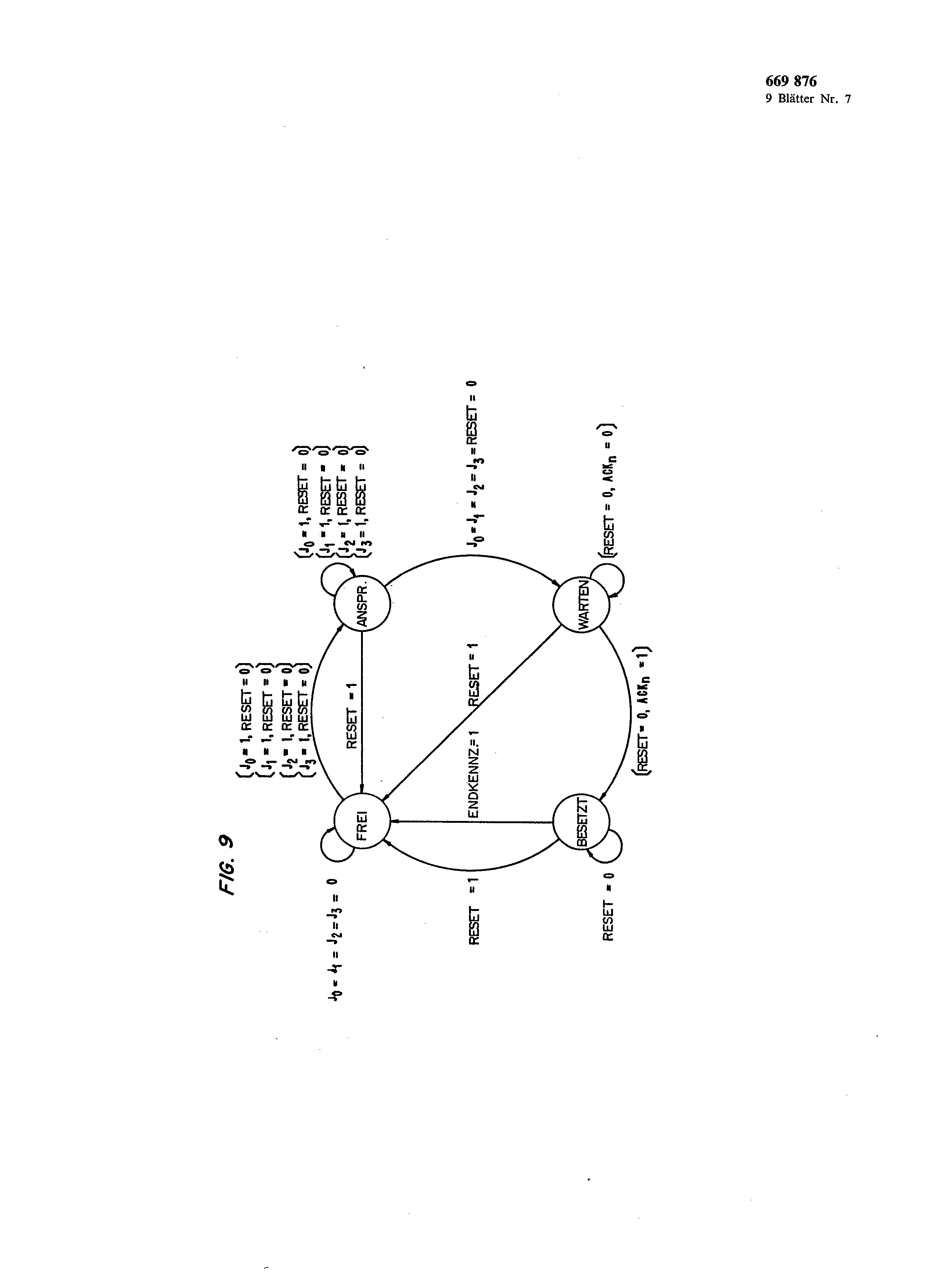
Fig. the state table for the controller 621 shows 9. The table defines the total operation of the controller 621 in detail.
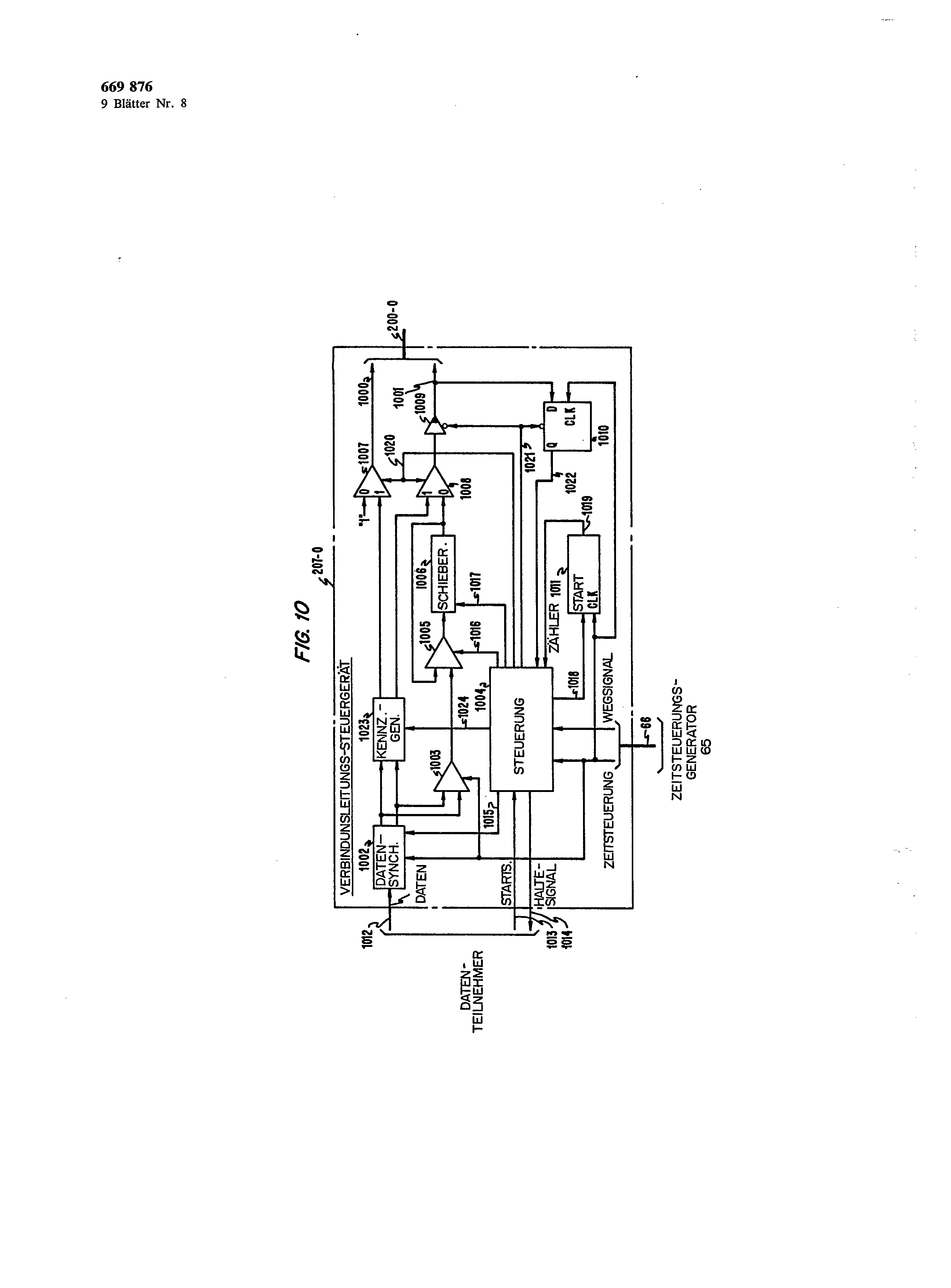
The feeder line controller 207-0 is in Fig.
represented. It responds to data, which were received from a data division taker, and transmits these data to the switching network in accordance with Fig. 2. If with the data division taker data line up for a transmission, the data division taker gives the starting signal to 1013 over the vein for control 1004. Under responding to the starting signal the control transmits 1004 the retaining signal over the vein 1014 to the data division taker and leads those in the following from the data division taker transmitted data over the cable 1012, a data synchronisation circuit 1002, a parallel series transducer 1003 and a data voter 1005 to the shift register 1006. The control 1004 manufactures this way by transmission of appropriate signals on the veins 1015, 1016 and 1017. In addition the control 1004 starts a counter 1011 for the counting of six bit times, which represent the 669,876 8 six address bits, which from the data division taker received and into the shift register 1006 transferred werden.
After line-to-store transfer of the six address bits in the shift register 1006 the control transmits 1004 the retaining signal over the vein 1014 to the data division taker. The transmission of a 1 on s of the vein 1019 by the counter 1011 for control 1004 informs these of the fact that dii six addr eating bits are stored in the Sehieberegister 1006. At this time the control is 1004 in a waiting status, until the timing generator 65 produces the way signal. With the receipt, o of the way signal prepares the control 1004 the data voters 1007 and 1008 for the admission of data over its 0-Eingänge and transfers the address bits stored in the shift register 1006 over the Datenwählter 1008, the gate 1009 and the vein 1001 to the link 200-0. At the same time, since the data voter 1007 selected his 0-Eingang, a signal is spent 1 on the vein 1000. This signal is the Aufbausignal.<br described above/>
After the six address impulses under controlling of the counter were sent 1011, scolded the control 1004 the gate off 1009, operate the flip-flop 1010 and wait for the confirmation impulse returning over the vein 1001. With receipt of the confirmation impulse the control sends 1004 a signal over the vein 1014, which informs the data division taker of it that he can continue the transmission of data. After completion of the transmission either a package or from data running over a normal connection the data division taker terminates sending the starting signal over the vein 10l 3. when stopping the starting signal gives the control 1004 over the vein I024 a signal to the characteristic generator 1023, which arranges the generator to send the bits of the end identifier over the data voters 1007 and 1008 as well as the veins 1000 and/or 1001. Under responding to this end identifier the knots on the manufactured way give these frei.
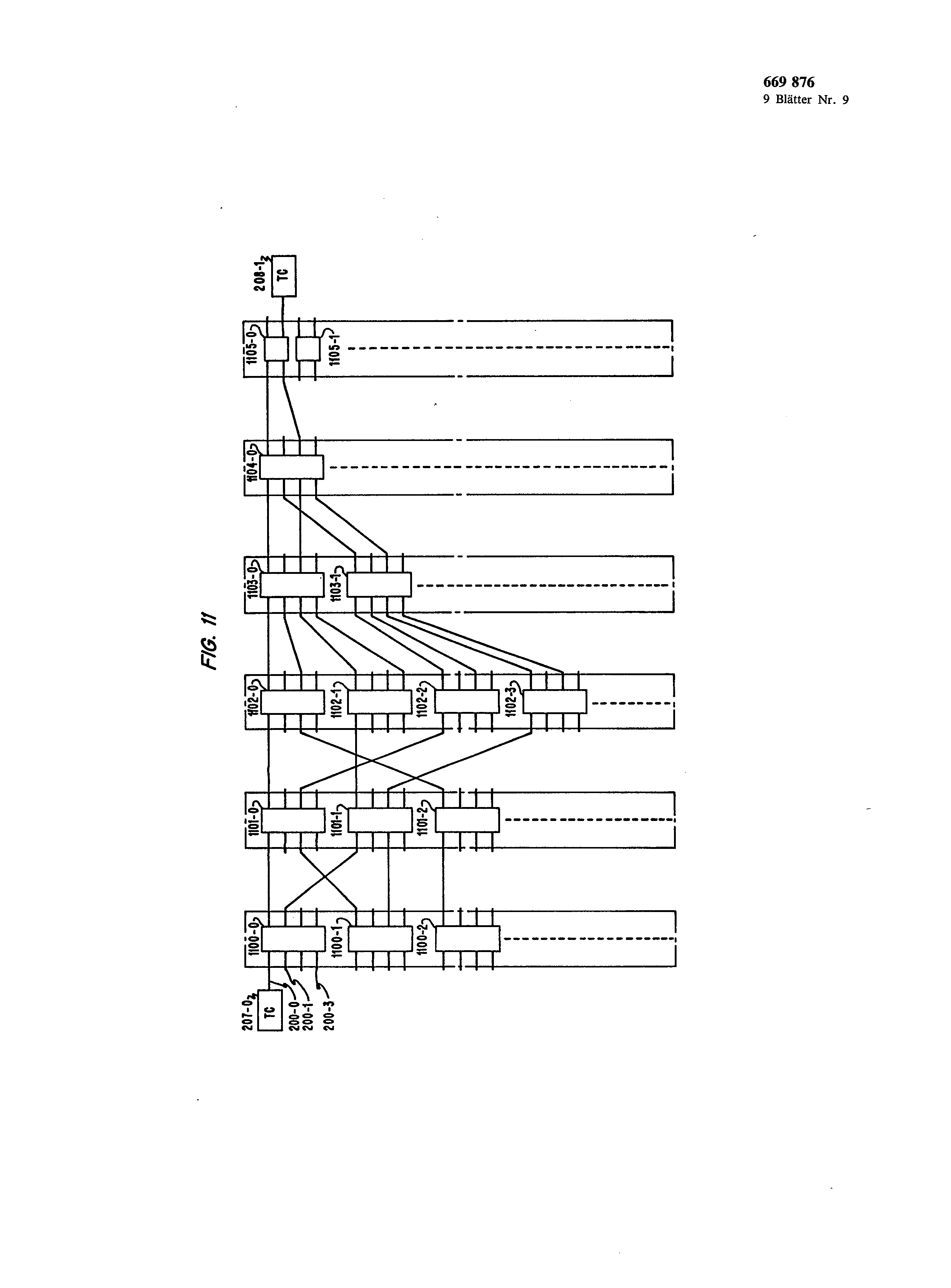
To the adjustment of the structure in accordance with Fig. 2 to an implementation with the help of the Grossintegrafion (VLSI) is a topological transformation of the structure in accordance with Fig. 2 necessarily, in such a manner that all pairs of switching nodes take a neighbouring position. The topological transformation is in Fig. 11 represented, whereby pairs of knots are shown as individual Bauteli. The designation is in such a way selected that the reference symbols of the construction units of the lowest numeric designation of the first switching node in Fig. 2 corresponds. For example the pair of knots is 102-0, 102-4 of the stage 3 in Fig. 2 in Fig. , and the pair of knots 101-1, 101-3 designates 11 with 1002-0 in accordance with Fig. 2 is with 1101-1 marked. The topological transformation is defined as follows: Since the telephone exchange network work was transformed in such a way that two switching nodes, which see traffic to divide, lie together is the Schiebefunkfion S1 for the execution of this operation for the knots of the ith stage in Fig. 2 after shifting the new position of the link [Pri, -. - PiPi-1… P2 P1 P0] defines too:
, 5 SI [tPn,… Pi+, PiPiPi,… P2 P, P0]] = [Pri-1 -. - Pi+1 pi,… P2 PIPiP0] whereby i = 2,3…. n/2.
It sci SI--1 the inverse function of SI. Then is valid:
SI '[[pH,… PI+IPiPi-1… P2 P, P0]] = [pH,… Pi+IP1 pi-i… P2 P0].
Ti is defined as follows:
Tj [[Pn_I… Pi+1 PiPi i… P2 P1 P0]] = [pn-i… Pi+1 P0 pi-i… P2 P1 pi].
Di is the topological rule, which defines, like Zwisehenleitungen of knots of the ith stage with the links of knots (i + l) - stage are connected and Di = do-i.<br ten/>
The topology of Fig. 2 is given by Si+1DiSi-I.
The above-described remark example is to only show the basic ideas of the invention. Other Anordhungert can be used by the specialist. Thus the specialist recognizes easily that for the case i > m/2 (m = number of the stages in the network and i = level number) the knots in a given section of the ith stage in some way to be in pairs arranged können.
v of 9 sheets designs 200-0 200-46Æ 200-49 STAGE 1 I I I i I I I I I I e I I I STAGE 2 I I I I I I I FIG. 1 STAGE 3 I I I I I I i STAGE 4 | I I I I I I STAGE I I STAGE 6 06-0 205-4 61 A communication method and self-routing switching network interconnecting a plurality of interface controllers for communicating packets and circuit switched information via multiple paths within the self-routing switching network. The latter comprises stages of switch nodes that are grouped into pairs. The stages are interconnected by links and each pair of switch nodes shares the same set of input links from the preceding stage. In response to receipt of address information from a destination interface controller transmitted via a link, a pair of nodes determines one of a multitude of paths through the switching network by one of the pair responding to the address information to communicate the address information to the next sequential stage after establishing a path through that particular switch node. Once a path has been established through the switching network, an acknowledge signal is transmitted back through the network to the destination trunk controller indicating that the path has been established. The path remains established until the end field of the packet is detected or the proper end information is transmitted after transmission of the circuit switched information. The architecture of the switching network is such that no additional switch nodes are required beyond what would be required in a conventional self-routing network. 1. An alternate-path, self-routing, packet and circuit switching system for switching packets for a plurality of messages and circuit switched information from a plurality of digital data units, said system comprising: a switching network having a plurality of stages each comprising sets of a plurality of switch nodes; a plurality of distributed controllers each for interfacingly connecting an individual one of said digital data units to one set of said switch nodes; each of said controllers responsive to a received one of said packets and a start of circuit information for transmitting address signals to establish a path through said switching network; each switching node of a set of said switch nodes of one stage being interconnected to another set of switch nodes in the next sequential stage; and one switch node of a set of said switch nodes responsive to receipt of said address signals for setting up said path via another one of said set of switch nodes in said next sequential stage. 2. The system of claim 1 wherein each of said packets comprises an end flag field containing signals indicating the end of the packet; and each set of said switch nodes comprises means responsive to the receipt of the end signals for removing said path through said switching network. 3. The system of claim 1 wherein each of said controllers comprises means for transmitting end signals upon the completion of the communication of said circuit switched information; and each of said switch nodes comprises means responsive to the receipt of the end signals for removing said path through said switching network. 4. The system of claim 3 wherein said one of said set of said switch nodes further comprises means for designating another one of said other set of switch nodes in said sequential stage in response to said address information; means responsive to a communication unavailable signal from said designated other one of said other set for entering an idle state; and said one of said set of said nodes further comprises means responsive to said communication unavailable signal for transmitting another communication unavailable signal to the last preceding stage. 5. The system of claim 4 wherein said one of said set of said switch nodes further comprises means responsive to receipt of said address signals for transmitting an input link busy signal to the other switch nodes of said set containing said receiving switching node; and said other switch nodes of said set responsive to receipt of said input link busy signal for entering an inactive state with respect to said path. 6. The system of claim 5 wherein said receiving one of said set of said switch node further comprises means responsive to said address signals to eliminate the most significant address signals and to retransmit the remaining address signals to the next sequential stage. 7. A self-routing switching network for communicating information messages in response to address routing information from network input ports to network output ports, said network comprising: a plurality of switching stages interconnected by transmission links; each of said stages comprising sets of a plurality of switch nodes with all nodes of one individual set of nodes being connected to all links of one individual set of said links from a preceding stage for distributing the communication messages received on said set of links throughout said switching network so that the traffic capacity and reliability of said network is increased; and one of a set of nodes responsive to said address routing information on one of said links of said set of links for establishing a path through said switching network. 8. The switching network of claim 7 wherein said set of nodes comprises two nodes and the configuration of said set of nodes is defined by complementing bit positions of a binary number representing the stage position of said one of said nodes of said set to obtain another binary number representing the stage position of the other node of said set. 9. The switching network of claim 7 wherein said set of nodes comprises two nodes and the configuration of said set of nodes is defined by a pair of binary numbers each representing the position of an individual node in said stage; one of said numbers represents the position of said one node of said set of said stage; another of said numbers representing the position of the other node of said set defined by complementing the bit position of said one of said numbers equal to the stage number of said stage where the stage number is less than or equal to half the total number of stages in said network; and said other of said numbers defined by complementing the least significant bit position of said one of said numbers where said stage number is greater than half of said total number of stages. 10. The switching network of claim 7 wherein said set of nodes comprises two nodes and the configuration of said set of nodes is defined by a pair of binary numbers each representing the position of an individual node in said stage; one of said numbers represents the position of said one node of said set of said stage; another of said numbers representing the position of the other node of said set defined by complementing the bit position of said one of said numbers equal to half the total number of stages minus the stage number plus one where the stage number is less than or equal to half the total number of stages in said network; and said other of said numbers defined by complementing the least significant bit position of said one of said numbers where said stage number is greater than half of said total number of stages. 11. An alternate path, self-routing, packet and circuit switching system for switching packets for a plurality of messages and circuit switched information from a plurality of digital data units, said system comprising a plurality of switching stages; a plurality of transmission links interconnecting said stages; each of said stages comprising sets of a plurality of switch nodes; all nodes of one individual set of nodes being connected to all links of one individual set of said links from a preceding stage for distributing said packets and circuit switched information received on said set of links throughout said switching network so that the traffic capacity and reliability of said network is increased; a subset of said set of nodes responsive to said address routing information of one of said links of said set of links for establishing a path through said switching network; and said subset of said set of nodes responsive to end signals contained in one of said packets for removing said path through said switching network. 12. The invention of claim 11 wherein said system further comprises a plurality of distributed controllers each for interfacingly connecting an individual one of said digital data units to one of said switch nodes; each of said controllers comprises means for transmitting end signals upon the completion of said circuit switched information; and each of said switch nodes responsive to the receipt of the end signals for removing said path through said switching network. 13. The system of claim 12 wherein each set of nodes comprises two nodes and the configuration of said set of nodes is defined by complementing bit positions of a binary number representing the stage position of one of said nodes of said set to obtain another binary number. 14. The switching system of claim 12 wherein each of said sets of nodes comprises two nodes and the configuration of said sets of nodes is defined by a pair of binary numbers each representing the position of an individual node in said set; one of said numbers representing the position of one node of said set of a stage; another of said numbers representing the position of the other node of said set defined by complementing the bit position of said one of said numbers equal to the stage number of said stage where the stage number is less than or equal to half the total number of stages in said network; and said other of said numbers defined by complementing the least significant bit position of said one of said numbers where said stage number is greater than half of said total number of stages. 15. The switching system of claim 12 wherein each of said sets of nodes comprises two nodes and the configuration of said sets of nodes is defined by a pair of binary numbers each representing the position of an individual node in said set; one of said numbers representing the position of one node of said set of a stage; another of said numbers representing the position of the other node of said set defined by complementing the bit position of said one of said numbers equal to half the total number of stages minus the stage number plus one where the stage number is less than or equal to half the total number of stages in said network; and said other of said numbers defined by complementing the least significant bit position of said one of said numbers where said stage number is greater than half of said total number of stages. 16. A method of switching packets and circuit switched information through a switching network comprising a plurality of switching stages interconnected by transmission links, each of said stages comprising sets of a plurality of switch nodes with all nodes of one individual set of said switch nodes being connected to all links of one individual set of said links from a preceding stage, and comprises the steps of: transmitting routing information on one of said links of said set of links to establish a path through said switching network; selecting one of a multitude of paths through said network by one of a set of said switch nodes responding to said address routing information to transfer said address routing information to another set of switch nodes in the next sequential stage. 17. The method of claim 16 wherein said switching network further comprises distributed controllers interconnecting digital data units to said switching network and said set further comprises the steps of one of said controllers transmitting end signals upon all circuit switched information having been transmitted; and disenabling said path by each of said switch nodes upon receipt of said end signals. 18. The method of claim 16 wherein said selecting steps further comprises the steps of transmitting an input link busy signal to the other switch nodes of said set by said one of said set of said switch nodes; entering an idle state with respect to said path by said other switching nodes in response to receipt of said input link busy signal; and establishing said path to the next sequential stage by said one of said set of said switch nodes.