Hydraulic jack
The invention concerns a hydraulic jack gemãss the generic term of the requirement 1st that hydraulic jack can for example as mobile jacking equipment dienen.
Acquaintance mobile, hydraulic jacking equipment possess a rack with án this stored Rädem a pump with a Pumpeñkolben, which is vemchiebbar with a pedal or, manually tiltable Betãtigungshebel, a cylinder, by a Hydrauiikflüssigkeit in this verschîebbaren Kolban by this liftable load carrier a sowîe drain valve, in order to make by discharging hydraulic fluid from the cylinder a lowering possible of the load carrier. The drain valve points a shutoff device: up, through the tricks more eíner with it connected spindle provided with an external thread; mchtwinldig to the horizontal drag axis of the. Pedal as well as the lever verstel! bar.ist. A Winkelgetriebe exhibits a Ûbertragungsorgan with a gear wheel, drehfest mentioned swivelling around the drag axis, and with this continuously in the interference standing gear wheel fastened to the spindle. The pumping lever is formed from one, pipe, in which a regulating unit with a gear wheel knows held istù the regulating unit against: Kraft at it of an attacking: Feather/spring into a position verschoban become, in that its gear wheel with the gear wheel of the Ûbertragungsorgans in the interference stands and in that the shutoff device of the Ablassventi! s by manual rotation of the regulating unit to be adjusted kann.
The production of a spindle with a Aussengewínde, one with this cooperating internal thread as well as the gear wheel fastened to the spindle and assembling these parts as well as adjusting rderliche when assembling e are verhäitnismässig complex. Besides a Winkelgetñebeinsbesondere is if its gear wheels ni very exactly Versch strong in the intended positions installed be-being one! eiss subjected and störanfällig.
The invention: the task is the basis to create a hydraulic jack the disadvantages of the well-known jacks repairs and with that in particular the means for adjusting the shutoff device of the Ablãssventils möglìchst economically manufactured as well as to be assembled can and more betñebssícher funktionieren.
This task is solved by a hydraulic jack, which exhibits the characteristics of the requirement i according to invention. Favourable one. Arrangements of the jack go out of the dependent requirements hervor.
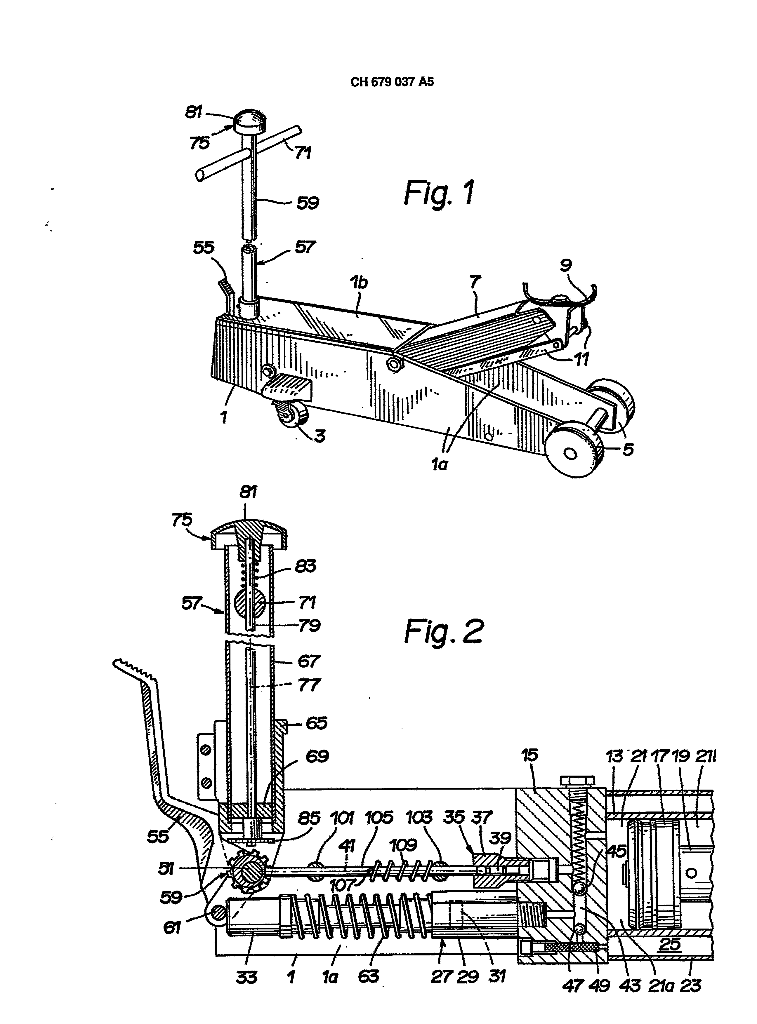
The invention article is more near erlåutert in the following on the basis a Ausfûhrungsbeispiels represented in the design. In, the design shows the Rg. 1 a diagonal view of a mobile, hydraulic jack:
the Fig. 2 a Vertikaischnitt by some parts of the jack drawn in the Fìgm 1, the Fig. 3 a cutout from the Fig. 2 in more largely yardstick, whereby different parts were omitted, the Rg. 4 a plan view from above on in the Fig. 3 evident parts of the Kurvengetñebes of the jack as well as a string plate drawn on average of the rack lifting and the Fig. 5 a cut dumh the bearing bolts serving for storing the transmission equipment of the Kurvengetñebes .und for storing other parts along the line V-V of the Fig. 4.
In the Fig. 1 evident, mobile, hydraulic jacks serves as jacking equipment and is for example for lifting up to 1; 0 tons of amounting to loads trained. Hydrau! a Iãngliches rack I with two vertical, to each other parallel side plates exhibits ische jacks la, a Deckplafte lb and other parts. Two wheels 3 are in the proximity itself in the Fig. 1 on the left of finding, front end of the rack 1 ever freely. over held around a vertical axle drehbãr or at least tiltable at the Gestall I for its part, at the rear end of the rack two wheels 5 are freely swivelling stored a horizontal axle swivelling in a fork stored, which is. Load-carrier-lift [7 is on, nem an end around a horizontal axle tiltable at the rack a 1 stored. At the other end of the load carrier lever 7 a load carrier 9 is tiltable stored around a horizontal axle. Two steering wheels 11 are linked ever with an end at the rack a 1 and with the other end at the load carrier 9 and form together with the load carrier lever 7 a Parallalfûhrung for the load carrier 9.
In the Fig, 2 a part of a cylinder 13, i.e. a Hebeoder of actuator evident for lifting the load carrier 9, is. The cylinder 13 and .ein this at the left end concluding final part are fastened to the rack I. A piston 17 is led horizontal adjustable in the cylinder 13, divides its interior 21 into two ranges 21a, 21b and is connected by a piston rod 19 with the load carrier lever 7. To the cylinder a 1; 3 coaxially, these enclosing coat 23 limited together with the cylinder 13 a reservoir 25 fOr a Hydraulikflûssigkeit, a pump 27 a housing 29, which fastens turned away side of the final part of 15 on that the interior 21 solvable to this, possesses i.e. to the Teli into a tapped hole eîngeschraubt is. The housing 29: aussan to the Teli a hexagonal Umñssform has: possesses however a zylindñschen cavity and forms thus a pump cylinder, in which a piston 31 parallel to the piston 17 adjustably led and with a piston rod 33 is connected. A drain valve exhibits solvable a housing fastened to that the interior 21 turned away side of the final part of 15, in which an adjustable shutoff device 37 is adjustably led along one to the shift directions of the pistons 17 and 31 parallel axle 41. The final part of 15 contains a passage 43, which connects the Inneñraum of the housing 29 of the pump 27 by in it existing, branched out several times, a spring-tensioned ball exhibiting skirt impact valve with the range 21a of the Innen2 3 CH 679,037 A5 4 of area 21 existing between the final part of 15 and the piston 17 and by a check valve 47 as well as a filter exhibiting a ball 49 with the reservoir 25. The range 21b of the interior 21 finding on the turned away side of the piston 17 is not connected for the final part by eíne evident connection with the reservoir 25. Sích the section of this, existing between the check valve and the delta of the passage 47 flowing into the interior range 21a, a not visible feeder line, which are formed by a passage possibly existing in the final part of 15 also still at least partially, with the reservoir 25 by one alternatively schliesssowie is connected to freigebbaren passage of the drain valve and. The shutoff device 39 of the drain valve 35 is back and forth adjustable between two end positions, in which it closes and/or releases the passage of the drain valve. The drain valve 35 is trained for example in such a manner that the pressure is anxious it over a section of the passage from the range 21a of the interior 21 supplied and at its shutoff device 39 attacking hydraulic fluid to press the shutoff device 39 from the Innenrãum 21 away into that end position in which the shutoff device 39 at the valve seat or an other Anschlagfiäche lines up and which passage of the drain valve closes, d.h.
liquid absperrt.
At the two side plates la the rack 1 is in larger yardstick in the Fig. 3, 4, 5 evident bearing bolt 51 rigidly fastened, the one pedal 55, a lever 57 and transmission equipment 59 around a horizontal drag axis 53 tiltable stores, which crosses the axle 41 right-angled. The pedal 55 forms from each other separated, vom= filled storage hurrying for bearing bolt 51 in its lower Teli a fork with two by a gap. At these is underneath the bearing bolt 51 right-angled to the shift directions of the pistons 17, 31 more vedaufonder, than driver fastens 61 serving pin, with which the pedal at the piston rod 33 of the pump 27 attacks. If a person swivels the upper end of the pedal downward of 55 with one her feet around the drag axis 53, this shifts the piston 31 of the pump 27 over the piston rod 33 against the resetting force produced by one at this attacking feather/spring 63 to the cylinder 13. The lever 57 possesses forming storage hurrying penetrated by the Lagerbclzen, which is on the exteriors both storage hurry of the pedal 55 at its lower end an owner 65 with two together a U-förmjge fork. The owner 65 possesses furthermore a case, into more softly the lower end of a pipe 67 is fastened. In this pipe 67 a disk 69 is fastened with a hole coaxial to the pipe, a handle 71 consisting of a straight staff penetrates the pipe 67 in close proximity to its practicing rem end, is fastened and likewise provided with a hole coaxial to the pipe to the pipe in close proximity to its lower end. The lever 57 knows senkrechten position, in which its owner 65 at by a cut of the cover plate lb or an attack formed lines up to an other part, on the basis of one at least approximately by a person manually forward - thus in the Fig. 1 and 2 to the left - and around the drag axis 53 to be swivelled downward. The owner 65 attacks thereby at the pedal 55, so that this is likewise downward swivelled and with its driver 61 the piston rod 33 and thus the piston 31 of the pump 27 verlo schiebt.
A regulating unit 75 possesses the Lõcher of the disk 69 and the handle 71 penetrating and of this along an axle 77 axially adjustably led as well as around this axle 77 swivelling stored wave 79, whereby the axle is right-angled 77 to the drag axis 53. At the upper end of the wave 79 a reset knob 81 is fastened. A feather/spring 83 encloses the section of the wave 79 finding between the Handgrifi 71 as well as the reset knob 81 and exercises themselves of the bearing bolt 51 as well as of the transmission equipment 59 Kraft away arranged on the regulating unit 75. Particularly clearly in the Fig. 3 evident gear wheel 85 has on the lower end of the wave 79 sitting and with a pin 89 at this fastened hub 87.
The Stellcrgan 75 is from first, in the Fig. 2 as well as 3 drawn sliding end position, in which its hub 87 at the disk 69 lines up, against the resetting force into a second sliding end position, produced by the feather/spring 83, adjustably, in which the reset knob 81 at the pipe 67 ansteht.
The Ûbertragungsorgan 59 is in such a manner between both storage hurrying of the pedal 55 located on the bearing bolt 51 that it when swivelling: 35 of the lever 57 and/or pedal 55 one does not along-move by these. Like it particularly clearly in the Fig. , possesses the upper carrying organ 59 a gear wheel 91 is evident to 3, 4, 5 and from a separate workpiece formed, rigidly with the gear wheel 91 connected, i.e. with this welded hub 93. The gear wheel 91 is designed directly as the gear wheel 85 as front gear wheel, whereby teeth of the two gear wheels are in such a manner constituted however that they can comb with one another, although the axles of the two gear wheels right-angled to each other are. The hub 93 consists arranged socket or disk with circle-cylindrical of one eccentrically to the gear wheel 91 outlined. The gear wheel 91 and the hub 93 possess with one another escape-end, by the bearing bolt 51 filled, for the center of the gear wheel of 91 konzentñsche holes 91a and/or 93a, i.e. cylindrical drillings. The cylindrical extent surface of the hub 93 forms a Führungstlãche 93b, which is naturally curved on average right-angled to the drag axis 53 and forms a circle. The hub 93 is provided on their dern gear wheel 91 turned away face with one to the hole g3a parallel blind hole 93c. In this parallel to the drag axis 53 a stop pin 95 outstanding from the hub 93 is fastened, i.e. pressed in rigidly. The bearing bolt 51 is provided on that the gear wheel 91 turned away side of the hub 93 with a continuous cross-perforated hole 51a consisting of a drilling. In this a AnCH 679,037 A5 6 impact pin 97 is fastened by pressing in, its two ends from the bearing bolt 51 stands out immovable and by this: with the rack 1 is connected. The two stop pins 95, 97 form together slinging means, those the angle, around that the transmission equipment 59 drohbzw.
, to a value limits, less than 360° and at the most 180° is tiltable beträgt.
If the Anschlagstìft in accordance with 97 the Fig. 5 by the drag axis 53, is even somewhat smaller the angle mentioned runs than 180o.
At the two Sêitenplatten la the rack 1 51 two ever guiing devices 101.103 consisting of a pin are fastened between the drain valve 35 and the bearing bolt. Each of these eìn its longitudinal axis possesses right-angled crossing Fûhrungsloch consisting of a continuous drilling, that with the Fûhrungselement 101 in the Fig. 3 as well as 4mit 101a is characteristic. In the Fûhrungslöchem of the two Fûhrungselemente 101, 103 is led from a straight bar of existing slidegate valves i05 in such a manner adjustably that its longitudinal axis coincides with the axle 4,1, along which the shutoff device 39 of the Ablassvenfils 35 is adjustable. The slidegate valve 105 is provided with a continuous cross-perforated hole, in which with both ends from this outstanding pin is fastened 107. A feather/spring 109 encloses the section of the slidegate valve 105 finding between the Fûhrungselement 103 and the pin 107, feels at the pin 107 and presses the slidegate valve against the hub 93 gehöronde to the Ûbertragungsorgan 59, so that an end of the Schiebere 105 against the guidance surface 93b of the hub 93 rests. The Ûbertragungsorgan 59 and the slidegate valve 105 form together a Ku_rvengetriebe, by which turnings of the Ubertragungsorgans 59 41 shifts of the slidegate valve 105 running around the drag axis 53 in along the axle rechtwìnkligen in addition are converted kõnen. If one swivels the transmission equipment 59 97 end positions fixed between its two by the stop pins 95, back and forth, the slidegate valve is back and forth shifted between two end positions. As well as the end positions of the slidegate valve 105 thus indirectly by to the transmission equipment 59 fastened around the drag axis 53 bezûglich the rack 1 being certain stop pin 97 specified tiltable stop pin 95 and that. Into the Fig. 2, 3, 4, drawn end positions of the Ubertragungsorgans 59 and the slidegate valve 105, with those the stop pin 95 at itself in the Fig. and the slidegate valve 105 furthest from the cylinder 13 as well as next with the drag axis 53 lines up to 5 on the left of finding end of the stop pin 97 is, in the following as first end positions of the transmission equipment 59 and/or, slidegate valve 105 is designated. The other end positions of the transmission equipment and slidegate valve, in those the stop pin 95 at itself in the Fig. and the slidegate valve 105 next with the cylinder lines up to 5 on the right of finding end of the stop pin 97 13 as well as furthest from the drag axis 53 distant is, as second end positions is designated. The slidegate valve 105 rises up with its transmission equipment turned away end into the housing 37 hinein.
The length of the slidegate valve is in such a manner limited the fact that it angreìft at least in its first end position either not at all at the shutoff device 39 or no Kraft on this exercises and itself the shutoff device in its passage of the drain valve 35 closing end position befindet.
If the Ûbertragungsorgan 59 is swivelled on the basis of RST of its first end position into seíne second end position, it shifts the slidegate valve 105 from the drag axis 53 away more deeply into the housing 37 of the Ablassventìls inside. The slidegate valve 105 attacks then at least during the last part of this shift movement with its transmission equipment 59 turned away end at the shutoff device 39 and shifts this against the thrust force expenditure-practiced by the hydraulic fluid on the shutoff device into a position, in that the shutoff device the passage of the drain valve 35 freigibt.
If a person the hydraulic jack b - to use wants, it can go to these through or drive a pushing at the handle 71 of the lever 59 cars which can be lifted into the desired position under one or other article which can be lifted. Afterwards the person can alternatively abverschwenken with a foot the pedal 55 or with the hands the lever 59 aufund and thus the pump 27 betãtigen. This pumps thereby Hydraulikfiüssigkeit from the reservoir 25 to the range 21a of the interior 21, whereby the piston 17 by the final part 15 is away-shifted and over the piston rod 19 the load carrier lever 7 as well as by this load carrier held the 9 upward swivels. The Ûbeñragungsorgan 59 and the slidegate valve 105 are to be when pumping naturally in their first end positions, in which the drain valve 35 is closed. The jack serving person Nässt the reset knob 81 when pumping freely, so that the feather/spring 83 the regulating unit 75 of the bearing bolt 51 of the drag axis 53 as well as the 0bertragungsorgan 59 away to in the Fig. 2 and 3, first sliding end position gazeichñete drûckt, in which the two gear wheels 85, 81 stand from each other uncoupled sînd, i.e. except interference. In this uncoupled condition of the two gear wheels lagging of the lever 57, with which the regulating unit and its gear wheel 85 are along-swivelled, does not cause movements of the transmission equipment 59.
If the load carrier 9 soli, seizes the jack serving operator the reset knob 81 with a hand, presses the SteUorgan against 75 the Rûckstellkraft produced by the feather/spring 83 to the transmission equipment 59 into the second sliding end position of the regulating unit and thereby the gear wheel brings 85 in interference with the gear wheel 91 is lowered. The Bedinungsperson can turn now the regulating unit 75 manually around the axle 77 bzw.
swivelled and thus the transmission equipment 59 as well as the slidegate valve 105 in their second end positions move and the drain valve open, so that Hydraulikfiüssigkeit flows out of the interior Bereìch 21a of the cylinder 13 into the reservoir 4 7 CH 679,037 A5 8 and lowers themselves the load carrier 9. The stop valve remains then independently of it, whether the operator presses the regulating unit 75 to the transmission equipment 59 and thus the two gear wheels 85, 91 in interference holds or whether the regulating unit releases the operator and is uncoupled the two gear wheels 85, 91, openly, until the transmission equipment swivels 59 manual pressing of the regulating unit 75 again into the first end position wird.
Of the transmission equipment 59 and the slidegate valve of 105 formed cam gears is economically producible and simple as well as at least approximately without adjusting work mountable. Far the cam gear is sturdily, reliable in service and insensitive on Verschmutzungen.
The hydraulic jack can be changed in different regard. The drain valve can be arranged for example in such a manner trained as well as that it is closed if its shutoff device is in its furthest position distant from the drag axis 53 as well as the Ûbertragungsorgan 59. Furthermore it is possible to connect the shutoff device of the drain valve rigidly or with limited Spie parallel to its shift direction] with the slidegate valve of the cam gear so that the slidegate valve from the transmission equipment do not only force the shutoff device away, for sondem also to this moves kann.
It consists even the possibility of forming the shutoff device and the slidegate valve attacking at the curved guidance surface of the Ubertragungorgans together of a einstückigen body. Far the slidegate valve at its can be provided the transmission equipment turned end with a freely swivelling stored role, those when swivelling the transmission equipment on its curved guidance surface unreels kann.
Instead of connecting the slidegate valve as with the drawn Ausführungsbeisp.iel by the feather/spring 109 actuated with the Übertraguñgsorgan 59, the slidegate valve can be connected furthermore formsehlüssig with the transmission equipment, by equipping it with Gleitem or roles, which attack at each other turned away sides of the transmission equipment at its guidance surface, which the bearing bolts can do 51 penetrating and the drag axis 53 crossing stop pin 97 furthermore it is shifted in such a manner and arranged eccentrically to the drag axis that the transmission equipment is tiltable around one exactly 180° amounting to angle. Furthermore one can plan two separate in place of one with both ends from the bearing bolt of outstanding stop pin, bezûglich the rack being certain stop pins and/or two separate with the transmission equipment connected as well as together with this varyable stop pins and/or replace the stop pins by different attacks…. to far the slidegate valve shifting guidance surface can instead of from a Kreiszylindertlãche eccentric to the drag axis of the Ubertragungsorgans of only along a Teli of a circle] up-end surface or any differently curved surface exist, the one curve running along a level rechtwinldigen to the drag axis of the transmission equipment forms and their distance from the drag axis along the curve ändert.
Far one knows the Stim Zahnrä, which 85, 91 by Kegei gear wheels to replace. Furthermore also the slinging means serving for the definition of the sliding end positions of the regulating unit can; on or other kind to be changed. Far the hydraulic jack can be possibly trained instead of s of mobile jacking equipment also as transporting and lifting pallets. Besides the hydraulic jack can be designed even as not mobile jack. The jack comprises a frame (1), a cylinder (13), a piston (17) displaceable by means of an hydraulic fluid, and a pump which can be actuated alternatively by a pedal (55) or a manually pivoting operating lever (57). In addition a discharge valve (35) is provided, the shut off device (39) of which is displaceable by means of a control member (75) held by the operating lever (57), via a cam drive comprising a transmission member (59) which can be pivoted about the same pivot axis as the pedal (55). The operating lever (57), and a slider (105) which can be displaced across a curved guiding surface of said transmission member. The cam drive is economical to manufacture and to assemble and is operationally reliable. 1. Hydraulic jack with a rack (1), a cylinder (13), in this piston (17), adjustable by a hydraulic fluid, a pump (27) to pumping the hydraulic fluid, one around a horizontal drag axis (53) tiltable lever (57) for operation of the pump (27), one with the interior (21=) of the cylinder (13) connected, right-angled adjustable a Abspermrgan (39), to the drag axis (53), exhibiting drain valve (35), one of the lever (57) held, bezûglich this manually movable Steùorgan (75) and a transmission, by the regulating unit (75). .um the drag axis (53) tiltable Ubertragungsorgan (59) exhibits and is trained, in order to convert turnings from this in adjustment movements of the shutoff device (39), by the fact characterized that the transmission eín cam gears with one of the 0bertragungsorgan (59) gebi! - deten, kurvenfõrmigen guidance surface (93b) and one with the shutoff device (39) connected, to the Fûhrungsflãche (93b) slidegate valves (105) angrsifenden ist= 2. Jacks according to requirement 1, characterized by slinging means (95, 97), those the angle, around which the 0bertragungsorgan (59) is tiltable, on less than 360° amounting to value limit. 3. Jack according to requirement 2, by the fact characterized that the Ansohlagmittel (95, 97) firmly firmly exhibits at least one with the rack (t) connected attack (97) and at least one with the Ûbertragungsûrgan (59) connected attack (95). 4. Jack after requirement 2 or 3, by the fact characterized that firmly with rack (1) more connected, which lever (57) and 0bertragungsorgan (59) storing bearing bolt (51) available is that the slinging means (95, 97) fastened one in a continuous cross-perforated hole (51a) of the bearing bolt (51) as well as beìdenends from this outstanding stop pin (97) and one to the drag axis (53) parallel, in a hole (93c) of the transmission equipment (59) fastened as well as from this outstanding stop pin (95) exhibit and that the transmission equipment (59) between two end positions is tiltable, with those at the Ubertragungsorgan (59) 9 CH stop pin (95) fastened 679,037 A5 to or other end of the stop pin (97), fastened in the bearing bolt (51), steht.
Jack after one the speech 1 to 4, by the fact characterized that the guidance surface (93b) at least one part: one to the drag axis. (53) of exzentríschen circle forms. 6. Jack after one of the requirements,2 to 4 and according to requirement 5, by the fact characterized that the slinging means (95, 97) limit the angle mentioned on one hõchstens for 1.80= amounting to value. 7. Jack after one the Ansprûche 1 to 6, whereby at the Gesteli (1) a that. Betãtigungshebel: (57) as well as ûbertragungsorgan (59) storing bearing bolt (51) held is verschíebbar, the Ste Iorgan (75) against Kraft of a feather/spring (83), attacking at it, along one zw drag axis (53) right-angled axle of first into a second end position as well as around this axle (77) is swivelling and a gear wheel (85) exhibits, that in the first end position of the Stel! organ (75) from one to the Ûbertragungsorgan (59): uncoupled ìst uñd în the second Êndstellung of the position man (75) with this apartment wheel (91) in in it stands for belonging gear wheel (91), by the fact characterized that practice gungsorgan (59): one rigidly with the gear wheel (91), belonging to it, connected, for example from a separate workpiece formed and with this gear wheel (91) vemchweisste, filled by the bearing bolt (51), the Fûhrungsfläche (93b) i forming hub (93) aufwei=. 8. Jack after one of the requirements 1 to 7, by the fact characterized that at the slidegate valve (105) this against the Führungsflãche (93b) oppressive feather/spring (109) angreift.