Gumption device for band-shaped material.
The invention concerns a Schneidvordchtung f0r bandfSrmiges material after the generic term of the PURPOSE: To provide a cutting device requiring less space, and having a long service life by moving a movable blade to a closed position to an end stop on one side first, and holding the movable blade at the position till it is also at a closed position on the other side. CONSTITUTION: A counter blade 3 is fixed in a groove 4 in a base 1. Two pivots 5, 6 compose rotatable coupling between the counter blade 3 and the base 1. A movable blade 7 has an extended part 8, and it is in contact with the counter blade 3 at any position. A clockwise eccentric plate 22 is used for driving, and its rotary motion is transmitted to a holding body 11 as process motion through a connection link 23. A stopper 21 stops process motion on the side where a cutting device is first closed. By motion of the eccentric plate 22, resistance of a spring 18 resists the blade holding body 11, and the blade holding body 11 moves to a closed position. The movable blade 7 closes gap to the counter blade 3 like scissors to cut a film. Completion of the Schnittes.
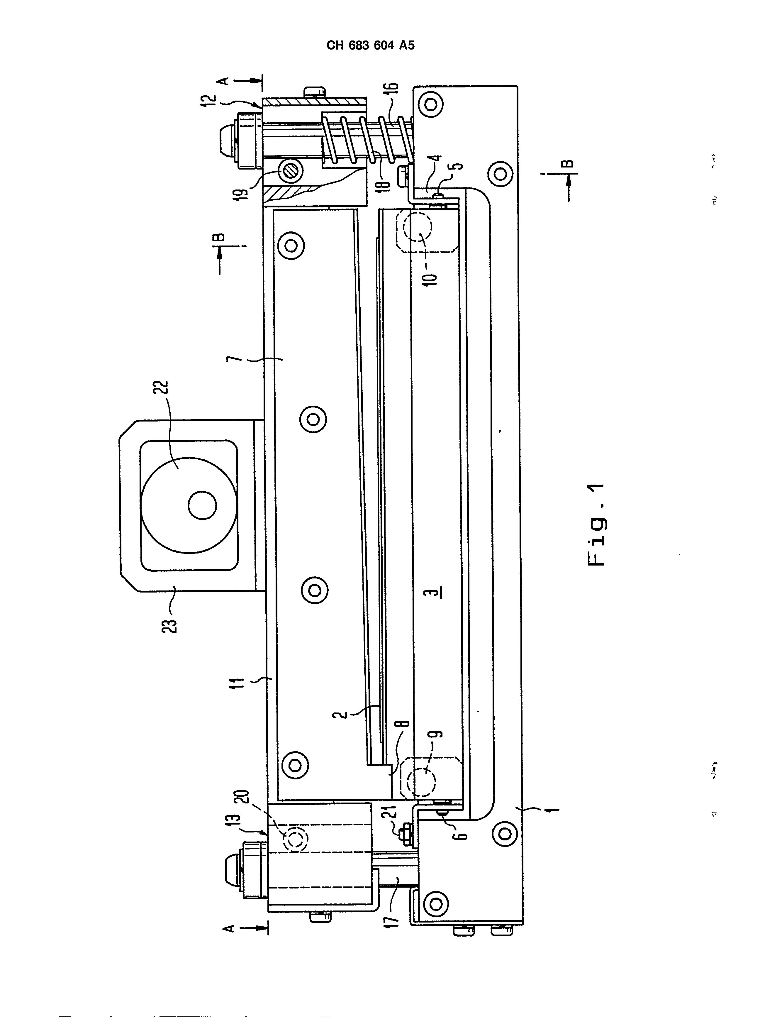
The gumption device consists 1, which serves the transport of the bandfSrmigen material 2 of a Tr gerplatte. The Gegenmesser 3 is fastened in a slot 4 of the plate 1. Two taps 5 and 6 form a swivelling connection between Gegenmesser and plate. The run measurer the 7 is provided with an extension 8, which rests in each position against the Gegenmesser 3. The Gegenmesser is subjected by the feathers/springs 9 and 10 toward the run measurer. The run measurer the 7 is fastened elnero measurer owner 11, the gabelf6rmige of final ranges 12, 13 exhibits on. Into the schlitzf0rmigen C) 14, 15 ffnungen these final ranges is the bearing journal 16, 17 gef0hrt more stationer connected with the plate 1. A feather/spring 18 st0tzt itself between the plate 1 and the measurer owner 11 off. The lateral F0hrung of the measurer owner 11 at the bearing journal 16, 17 0bernehmen two Lagerrellen 19, 20, which are connected in this Ausf0hrungsbeispiel stationarily and swivelling with the measurer owner 11. AIs drive serves a clockwise rotating eccentric cam, whose rotation becomes by the backdrop 23 as Hulm movement on the measurer owner 11 0bertragen. The attack 21 soil the stroke on the side of the gumption device closing first stoppen.
erfindungsgem& ssen gumption device dargestellt.
With the beginning to the movement of the measurer owner the strength of the feather/spring 18 opposes 11 to the stroke, which becomes by the eccentric cam 22 ausgel0st. The measurer owner moves therefore first on the side into its closed position, against which the run measurer 7 already with its extension 8 the Gegenmesser 3 rests. The Schliessbewegung is stopped on this side by the last detent 21. In the case of further turn of the eccentric cam 22 now the feather/spring becomes 18 zusammengedr0ckt and the slot between run measurer 7 and Gegenmesser 3 closes shear-like toward the bearing journal 16 spring-tensioned. Thus thereby a relative motion already results to the Gegenmesser 3. in the case of closing the Laufwegung toward the bearing journal 17,
By erfindungsgem& sse device is hrleistet a shear-like cut 0her the entire width of the bandf6rmigen of material 2 with high service lives for the run measurer the 7 and the Gegenmesser the 3 gew. Invention in accordance with sse gumption device does not build thereby more largely as so far gebr& uchliche Schneidvorrichtungen.
PatentansprOche 1. Gumption device for bandf6rmiges material, in particular for B#.nder made of photo paper or for films, with a measurer arrangement, which at least a mobile run measurer and at least a standing Gegenmesser exhibits, thereby characterized that a drive is intended, that the run measurers first on a side up to seinero the last detent into the closed Stel] ung moved and in such a way is enough in this position stop, until the run measurer likewise is with his other side in the closed position. 2. Gumption device according to requirement 1, by it characterized that exhibits run measurers outside of the width of the volume on the side, which can be cut, which is moved first into its closed position an extension, st& ndig against the Gegenmesser rests. 3. Gumption device according to requirement 1 or 2, by the fact characterized that run measurers and the Gegenmesser are kept gegenseifig by flexible means in plant. 4. Gumption device according to requirement 1, by the fact characterized that as drive a rotary, eccentrically mounted role is intended, which is gefOhrt in a backdrop, the which with an owner for run measurer connected ist.
Gumption device according to requirement 4, by it characterized that the run measurer to the Seire, which is moved last into its closed position a resistance is opposite, the gr6sser is as area-deer-ends moment from the cut friction and the gumption strength. 6. Gumption device according to requirement 5, by the fact characterized that the resistance is a feather/spring. 7. Gumption device according to requirement 1, by the fact characterized that the owner is designed for mobile run measurers at its two ends gabelfSrmig, in particular as slot with a FOhrungsl nge yon at least a F0nftel the width of the material volume, and ever with the Geg.enmesser of connected station of rer taps in the Offnung intervenes. 8. Gumption device according to requirement 7, by it characterized that into the gabelf0rmigen ends of camp roles are intended, itself in the insides station& ren taps abst0tzen. 9. Gumption device according to requirement 8, by the fact characterized that at least one of the camp roles outward spring-tensioned ist.
Gumption device according to requirement 8, by the fact characterized that with fixed distance of the camp roles the ussere distance h0chstens equal the hchlen width between station& ren tap is. 11. Gumption device according to requirement 1, by the fact characterized that exhibits run measurer an easy bend, so that it in closed position only with its & against the Gegenmesser rests to usseren ends. 12. Gumption device according to requirement 1, through it characterized that exhibits run measurer a hollow grinding, and that two Gegenmesser are intended, which a slot for depresses the run measurer form. 13. Gumption device according to requirement 1, by it characterized that the Gegenmesser exhibits a hollow grinding, and that two run measurers are intended, which on both sides the Gegenmessers gegenl it is ufig moved.