Salt cleaning equipment.
The available invention concerns a device for the cleaning of solids, in particular yon crystalline solids, consisting of particles, gem&ss generic term of the patent claim 1.
Salts, to the Beispie! Sodium chloride, in salt cleaning equipment yon Frerndstoffen be pray-ridden, before they are processed or used in the industry. The kind of the impurities h ngt strongly from the production process and veto production place of the salt off. Acquaintance uses either vacuum recrystallisation or rnechanisches washing tqeinigungsverfahren rnit a Waschfl0ssigkeit, for example with water. The first Veffahren is expensive and for special's applications is only used. The second procedure exhibits a relatively small efficiency, there the Waschfi0ssigkeit in the cleaning equipment several times circulated and thus ever more berets washed impurities beinhaltet.
Remedy will be lt thereby created that this Frerndstoffe purposefully verd0nnt or assistance of chemical Zus&tzen from the salt caustic solution ausgefa]. The Verd0nnen and the use yon chernischen Zus&tzen erh6hen however the manufacturing costs of the salt substantially. A further reason for the small efficiency are the salt losses, which are caused by the fact that itself a Tell of the salt crystals in animal WaschflOssigkeit aufl6st.
F Jr the salt cleaning retained themselves a procedure and a device of the Anmelderin, which under the name SALEX't admits sind.
Predivide this procedure are the deep operating cost, the verb series efficiency in view to the attainable degree of purity of the salt and the very low Salzverluste.
SALEX' - procedure is based to a hydraulic extraction with a ges&ttigten L6sung on the principle of the Gegenstrornreinigung, with which removes foreign matter and divided and gel6ste SalzkristalJe will zurGckgewonnen by urge crystallization. In a simplest variant of the procedure the salt which can be cleaned calls itself hydraulic extractor downward verj6ngenden Beh#.lter, into a kegelf6rmigen, gef011t. Force of gravity-caused the salt the Beh<er durchrieselt from top to bottom. In opposite direction rnindestens ann hernd pure, ges ttigte brine is eingefuhrt into the hydraulic extractor, which fiiesst upward along the hinunterrieselnden salt crystals, impurities yon the salt crystals 16st and rnit upward f0hrt. The cleaned salt is led separately from the hydraulic extractor into a centrifuge, incoming goods the salt crystals yon the partial downward along-demanded brine werden.
Preferring way is more rnrnbeh<er durchgeffJhrt before the hydraulic extraction a Schl&mrnung in the hydraulic extractor a placed in front Schl. This Schl&mmbeh more ller points itself likewise a kegelformige, downward verj (Jngende form up, so that the salt the Beh durchrieseit likewise becomes more lter from top to bottom in opposite direction an impure, ges&ttigte brine in the Schl mmbeh more lter eingef (Jhrt, which separates insoluble impurities from the Salzkristalten and with upward f0hri.
Between Schl mmung and hydraulic extraction will prefer-proves a hydraulic classification to go through. The hydraulic classification, i.e. classification rnit impure brine, errn0glicht the distance of fewer 16slichen Fremdstoiten, zurn example of calcium sulfate. This hydraulic classification takes place in the AIIgemeinen irn upper range of the hydraulic extractor, so that itself in the hydraulic extractor of reason tzlich zwoi cleaning ranges, an upper Hydreklassifikationsraurn and a lower crystallization area, more exactly Hydroextraktionsund Verdr ingungskristallisationsraum, bidden.
In a further variant of the procedure the salt crystals are cut up before the Schl rnmung vorg&ngig by Scherund/or hydraulic cutting. The hydraulic cutting as well as the shearing cutting break salt crystals open rnit eingeschlossehen foreign particles in the connection places with the Frerndstoffen and set these foreign particles frei.
The Salex; - Procedure in its different variants is not only for salts, but generally for from particles existing Feststotfe, in particular for crystalline solids, anwendbar.
Qbwohl this procedure and the hierf6r used hydraulic extractor good results obtains, must the plant nevertheless more imrner again stillge] be egt, since the Hydre extractor clogs. A cause hierf0r is that the salt in the hydraulic extractor crystallizes to gr0sseren Klurnpen. In the consequence irn hydraulic extractor Kan&le are formed, which exhibit a gr6sseren Durchiluss as the Qbrigen of ranges in the Beh more lter. Thus the FI0ssiganteil into the centrifuge arriving and from the centrifuge of the ausstr6menden of salt becomes too hoch.
Furthermore further procedures and devices are well-known, which likewise on a Gegenstrornprinzip beruhen.
Thus DE-A-1 describes 294,344 a device to the continuous the Auswa mother liquor from solids, with which the WaschflL is led upward ssigkeit yon down, w thrend the solid which can be cleaned yon is above admitted and due to the force of gravity dutch the Waschfl0ssigkeit sinks downward and waiter a Ausfluss6ffnung is derived. It is necessarily that the Waschfl0ssigkeit the solid if possible g] calibrationmassively interspersed, whereby the solid slowly drops soil.
Standing, cylindrical Reinigungsgef ss, a perpendicularly for Urn this to reach, is used which exhibits for solids che in the lower part an installation element in form of a Absetzfl. The discharge opening range of the Gef of sses below the Absetzfl - che is arranged kegeiformig. The inlet of the WaschflQssigkeit rniJndet irn small distance Liber or under these Absetzfl&che into the Reinigungsgef ss. With this procedure] ediglich a small Tell of the Waschfl rises (upward and verdra.ngt the mother liquor ssigkeit. The gr6ssere Tell schwemrnt the matured layer of the solid particles to the Ausfluss6ffnung this procedure exhibits a small efficiency, there the solid particles on the installation element settles and to majority serums lumps kristallisieren.
3 OH 690,840 A5 4 EP-A-0 098,637 ebenfaiis its device reveals for cleaning yon to solids a against the current. The Reinigungsgef&ss consists of a cylinder, which is divided mittens intermediate plates into several vertically 0bereinander arranged mixing chambers. These mixing chambers are connectable with one another more ber controllable valves, so that each section of the Feststoffs&ule purposefully with the ascending Waschfl (3ssigkeit to be mixed kann.
This device is relatively complex and exhibits a small efficiency, there a R0ckvermischung which can be cleaned of the solids with the WaschflQssigkeit due to the produced turbulence stattfindet.
US-A-5 068,092 describes a procedure for the cleaning of sodium chloride by means of brines and magnesium chloride brines the against the current. The Reinigungsgef&ss is arranged zylinderf6rmig, whereby it exhibits two ranges with different diameters. Daloei is the upper range with one grSss. .eren diameters provided as untere.
The Ubergangsbereich between the ranges and the discharge opening range are arranged kegelfSrmig. Both ranges exhibit Einlass6ffnungen for the counter current brines, whereby in the upper range magnesium chloride brines with a hSheren magnesium chloride content are let in as in the lower. Also with this plant the danger exists that the flow in both directions not gleichm&ssig bleibt.
It is therefore task of the Effindung to create a device for the cleaning from solids consisting of particles to which the above-mentioned disadvantages behebt.
This task of 16st a device for cleaning yon from particles existing solids, in particular of crystalline solids, with the characteristics of the patent claim 1.
The erfindungsgem&sse device I&sst not only for cleaning yon Natriumchloricl, but for the cleaning of all solids consisting of particles, in particular crystalline solids, use themselves, which according to the same principle yon contamination is separated kennel.
With the erfindungsgem&ssen device by simple structural measures Klumpenund are prevented/or channelings within the Reinigungsgef&sses. Within the solid bed formed by the solid which can be cleaned thus no Str6mungskan ile with h6herer speed arises compared with the Qbrigen ranges of the Reinigungsgef&sses. The solids str6men due to the force of gravity and under the form of the Reinigungsgef&sses gleichm&ssig, i.e. with ann&hernd same speed (Jber the entire cross section of the Gef&sses, and comparatively slowly downward toward Auslass6ffnung, which can be cleaned, whereby they wetden within all ranges of that cleaning brine umspi31t. The cleaning brine strSmt thereby at least ann&hernd gleichm&ssig upward. By the special form of the Reinigungsbeh<ers k6nnen of solids, which are only in the hydraulic classification area, not i more ber a channel directly to the Auslass6ffnung gelangerf, without by a certain retention time in the crystallization area cleaned too werden.
Besides the solids in the crystallization area, which can be cleaned, become ann&hernd at least turbulence-free of that cleaning brine umsp lt.
The efficiency, in particular the cleaning temperature, is improved and the number of the continuous operation hours of the plant is erh6ht, there the Getahr of a blockage of the Reinigungsgef&sses decreased ist.
FSr the Funktionsf&higkeit of the cleaning equipment is substantial it that in the Reinigungsbeh<er no channeling can take place. Above all the polluted cleaning brine does not daft from above waiter a channel to the AuslassSffnung downward arrives, there the pure brine within the lower range of the ReinigungsbehAIters thereby polluted warden.
The realization is invention substantial that this 1 sses by suitable choice of the form of the Reinigungsgef can be gew&hrleistet, without any special mechanical Str6mungsregler are inserted to m within the Reinigungsgef#, sses ssen the special form of the Reinigungsgef&sses, i.e. the small Konus6ffnungswinkel ermSglicht yon 100 to 30°, a gleichm&ssigen, prevents constant flow in both STR mungsrichtungen and Klumpenund channeling. The maximally attainable Konus6ffnungswinkel h&ngt yon the condition of the Innenw&nde of the Reinigungsgef&sses, the Fluidisationsgeschwindigkeit, the KorngrSsse and the Koh& sion the solids which can be cleaned ab.
Vorteilhaff during the erfindungsgem&ssen device is besides that mechanical Str6mungsreg [he within the Reinigungsgef6sses are no longer compellingly necessary. Such Str6mungsregler has only partly effective to replace usually st6rungsanf llig and in provided cleaning equipment with difficulty. A preferential AusfL) hrungsform the erfindungsgem&ssen device points therefore no inserted chicaneries or Str6mungsregler aut.
The Reinigungsgef&sse exhibits gem&ss the state of the art likewise kegelfSrmige ranges, these serves in the AIIgemeinen however to actually create a m6glichst short Ubergang of one kreiszylinded6rmigen Gef ss for the narrowed AuslassStfnung. Reinigungsgef&sse, which exhibit however an essentially kegelfbrmige form, are on a m6glichst small Bauh6he. .m6glichst large Gef&ssvolumen create. The Offnungswinkel of the cone was therefore optimized according to these criteria, and betr> with both AusfQhrungsformen 50° to 60°.
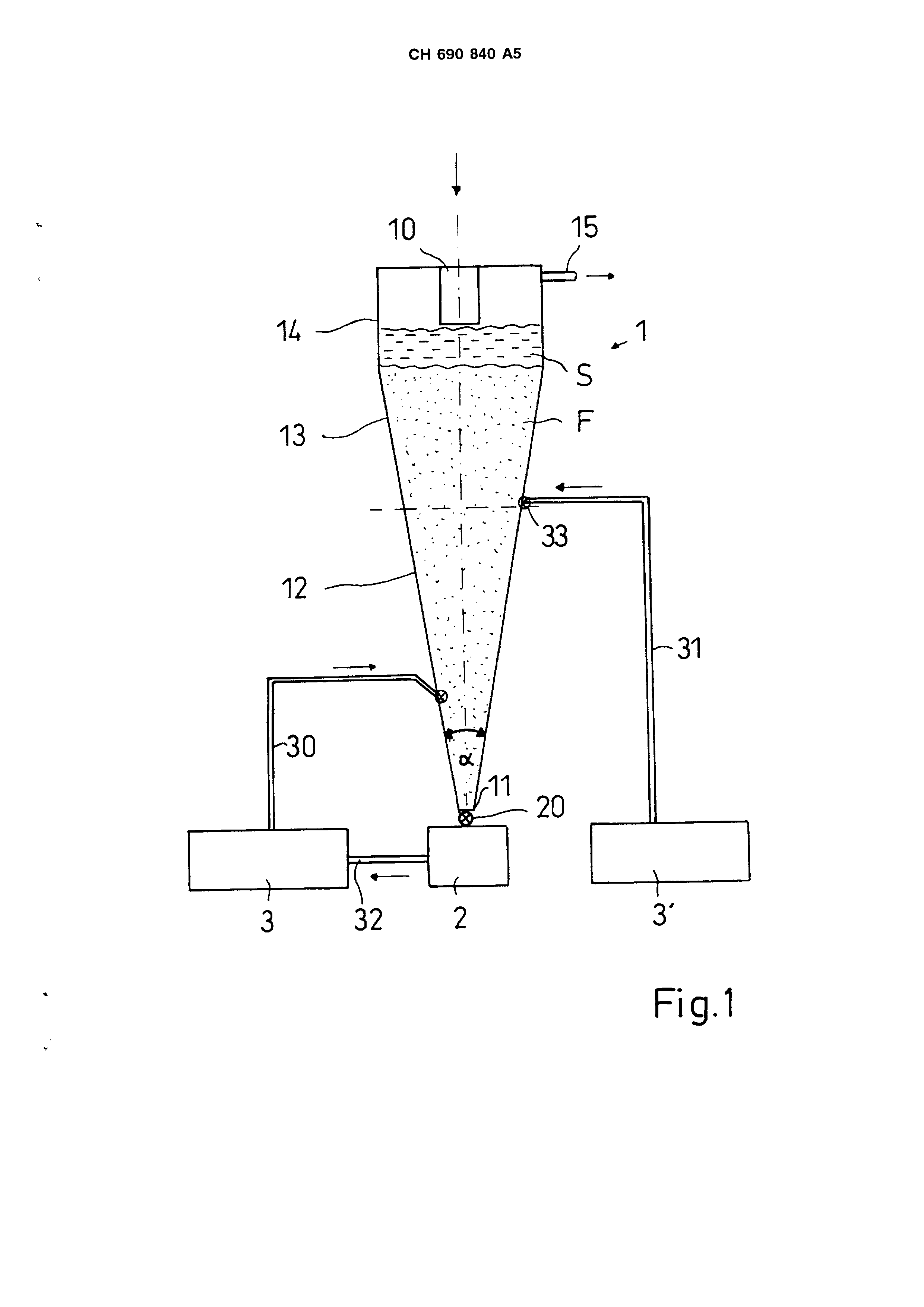
In the enclosed designs AusfShrungsbeispiele of the invention article are represented, which are erl&utert in the following description. Fig show. 1 a sehematische representation of the cleaning equipment with the erfindungsgem&ssen Reinigungsgef[!ss!] Fig. 2 a further AusfCJhrungsform of a Reinigungsgef&sses gem&ss the Effindung and Fig. 3 a schematic representation of the SALEX® procedure of the Anmelderin.
3 CH 690,840 A5 6 in Fig. 1 is a device for the cleaning of crystalline solids, here salt cleaning equipment, represented, soft prefer-proves in accordance with ss the SALEX - procedure operated is called a cleaning container 1, also hydraulic extractor, is arranged vertically standing and exhibits above a EinfOll6ffnung 10 as well as a SoleL] bedauf 15 and down a Auslass0ffnung 11. The Auslassoffnung fOhrt in this AusfL] hrungsbeispiel to a centrifuge 2, whereby in the Ubergangsbereich a controllable exhaust valve prefer-proves 20 is arranged. Anstelie of a centrifuge are other separation devices applicable, for example a Bandfilter.
Into the Reinigungsgefass 1 at least one supply line 30, 31 mLmdet for a Reinigungssole.
Each supply line 30, 31 is prefer-proves with a Reinigungssole Vorlagegef ss 3, 3 " verbunden.
In Fig. 1 represented Ausf hrungsform exhibits the Reinigungsgef ss 1 a lower, a middle and an upper range 12, 13 and 14. In this example the middle range 13 corresponds to the hydraulic classification area, where a hydraulic classification takes place, and the lower range 12 the crystallization area, in which the hydraulic extraction and the urge crystallization take place. The solid f011t in the operating condition both ranges in form of a fixed bed, consisting which can be cleaned, of individual particles, up, which is gepunklet represented in the Fig 1. Above the fixed bed F the brine S in the Betriebszusland, which by the crystallization area and/or the hydraulic classification area gestr6mt is already and now 0ber the Soleuberlauf 15 discharged wird. , is
Preferring way are present supply lines 30, 31 for a cleaning brine both in the lower as well as in the middle range 12, 13. K6nnen into the two ranges different cleaning brines with different degree of purity by way of introduction werden.
The upper range 14 of the Reinigungsbehalters is arranged kegeloder zylinderformi9, whereby in Fig. 1 the zylinderf6rmige variant Oargestellt is. It goes into the middle range 13 more cuber, which like the lower range is kegelfcbrmig arranged, whereby the middle and the lower range 12, 13 prefer-prove a common cone with gleichbieibender upward gradient bidden. The lower end of the cone becomes by the discharge opening ffnung 11 gebildet.
The diameter of the Auslassoffnung 11 amount to prefer-proves at least the twenty-way the middle Korngr6sse of the solid which can be cleaned. At least one the kegelf6rmigen of ranges, prefer-proves at least the lower range 12, exhibits at the inner walls smooth, corrosive Oberfl#.chen. Preferring way are they from polished, stainless steel geferl: igt or kunststoffbeschichtet.
The cone opening angle of the lower range 12 betr> 10 to 30: =. With a middle Fluidisationsgeschwindigkeit yon (0,01 to 1), 10 2 m/s amount to it prefer-proves ann&hernd 15c-20;.
The H6he of the lower range 12 must be gen0gend largely, so that the salt which can be cleaned can remain towards Jgend for a long time in this range, urn effectively cleaned too werden.
In the Fig. exhibits 2 represented Ausf0hrungsform a Reinigungsbehalter 1, essentially kegelformig [st, whereby it itself again up to as in Fig. Auslass6ffnung 11 dimensioned 1 represented example verj Jngt.
The Konus6ffnungswinkel u 10° to 30° betr> also here, prefer-proves ann#.hernd 15-20L the lower range 12, which essentially forms the crystallization area, exhibits ledoch a smaller Winker than the upper range 13, which essentially the hydraulic classification area umfasst.
There is further, here not represented forms of the Reinigungsbeh lters m6glich, whereby it is to be made sure that everything prefer-proves vertical direction deviating walls of the Reinigungsgef of isses llenden with a solid bed to flat steel bar to of that always an angle within the range yon 10: to 30: exhibit, thereby a gleichm&ssiger river to only take place can and Klumpenund channelings verhinderl: werden.
On the basis the Fig. the function mode of the available cleaning equipment is evident to 1 and 3. Polluted solid, beer salt, 0ber the Einf0116ffnung 10 gefOllt into the Reinigungsgef eat 1, whereby it drops force of gravity conditionally., downward to the Auslassoffhung 11. Uber rnindestens the supply line 30, 31 is thus led at least a cleaning brine, here ann&hernd gesattigte Saizsole, into the cleaning container 1 that the brine in opposite direction to the Str6mungsrichtung of the polluted salt, thus yon down upward, str6mt. Preferring way becomes the cleaning brine more uber the supply lines and (Jber massively distributed, downward arranged and itself to the Auslassoffnung kegelformig extending D Jsen 33 in the Reinigungsbehalter 1 gepumpt.
The cleaning brine umspQIt the salt which can be cleaned, whereby depending upon kind the polluting foreign particle runs off different purification processes:
- by Schlammung (A) with impure ges ttigter brine unl6sliche impurities yon the salt crystals are separated and with upward gefl3hrt.
- by the hydraulic classification (B) calcium sulfate and unl6stiche of foreign matter become common m [t of the cleaning brine upward befSrdert toward Einftbll6ffnung 10; - are drawn by hydraulic extraction (C) 16sliche impurities in the pure, satisfied cleaning brine and further-attachment-ordered with this; - dutch urge crystallization (D) due to the hydraulic extraction with gesattigter cleaning brine divided or drawn salt crystals become zurOckgewonnen.
Zusatzlich to these cleaning methods knows a Scherund as the first step/or hydraulic cutting (A') durchgef0hrl: become. Thus the salt crystals with enclosed foreign matter in the connection places with the foreign matter break auf.
Grundsatzlich become thus the impurities 7 OH 690,840 A5 8 together with the cleaning brine upward bef6rdert, so that 0ber forms for the salt supply a layer from polluted cleaning brine, which mittens the Uberlaufes 15 weggef0hrt wird.
The cleaned salt str6mt however downward to the Auslass6ffnung 11. With the cleaned salt the mitgef6rderte portion of cleaning brine is separated in the centrifuge 2 from the salt. This centrifuged cleaning brine becomes in a preferential AusfShrungsform again 0ber supply lines 30 into the Reinigungsgef ss 1 zur0ckgeleitet.
Owing to the erfindungsgem&ssen device the Reinheitsgracl of the washed salt becomes erh6ht, as the following examples occupy:
Example 1:
Raw salt was cleaned in the erfindungsgem&ssen plant in accordance with ss the Salex® procedure, whereby the raw salt built itself up as follows:
Calcium approx. 0,350 G% magnesium mg 0,050 G% sulfate SO4 3,600 G% sodium chloride NaCI 94,273 G% with the cleaning went through the salt two cleaning stages which can be cleaned. Each stage was durchgefShrt in more eiher yon two cleaning devices switched into series, so that the evenly described purification processes were twice gone through. Between first and the second cleaning stage the salt in a Hydrom0hle was cut up. As cleaning brine fQr the first cleaning device the polluted brine of the second, device downstream was used. The cleaned salt built itself up as follows:
Calcium approx. 0,023 G%.
Magnesium mg 0,007 G%.
Sulfate SO4 0,050 G%.
Natriurnchlorid NaCI 99,777 G%.
Example 2:
Raw salt was cleaned in the erfindungsgem&ssen plant gem&ss the Salex® Vedahren as in example 1. The raw salt exhibited the following impurities:
Calcium approx. 0,100 G% magnesium mg 0,157 G% sulfate SO4 0,110 G% the cleaned salt exhibited still-following impurities:
Calcium approx. 0,020 G% magnesium mg 0,016 G% sulfate SO4 0,020 G% besides became raw salt with the same impurities in a laboratory cleaning device with hydraulic flours in a standard test procedure, which in clem SALEX® procedure angelo cleaning stages turned obeyed, with purest brine cleaned. This test procedure is in practice used, in order to determine, which portion of the impurities in an ideal case can be removed from the salt eberhaupt. The salt cleaned in the standard test procedure exhibited the still following impurities:
Calcium approx. 0,020 G% magnesium mg 0,017 G% sulfate SO4 0,020 G%.
The efficiency of the cleaning method is in practice defined as Verh ltnis between the portion in weight percentage of a pollution, which was removed for that portion, which was removed in the standard test procedure in the cleaning device and. FOr this example betr> the efficiency with all three measured impurities ann&hernd 100%:
for approx. (0.100%-0.020%): (0.100%-0.020%) x100%=100% for mg (0.157%-0.016%): (0.157%-0.017%) x 100%=100,7% for SO4 (0.110%-0.020%): (0.110%-0.020%) x100%=100% example 3:
Raw salt also |olgenden impurities in the erfindungsgem&ssen plant in accordance with ss the Salex® procedure after example 1 one cleaned:
Calcium approx. 0,086 G% magnesium mg 0,138 G% sulfate SO4 0,100 G% the cleaned salt exhibited the still following impurities:
Calcium approx. 0,019 G% magnesium mg 0,016 G% sulfate S©4 0,020 G% similar to for example 2 was durchgefQhrt parallel to it a standard test procedure. In accordance with ss this procedure cleaned salt exhibited the still following impurities:
9 CH 690,840 A5 calcium approx. 0,019 G% magnesium mg 0,015 G% sulfate SO4 0,020 G%.
An efficiency became yon ann - herod 100% also here erreicht.
PatentansprOche 1st device for the cleaning of from particles beslehenden Feslsfoffen, in particular of crystalline solids, with a vertically standing Reinigungsgef ss (1), which above a EinfOll6ffnung (10) for the solids, down a discharge opening (11) for the cleaned solids and at least a kegelf6rmigen range (12, 13) exhibits those which can be cleaned, whereby at least one supply line (30, 31) into the Reinigungsgef ss (1) available are characterized to the ZufOhrung at least one cleaning brine counter current against the current to the Str6mungsrichtung those which can be cleaned of the Feststofie, by the fact, that at least one kegelf rmige range of the Reinigungsgefasses (1) a Konus6ffnungswinkel (cz) of 10 his 30: aufweist.
2. Device according to requirement 1, by the fact characterized that the Konus6ffnungswinkel (C) to 20: betr gt.
3. Device according to requirement 1, by the fact characterized that the Reinigungsgef ss (1) essentially kegelf6rmig ist.
4. Device according to requirement 1, which Offnungswinkel different thereby characterized that the Reinigungsgefass (1) of at least two kegelformige ranges (12, 13) exhibits, besitzen.
Device after one the Anspr0che I or 4. by the fact characterized that two kegelf6rmige are present ranges (12, 13), which connected with from each other separated supply lines (30, 31) for cleaning brines sind.
6. Device after one the Anspr0che I or 4, by the fact characterized that at least one of the kegelformigen ranges (12, 13) smooth inner walls aufweist.
7. Device according to requirement 6, by the fact characterized that the inner walls kunststoffvergQtet sind.
8. Device according to requirement 6, by the fact characterized that the inner walls from stainless steel gelertigt sind.
9. Device after requirement I, thereby characterized that it exhibits mindesfens a D SE (33) to the Zuf0hrung that at least a cleaning brine, which downward arranged ist.
Device according to requirement 9, by the fact characterized that itself those at least one box (33) kegelformig downward erweitert. An installation for purifying particulate solids, especially a salt purification facility, comprises a vertically standing purification vessel (1) which has on top a fill aperture (10) for the solids to be purified, below an outlet aperture (11) for the purified solids and at least one conical region (12, 13). At least one feed line (30, 31) into the purification vessel (1) and at least one downwardly directed and downwardly widening nozzle (33) are provided to feed in a purification brine in counterflow to the flow direction of the solids to be purified. The at least one conical region (12, 13) of the purification vessel (1) has an angle of conical opening of 10 DEG to 30 DEG . This prevents clumping or channeling within the purification vessel, thus enhancing efficiency and prolonging uninterrupted service life without impairing the action of any downstream processing apparatus such as centrifuges. Calcium approx. 0,019 G% magnesium mg 0,015 G% sulfate SO4 0,020 G%. became an efficiency also here yon ann - herod 100% erreicht. PatentansprOche 1. Device for the cleaning of from particles beslehenden Feslsfoffen, in particular of crystalline solids, with a vertically standing Reinigungsgef ss (1), which above a EinfOll6ffnung (10) for the solids, down a discharge opening (11) for the cleaned solids and at least a kegelf6rmigen range (12, 13) exhibits those which can be cleaned, whereby at least one supply line (30, 31) into the Reinigungsgef ss (1) available are characterized to the ZufOhrung at least one cleaning brine counter current against the current to the Str6mungsrichtung those which can be cleaned of the Feststofie, by the fact, that at least one kegelf rmige range of the Reinigungsgefasses (1) a Konus6ffnungswinkel (cz) of 10 his 30: exhibits. 2. Device according to requirement 1, by the fact characterized that the Konus6ffnungswinkel (C) to 20: betr gt. 3. Device according to requirement 1, by the fact characterized that the Reinigungsgef ss (1) essentially kegelf6rmig is. 4. Device according to requirement 1, which Offnungswinkel different thereby characterized that the Reinigungsgefass (1) of at least two kegelformige ranges (12, 13) exhibits, besitzen.
Device after one the Anspr0che I or 4. by the fact characterized that two kegelf6rmige are present ranges (12, 13), which with from each other separated supply lines (30, 31) for cleaning brines are connected. 6. Device after one the Anspr0che I or 4, by the fact characterized that at least one of the kegelformigen ranges (12, 13) exhibits smooth inner walls. 7. Device according to requirement 6, by the fact characterized that the inner walls are kunststoffvergQtet. 8. Device according to requirement 6, by the fact characterized that the inner walls from stainless steel are gelertigt. 9. Device after requirement I, thereby characterized that it exhibits mindesfens a D SE (33) to the Zuf0hrung that at least a cleaning brine, which downward arranged ist.
Device according to requirement 9, by the fact characterized that those kegelformig downward extends at least one box (33).