Rotor blade for turbine in gas turbine system, has each cooling channel exiting at point section, cooling channels arranged in pattern of curved line, and dove tail section equipped for fastening blade to turbine
Cross references to related registrations this registration stresses the use of the provisional US patent application with the serial number 60/976,238, submitted on 28 September 2007, with the title “turbine bend Airfoil Cooling get location, Style, and Configuration”.
General state of the art the area of the invention generally concerns turbine blades and in particular a turbine blade, which exhibit a cooling circuit with cooling holes, which are so limited and arranged that an optimization of the cooling performance and the turbine efficiency supports werden.
In well-known gas turbine engines incineration gases cause the rotation of a turbine, which propels a compressor. The compressor feeds compressed air into a combustion chamber, in which the incineration gases are produced. Because such engines work at relatively high temperatures, the achievement of such an engine can be limited by the materials, use those with the production of the turbine shovels, which are called in the available text sometimes also simply “shovels”. More exactly said, higher temperatures can lead to the fact that thermal tensions in the shovels develop, which limit their maximum stress in the enterprise. Such tensions can in industrial gas turbine engines due to the relatively large turbine blades still more largely sein.
Turbines are appropriate to work at a given temperature at which a desired achievement and a desired efficiency are made possible. Usually newer turbines are appropriate to work at higher temperatures whereby a stronger cooling of the shovels is eñorderlich than in the case of shovels, which are used in turbines, which work at lower temperatures. After longer enterprise at high temperatures a replacement of the turbine blades can necessarily sein.
In order to make it possible that the turbines with higher operatings temperature and improved engine efficiency work, without risking a shovel loss, at least used hollow, convection-cooled turbine blades become in some turbines. At least some cooling ducts on the inside, which steer a cooling Rome the inside the shovels, contain of these shovels, so that the shovel can be held on a relatively even temperature. The turbine air flow becomes from a compressor into the channels on the inside within the shovels umgelenkt.
If turbine blades are exchanged, then it can be desirable to maintain an essentially similar quantity of cooling Rome as before available war.
Abstract of the invention in accordance with an aspect is made available a shovel for a turbine. The shovel contains a dove tail section, which is configured to couple the shovel with a turbine. The dove tail section contains a lower surface. In addition the shovel contains a shank section, which extends from the dove tail section, and a wing, which essentially contains a root section, a point section, a wing shape and a profile of a geometrical ideal in accordance with cartesian coordinate values X, Y and Z, which are indicated in table I. Z is a distance of the lower surface of the dove tail section, and X and Y are coordinates, which define the profile at each distance Z of the lower surface. In addition the shovel contains several cooling ducts. Several the cooling ducts, maximally five at the number, extend between Wurzelund the point section of the wing. Each of the cooling ducts withdraws at the point section, and several the cooling ducts are in a curvature line sample angeordnet.
In accordance with a further aspect a gas turbine engine is made available. The gas turbine engine contains a rotor, which contain at least one rotor wheel, and several shovels, which extend radially from that at least a rotor wheel. Everyone several shovels contains a dove tail section, a shank section, a wing and several cooling ducts, which run there through. The wing exhibits a geometrical ideal to a profile, which is essentially in accordance with cartesian coordinate values X, Y and Z, which are indicated in table I, trained, whereby Z is a distance of a lower surface of the dove tail section and Xund are Y-coordinates, which define the profile at each distance Z of the lower surface. Several cooling ducts extend in each case between the lower surface of the dove tail section and a point section of each wing. Several the cooling ducts, maximally five at the number, are arranged in a curvature line sample sind.
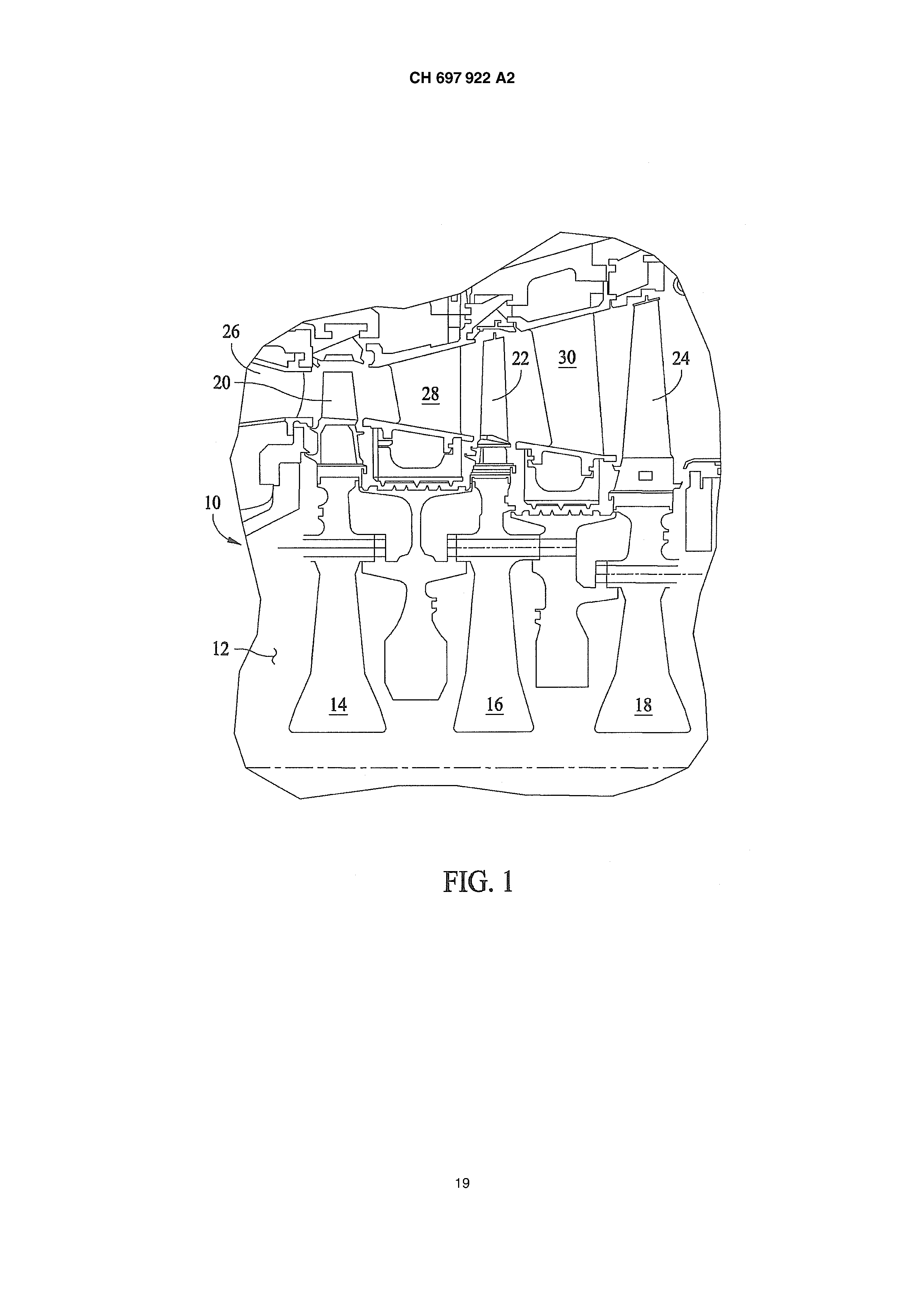
Short description of the designs [00081 Fig. 1 is a schematic cross section representation of an exemplary turbine, the one turbine of the second stage enthält.
Fig. 2 Fig. 3 Fig. 4 Fig.
Fig. 6 Fig. 7 Fig. 8 is a front view of an exemplary turbine blade, those in Fig. 1 turbine shown to be used kann.
a side view is in Fig. 2 Turbinenschaufel.<br shown/>
illustrates a perspective opinion in Fig. and a cartesian coordinate system for the x indicated in table I, Yund Z-Werte.<br illustrates 2 turbine blade shown/>
a chart of cross sections is along the turbine blade in Fig. 4 Linien.<br shown/>
a cross section opinion is in Fig. 2 turbine blade shown along the line 1-1.
a cross section opinion is in Fig. 2 turbine blade shown along the line 2-2.
a cross section opinion is in Fig. 2 turbine blade shown along the line 3-3.
Detailed description of the invention Fig. 1 illustrates a cross section opinion of an exemplary turbine 10. in the remark example contains the turbine 10 a rotor 12, which rotor wheels 14, 16 and 18 first, which exhibits second and/or the third stage, which shovels 20, 22 and/or 24 and stator guide vanes 26, 28 and/or 30 contain. Each row of shovels 20, 22 and/or 24 and stator guide vanes 26, 28 and/or 30 defines a following stage of the turbine 10. in the remark example is the turbine 10 a three speed turbine. Alternatively the turbine can more or less contain 10 as three stages. In an execution form the turbine 10 a gas turbine is manufactured of the type General Electric 6B, by the General Electric company of Schenectady, New York.
Within the second turbine stage the rotor wheel contains 16 shovels 22, which are installed axially opposite the stromaufwärtigen stator guide vanes 30. The shovels 22 are beabstandet around the extent of the Rades 16 of the second stage around. In the remark example the wheel 16 contains ninety-two shovels 22.<br of the second stage/>
Fig. 2 and 3 illustrates a perspective front view and a side view of an exemplary turbine blade 22. In the remark example the shovel 22 contains a wing 40, which extend from a platform 42 outward, and a shank 44, which extend from a opposite side of the platform 42 outward. The radial interior end of the shank 44 extends from a dove tail 46, which serves for it, the shovel 22 to the turbine 16 (in Fig. to couple 1 shown). The dove tail 46 fits as well known into appropriate () dove tail openings not shown, which are defined in the turbine 16. In addition the shovel 22 contains wheel space seals, i.e. angle bars 52, which extend from the shank 44 axially outward. In a remark example the wing 40 insists of a well-known superalloy on nickel basis, like for example AIIoy 738.
Fig. a perspective opinion illustrates 4 in Fig. and a cartesian coordinate system 54 for the x indicated in the following table I, Yund of Z-values illustrates 2 turbine blade shown 22. The cartesian coordinate system 54 has orthogonal to each other standing axles X, Y and Z, whereby the Z-axis, or the datum line runs, essentially perpendicularly to the platform 42 and itself generally in a radial direction by the wing 40 through extended. A first profile cross section 58, a second profile cross section 60, a third profile cross section 62, a fourth profile cross section 64, a fifth profile cross section 66, a sixth profile cross section 68, a seventh profile cross section 70, figure eight profile cross section 72, a ninth profile cross section 74 and a tenth profile cross section 76 of the wing 40 are veranschaulicht.
Fig. 5 is a chart of cross sections of the wing 40 at a first profile cross section 58, a second profile cross section 60, a third profile cross section 62, a fourth profile cross section 64, a fifth profile cross section 66, a sixth profile cross section 68, a seventh profile cross section 70, a respected profile cross section 72, a ninth profile cross section 74 and a tenth profile cross section 76. The y axis extends essentially parallel to an axle center of the turbine, i.e. the axis of rotation. By defining Xund Y-coordinate values at selected positions in the radial direction, i.e. in a Z-direction, the profile of the wing 40 can be determined. By connecting the Xund of Y-values with stepless continuous sheets each profile cross section is fixed in each radial distance Z. The surface profiles at the different surface positions between the radial distances Z can be determined by connecting neighbouring profiles. The Xund Y-coordinates for determining the wing cross section profile in each radial position or wing height Z is represented in the following table I, whereby Z is equal zero at a lower surface 78 of the shovel 22. These table codes are indicated in inches and represent the actual wing profile under environment, Nichtbetriebsoder cold conditions and are valid for an uncoated Flügel.
The wing 40 can at least partly with one (in Fig. 4) coating not shown covered its, whereby the dimensions of the wing 40 can become larger. In a remark example the coating protects the wing of corrosion and/or oxidation. In addition the sign convention used in table I assigns a positive value to the value Z and the coordinates X and Y positive and negative values, like it usually in a cartesian coordinate system used werden.
The values in table 1 are computer-generated and on four places behind the comma proven. In view of the practical manufacturing borders however the actual values, which are usable for training the wing 40, on only three places behind the comma are regarded for determining the profile of the wing 40 as valid. Beyond that there are typical manufacturing tolerances, which are to be considered 40 in the profile of the wing. Accordingly the values specified in table I are valid for the profile of an geometrical-ideal wing. It understands itself around the fact that typical Plusoder minus manufacturing tolerances for the x, Yund of Z-values is valid and that a wing, which essentially exhibits a profile in accordance with these values contains such tolerances. For example a manufacturing tolerance of for instance _+0,010 lies inch within the construction borders for the wing, and preferably a manufacturing tolerance is kept by for instance _+0,008 inches. Accordingly values of X and Y, which are exact on three places behind the comma and a manufacturing tolerance of for instance _+0,010 inches and preferably for instance _+0,008 inches exhibit, are acceptable, around the profile of the wing 40 at each radial position along its entire length too definieren.
The wing 40 lends kinetic energy to the air flow and contributes thereby to a desired current at (not shown) a compressor. The wing 40 turns the fluid flow, slows the relative speed down of the fluid flow within the respective wing reference framework and leads to a rise of the static pressure of the fluid flow. The wing 40 makes possible, together with its reciprocal effect with surrounding wings and edge surfaces, in certain remark examples: a high efficiency of the air flow in the stages, an improved aeromechanics, an even laminar stream from stage to stage, less thermal tensions, an improved interrelation of the stages, in order to transport the air flow effectively from stage to stage, and less mechanical stresses. Usually several series of wing stages, like for example rotor/stator wing, are so aligned that a desired discharge opening inlet pressure relationship is reached. The wings 40 can by means of the dove tail 46 (into the Fig. 2 and 3) coupled shown with the wheels werden.
The adjustment of the wing 40 and each reciprocal effect with surrounding wings support a manufacturing of desirable fluid flow dynamics and a desirable laminar stream. The fluid flow cuts the wing 40 and is strengthened. More exactly said, the fluid dynamics and the laminar stream are strengthened by the wing 40. To that extent an even transition fluid flow is supported to neighbouring and/or stromabwärtigen wings. Beyond that the current of each wing 40 runs downstream toward the neighbouring and/or stromabwärtigen wings and due to the intensified laminar fluid flow by the wing 40 is strengthened. Therefore the adjustment of the wing 40 supports a preventing of fluid flow turbulences in the unit, those the wing 40 umfasst.
In the remark example the configuration of the wing 40 (with or without fluid flow reciprocal effect) can using different construction processes and - muddled to be determined. To such construction processes and - muddled for example the following can belong: computed fluid dynamics (CFD), conventional fluid dynamic analysis, Eulerund Navier Stokes equations, manual positioning, flow test (for example in Windtunneln) and modification of the wings, suburban test, modelling, application of scientific principles to the construction or development of the wings, machines, devices or manufacturing processes, and wing flow tests and - modifizierung.
As addressed above, the configuration of the wing 40 and the reciprocal effect of the wing with surrounding wings and edge surfaces support a high efficiency of the air flow in the stages, an improved aeromechanics, an even laminar stream from stage to stage, less thermal tensions, an improved interrelation of the stages, in order to transport the air flow effectively from stage to stage, and less mechanical stresses as well as further desirable effects compared with similar wings, which have same applications. In the remark example the wing 40 supports the increase of the efficiency of the turbine enterprise compared with turbines, which are equipped with well-known wings. The increased efficiency makes a higher output achievement possible apart from the advantages specified above with fuel consumption reduced at the same time. To that extent also the emissions of the engine become verringert.
As above marked, the wing 40 can be coated in addition, in order to protect it against corrosion and oxidation, after the wing 40 according to the values of table I and within the tolerances described above manufactured wurde.
Therefore additionally an addition indicated in table I can be included to these values, around the coating thicknesses too berücksichtigen. to the manufacturing tolerances for the Xund Y-values in addition
4 point I 2 3 4 6 7 8 9 11 12 13 14 16 17 18 19 21 22 23 24 26 27 28 29 31 32 33 34 TABLE I profile cross section 1 professional {cross section 2 X Y Z X Y I Z -1.2863 -0.5237 4.3045 -0.4461 -0.1553 5.1101 -1.1988 -0.3007 4.3045 -0.8739 0.1801 5.1101 -0.1846 -0.1543 4.3045 -0.6366 -0.2319 5.1101 -0.2999 0.5367 4.3045 -0.1212 -0.1009 5.1101 -0.9855 0.0244 4.3045 -1.0812 -0.1065 5.1101 -0.6967 0.3164 4.3045 -1.2004 -0.3626 5.1101 -0.8939 -0.428 4.3045 -1.1163 -0.5101 5.1101 -1.2639 -0.6589 4.3045 -0.1882 0.5598 5.1101 -1.2719 -0.6549 4.3045 -1.2158 -0.4704 5.1101 -0.4196 0.4898 4.3045 -0.7806 0.2746 5.1101 -1.1477 -0.6294 4.3045 -0.9349 -0.4075 5.1101 -1.2949 -0.597 4.3045 -0.4733 0.4797 5,1101 -0,0521 0.5832 4.3045 -0.7337 0.3155 5.1101 -1.2455 -0.6631 4.3045 -0.3166 -0.1218 5.1101 -1.2657 -0.4528 4.3045 -0.9637 0.0706 5.1101 0.0245 -0.1483 4.3045 0.0048 -0.1069 5.1101 -1.1298 -0.1801 4.3045 -1.1475 -0.2315 5.1101 -0.3224 -0.176 4.3045 -1.1692 -0.5137 5.1101 -0.8772 0.1494 4.3045 -0.0133 0.564 5.1101 -0.7018 -0.312 4.3045 -1.2149 -0.4228 5.1101 -0.5587 -0.2471 4.3045 -1.0615 -0.4867 5.1101 -0.5908 0.3938 4.3045 -0.3051 0.5382 5.1101 -1.0273 -0.5304 4.3045 -1.208 -0.4903 5.1101 -1.2844 -0.6415 4.3045 -1.0355 -0.4718 5.1101 -0.2381 0.5547 4.3045 -0.8245 -0.3362 5.1101 -1.1909 -0.6545 4.3045 -0.5813 0.4235 5.1101 -1.2928 -0.5601 4.3045 -0.5094 -0.1772 5.1101 -1.2233 -0.3504 4.3045 -0.8254 0.2315 5.1101 -0.115 -0.1487 4.3045 -0.0694 0.5664 5.1101 -1.0363 -0.0419 4.3045 -0.1842 -0.1036 5.1101 -0.4813 -0.219 4.3045 -1.0443 -0.046 5.1101 -0.7595 0.2636 4.3045 -1.1891 -0.3291 5,1101 -0,8316 -0.3865 4.3045 -1.1339 -0.5141 5.1101 -0.4783 0.4608 4.3045 -0.1289 0.565 5.1101 -1.123 -0.6106 4.3045 -1.2173 -0.4598 5.1101 professional {cross section 3 X Y I Z 0.0433 -0.0905 5.9156 -1.115 -0.15 5.9156 -1.1211 -0.3644 5, ç156 -1.1587 -0.2834 5.9156 -0.5176 -0.1255 5.9156 -1.0141 -0.3555 5.9156 -0.2816 0.5688 5.9156 -0.771 -0.2363 5.9156 -0.5587 0.4798 5.9156 -0.8064 0.2978 5.9156 -0.1371 -0.0659 5.9156 -1.0184 0.0305 5.9156 -1.1401 -0.2134 5.9156 -1.0873 -0.3701 5.9156 -0.11 0.5753 5.9156 -1.1605 -0.3137 5.9156 -0.9348 -0.3211 5.9156 -0.3938 0.5452 5.9156 -0.6463 -0.1763 5.9156 -0.6617 0.4179 5.9156 -0.5825 -0.1494 5.9156 -0.3024 -0.0742 5.9156 -0.8986 0.197 5.9156 -0.0163 -0.0784 5.9156 -1.0856 -0.0883 5.9156 -1.1364 -0.3565 5.9156 0,0615I 0.5472 5.9156 -1.15511-0.2646 5.9156 -1.0416 -0.3639 5.9156 -0.2245 0.5748 5.9156 -0.8323 -0.2683 5,9156 -0,5044 0.5057 5.9156 -0.4648 -0.1089 5.9156 -0.7563 0.3441 5.9156 0.0036 0.5606 5.9156 profile cross section 1 point X Y Z 36 -1.2933 -0.6154 4.3045 37 -0.1139 0.578 4.3045 38 -1.2269 -0.6637 4.3045 39 -1.2771 -0.488 4.3045 -1.1724 -0.2519 4.3045 41 -0.2538 -0! 634 4.3045 42 -0.9322 0.0886 4.3045 43 -0.6345 -0.2793 4.3045 44 -0.6445 0.3563 4.3045 -0.9543 -0.4721 4.3045 46 -1.2788 -0.6489 4.3045 47 -0.3604 0.515 4.3045 48 - I, 1741 -0.6461 4.3045 49 - I, 2946 -0.5785 4.3045 0.0099 0.5841 4.3045 51 -1.2457 -0.4011 4.3045 52 -0.0453 -0.1467 4.3045 53 -1.0844 -0.11] 4.3045 54 -0.4024 -0.1953 4.3045 -1.099 -0.5906 4.3045 56 -0, õ197 0.2078 4.3045 57 -0.7676 -0.3478 4.3045 58 -0.5353 0.4287 4.3045 59 - I, 2902 -0.6289 4.3045 -0.1753 0.5686 4.3045 61 - I, 2086 -0.6607 4.3045 62 0.1332 0.5721 4.3045 63 1.3681 -0.8619 4.3045 64 0.1593 -0.1619 4.3045 0.4104 0.4721 4.3045 66 1.3064 -0.9038 4.3045 67 0.6542 0.2873 4.3045 68 1.2324 -0.8528 4,3045 69 0.9218 -0.032 4.3045 0.9982 -0.6024 4.3045 71 1.2437 -0.5656 4.3045 72 0.6659 -0.3466 4.3045 73 1.3692 -0.8165 4.3045 74 0.3510 -0.2061 4.3045 0.2501 0.5429 4.3045 76 1.3496 -0.8873 4.3045 77 0.5118 0.407 4.3045 78 1.2767 -0.8963 4.3045 professional [cross section 2 profile cross section 3 X! Y Z X Y Z -0,9848I -0.4402 5.1101 -0.1924 -0.0654 5.9156 -0.4184 0.5025 5.1101 -0.9809 0.0877 5.9156 -0.7004 -0.2644 5.1101 -1.1282 -0.1814 5.9156 -0.6849 0.3542 5.1101 -1.1046 -0.3688 5.9156 -0.3818 -0.1308 5.1101 -0.053 0.5698 5.9156 -0.92 0.1264 5.1101 -1.1606 -0.3024 5.9156 -0.0581 -0.102 5.1101 -0.9872 -0.3449 5.9156 -1.1157 -0.1683 5.1101 -0.3381 0.5589 5.9156 -1.1859 -0.5078 5.1101 -0.4112 -0.0947 5.9156 0.0425 0.5581 5.1101 -0.709 -0.2054 5.9156 -1.2098 -0.3967 5.1101 -0.6111 0.4505 5.9156 -1.0883 -0.4999 5.1101 -0.3571 -0.0831 5.9156 -0.247 0.5509 5.1101 -1.1554 -0.3358 5.9156 -1.2129 -0.4808 5.1101 -0.8538 0.2486 5.9156 -0.885 -0.3746 5.1101 -0.0765 -0.0702 5.9156 -0.5269 0.4538 5.1101 -1.0534 -0.0281 5.9156 -0.5715 -0.2021 5.1101 -1.1495 -0.3451 5.9156 -0.2507 -0.1106 5.1101 -1.1504 -0.2461 5.9156 - I, 0051 0.0131 5.1101 -1,0699 -0,3691 5.9156 -1.1762 -0.2961 5.1101 -0.1673 0.577 5.9156 -1.1516 -0.5157 5.1101 -1.1589 -0.325 5.9156 -1.2174 -0.4492 5.1101 -0.4485 0.5278 5.9156 -0.3623 0.5221 5.1101 -0.71 0.3823 5.9156 -1.2012 -0.498 5.1101 -0.8833 -0.2952 5.9156 -0.763 -0.2993 5.1101 -0.2475 -0.0683 5.9156 -0.634 0.3902 5.1101 -0.941 0.1433 5.9156 1.2154 -0.9757 5.1101 1.2034 -1.0493 5.9156 0.6142 0.2446 5.1101 1.209 -1.0301 5.9156 1.2621 -0.9892 5.1101 0.3262 -0.2069 5.9156 0.3675 0.4441 5.1101 0.5892 -0.4104 5.9156 0.1909 -0.145 5.1101 0.9255 -0.3487 5.9156 1.291 -0.9507 5.1101 0.9136 -0.7676 5.9156 0.0977 0.5486 5.1101 1.1262 -1.0195 5.9156 0.4816 -0.2792 5.1101 1.1804 -0.9489 5.9156 1.2605 -0.8676 5.1101 1.1396 -1.0351 5.9156 0.8101 -0.5358 5.1101 0.6386 0.1329 5.9156 1.0211 -0.3656 5.1101 0.4757 0.3121 5.9156 1.1577 -0.9065 5.1101 1.1793 -1.0629 5.9156 0.7601 0.0683 5.1101 0,7188 0,0211 5.9156 1.2322 -0.9882 5.1101 0.1595 -0.1259 5.9156 0.5125 0.3407 5.1101 0.174 0.5089 5.9156 1.2788 -0.9786 5.1101 1.0665 -0.6643 5.9156 0.2613 0.4976 5.1101 1.1613 -1.0577 5.9156 profile cross section 1 profile cross section 2 point X Y Z X Y Z 79 0.7403 0.1979 4.3045 0.3111 -0.1895 5.1101 1.1917 -0.8056 4.3045 1.2876 -0.9286 5.1101 81 1.059 -0.2403 4.3045 0.6076 -0.3652 5.1101 82 0.8574 -0.4793 4.3045 1.1785 -0.6871 5.1101 83 1.3298 -0.7316 4.3045 0.9767 -0.7022 5.1101 84 0.5428 -0.2807 4.3045 0.9057 -0.1565 5.1101 0.0718 0.5804 4.3045 1.2082 -0.9677 5.1101 86 1.3725 -0.8458 4.3045 0.0673 -0.1156 5.1101 87 0.2241 -0.1735 4.3045 0.5613 0.1929 5.1101 88 0.2882 -0.1883 4,3045! , 2523 -0.9912 5.1101 89 0.3585 0.4992 4.3045 0.129 -0.1282 5.1101 90 1.3218 -0.9018 4.3045 1.2891 -0.9616 5.1101 91 0.6086 0.3293 4.3045 0.1523 0.5356 5.1101 92 1.253 -0.8751 4.3045 0.4262 -0.2467 5.1101 93 0.8641 0.0459 4.3045 1.279 -0.9076 5.1101 94 1.0648 -0.6681 4.3045 0.7445 -0.4766 5.1101 95 1.1844 -0.4559 4.3045 1.0751 -0.472 5.1101 96 0.7252 -0.3835 4.3045 1.1073 -0.8474 5.1101 97 1.3635 -0.802 4.3045 0.8111 -0.005 5.1101 98 0.4141 -0.2269 4.3045 0.4178 0.4124 5.1101 99 0.1939 0.5592 4.3045 1.2233 -0.9829 5.1101 100 1.3502 -0.8757 4.3045 0.5647 0.294 5.1101 101 0.0941 -0.1536 4.3045 1.2712 -0.9848 5.1101 102 0.4605 0.442 4.3045 0.3152 0.4726 5.1101 103 1.291 -0.902 4.3045 0.2516 -0.1655 5.1101 104 0.698 0.2434 4.3045 1.2903 -0.9396 5.1101 105 1.2122 -0.8291 4,3045 0,5356 -0.314 5.1101 106 0.9921 -0.135 4.3045 1.2281 -0.7958 5.1101 107 0.9291 -0.5393 4.3045 0.8948 -0.6176 5.1101 108 1.3015 -0.6761 4.3045 0.9648 -0.2603 5.1101 109 0.6051 -0.3122 4.3045 1.2012 -0.9594 5.1101 110 1.3728 -0.8315 4.3045 0.7061 0.1392 5.1101 111 0.305 0.5229 4.3045 1.2424 -0.991 5.1101 112 1.3366 -0.8961 4.3045 0.4661 0.3779 5.1101 113 0.5612 0.3693 4.3045 1.2849 -0.9706 5.1101 114 1.2642 -0.8871 4.3045 0.2058 0.519 5.1101 115 1.3571 -0.7877 4.3045 0.3693 -0.2167 5.1101 116 0.8038 0.1237 4.3045 1.2837 -0.918 5.1101 117 1.1291 -0.736 4.3045 0.6771 -0.4195 5.1101 118 1.123 -0.3473 4.3045 1.1275 -0.5792 5.1101 119 0.7828 -0.423 4.3045 1.0561 -0.789 5.1101 120 0.4791 -0.2523 4.3045 0.8595 -0.0801 5.1101 profile cross section 3 X Y Z 0.2281 0.4844 5.9156 0.7087 -0.5318 5.9156 0,9744 -0,4531 5.9156 1.0832 -0.9694 5.9156 1.1528 -0.8781 5.9156 1.1531 -1.0511 5.9156 0.5609 I 0.2258 5.9155 0.7604 -0.0438 5.9155 1.197 -1.0564 5.9156 0.333 0.4242 5.9156 1.0212 -0,5584I 5.9156 0.2815 0.4559 5.9156 0.8404 -0.6808 5.9156 1.1329 -1.0272 5.9156 0.6749 0.0844 5.9156 0.8 -0.1101 5.9156 1.17 -1.0617 5.9156 0.2722 -0.1766 5.9156 0.102 -0.1064 5.9156 1.2076 -1.0406 5.9156 0.3786 -0.24 5.9156 1.1957 -0.9884 5.9156 1.2034 -1.0091 5.9156 0.65 -0.4701 5.9156 0.9864 -0.8547 5.9156 0.5261 -0.3531 5.9156 0.8378 -0.1774 5.9156 1.1461 -1.0432 5.9156 0.6006 0.1801 5.9156 1.1887 -1.0611 5.9156 1.1104 -0.7708 5.9156 0.3826 0.3895 5.9156 0.2167 -0.1495 5.9156 0.1183 0.5299 5.9156 0.4786 -0.3135 5.9156 1.2071 -1.0195 5.9156 0.4294 -0.2757 5.9156 0.7659 -0.595 5.9156 0.8739 -0.2456 5.9156 1.1995 -0.9987 5.9156 0.5193 0.2699 5.9156 0.4302 0.352 5,9156 7 hole 1 -0.663 -0.0626 4.3045 -0.2702 I 0.1279 5.1101 -0.5863 0.0714 5.9156 hole 2 -0.2928 0.102 4.3045 -0.6246 I 0.0044 5.1101 -0.2477 0.1538 5.9156 hole 3 0.4613 0.0371 4.3045 0.8424 -0.3783 5.1101 0.4303 -0.0478 5.9156 hole 4 0.8746 -0.3089 4.3045 0.4458 -0.0054 5 1101 0.8101 -0.4478 5.9156 hole 5 0.0875 0.1167 4.3045 0.0965 0.0998 5.1101 0.1055 0.0828 5.9156 point 1 2 3 4 6 7 8 9 11 12 13 14 16 17 18 19 21 22 23 24 26 27 28 29 31 32 33 34 36 profile cross section 4 X Y Z X Y I Z X Y Z -0.9981 -0.2284 6.7212 -0.6613 -0.04 7.5267 -1,0043 0.1373 8.3323 -1.1125 -0.1884 6.7212 -0.6656 0.4981 7.5267 -1.0263 0.0535 8.3323 -0,7868 -0,1582 6.7212 -0.8611 0.3293 7.5267 -0.6842 0.0523 8.3323 -0.7015 0.4419 6.7212 -1.0014 0.1286 7.5267 -0.6058 0.5504 8.3323 -0.9052 0.2461 6.7212 - I, 0396 -0, I022 7.5267 -0.798 0.4131 8.3323 -1.0705 -0.0172 6.7212 - I, 0629 -0.0184 I 7.5267 -0.8663 0.3425 8.3323 -1.0596 -0.228 6.7212 -0.962 -0.1145 7.5267 -0.951 0.2319 8.3323 -1.1146 -0.1586 6.7212 -1.0635 -0.0781 7.5267 -1.0123 0.0196 8.3323 -1.1033 -0.2055 6.7212 -1.0528 -0.0933 7.5267 -1.0205 0.0935 8.3323 -0.6617 -0.1106 6.7212 -0.8337 -0.086 7.5267 -0.9584 0.0019 8.3323 -0.5739 0.5197 6.7212 -0.5213 0.5678 7.5267 -1.0226 0.0351 8.3323 -0.7891 0.37 6.7212 -0.5361 o0,018 7.5267 -0.8292 0.0219 8.3323 -0.9728 0.1551 6.7212 -0.7526 0.4354 7.5267 -0.5752 0.065 8.3323 profile cross section 5 profile cross section 6 - I, 0954 -0.0785 6.7212 -0.9243 0.2501 7,5267 -0,683 0.5052 8.3323 -0.5339 -0.0713 6.7212 - I, 0369 0.057 7.5267 -0.9908 0.1652 8.3323 -1.026 -0.2307 6.7212 -1.0101 -0.1126 7.5267 -0.9923 0.0079 8.3323 -1.1144 -0.1785 6.7212 -1.0675 -0.0499 7.5267 -1.0261 0.0629 8.3323 -0.9439 -0.2157 6.7212 -0.9305 -0.1102 7.5267 -0.9194 0.004 8.3323 -0.8387 -0.1788 6.7212 -0.7191 -0.0539 7.5267 -0.7411 0.0416 8.3323 -0.6605 0.4702 6.7212 -0.6192 0.5248 7.5267 -0.5651 0.5693 8.3323 -0.8685 0.2892 6.7212 -0.8658 -0.0949 7.5267 -0.7614 0.4459 8.3323 -1.0411 0.042 6.7212 -0.8268 0.3666 7.5267 -0.9245 0.27 8.3323 -1.0755 -0.2233 6.7212 -0.9774 0.1702 7.5267 -0.9813 0.0047 8.3323 -1.1111 -0.1341 6.7212 -1.0589 -0.0029 7.5267 -1.0158 0.1084 8.3323 -0.9708 -0.223 6.7212 -0.978 -0.1152 7.5267 -0.9699 0.0028 8.3323 -1.1089 -0.1976 6.7212 -1.0663 -0.0689 7.5267 -1.0253 0.0442 8.3323 -0.7244 -0.1338 6.7212 -0.5989 -0.0275 7,5267 -0,8608 0.0148 8.3323 -0.5286 0.5404 6.7212 -0.7102 0.4682 7.5267 -0.6268 0.0603 8.3323 -0.7463 0.4072 6.7212 -0.898 -0.1032 7.5267 -0.6451 0.5289 8.3323 - O, ç4 0.2013 6.7212 -0.8936 0.2904 7.5267 -0.833 0.3786 8.3323 -1.0836 -0.0476 6.7212 -1.0235 0.086 7.5267 -0.9757 0.1924 8.3323 -1.0429 -0.2303 6.7212 -1.0659 -0.034 7.5267 -1.0028 0.0128 8.3323 -1.115 -0.1685 6.7212 -0.9462 -0.1128 7.5267 -1.024 0.0784 8.3323 -0.8909 -0.1984 6.7212 -1.059 -0.0865 7.5267 -0.9468 0.0019 8.3323 -0.5982 -0.0896 6.7212 -0.7765 -0.0096 7.5267 -1.0184 I 0.0267 8.3323 -0.6179 0.4962 6.7212 -0.571 0.5481 7.5267 -0,8925! 0,0082 8.3323 profile cross section 4 profile cross section 5 profile cross section 6 point X Y Z X Y Z X Y Z 37 -0.8298 0.3306 6.7212 -1.0253 -0.1085 7.5267 -0.7976 0.0292 8.3323 38 -1.0085 0.0994 6.7212 -0.7906 0.4021 7.5267 -0.7231 0.4767 8.3323 39 -1.0903 -0.216 6.7212 -0.9517 0.2107 7.5267 -0.8962 0.3069 8.3323 -1.1053 -0.11 6.7212 -1.0488 0.0274 7.5267 0.0185 0.5357 8.3323 41 -0.2405 0.6006 6.7212 -0.9942 -0.1147 7.5267 0.0299 -0.0727 8.3323 42 -0.482 0.5583 6.7212 -1.0675 -0.0594 7.5267 -0.1377 0.0051 8.3323 43 -0.4686 -0.0563 6.7212 -0.3458 -0.0095 7.5267 -0.1876 0.6104 8.3323 44 0.0509 0.548 6.7212 -0.0338 -0.0688 7.5267 -0.3925 0.617 8.3323 -0.0929 0.5879 6.7212 -0.011 0.5591 7.5267 -0.4718 0.0677 8.3323 46 -0.3379 0.5933 6.7212 -0.3211 0.6074 7.5267 -0.0624 0.5735 8.3323 47 -0.1578 -0.0417 6,7212 -0,2705 0.6084 7.5267 -0.2691 0.621 8.3323 48 -0.1916 0.5996 6.7212 -0.2191 -0.0221 7.5267 -0.4806 0.5992 8.3323 49 -0.4345 0.5732 6.7212 0.0819 -0.1171 7.5267 -0.3175 0.053 8.3323 -0.2825 -0.036 6.7212 -0.114 0.5897 7.5267 -0.0237 -0.044 8.3323 51 -0.22 -0.0368 6.7212 -0.3714 0.6029 7.5267 0.0573 0.5135 8.3323 52 0.0738 -0.0985 6.7212 -0.4094 -0.0088 7.5267 -0.1475 0.6013 8.3323 53 -0.0442 0.5774 6.7212 -0.0947 -0.0495 7.5267 -0.3515 0.621 8.3323 54 -0.2893 0.5985 6.7212 0.0389 0.5389 7.5267 -0.1967 0.0246 8.3323 0.0181 -0.0791 6.7212 -0.2201 0.6059 7.5267 -0.0214 0.5558 8.3323 56 -0.407 -0.0459 6.7212 0.0874 0.5155 7.5267 -0.2282 0.617 8.3323 57 -0.0961 -0.0508 6.7/12 -0.4703 0.5836 7.5267 -0.4369 0.6096 8.3323 58 -0.1421 0.5953 6.7212 -0.2823 -0.0139 7.5267 -0.3687 0.0605 8.3323 59 -0.3861 0.585 6.7212 0.0247 -0,0913 7,5267 -0.1045 0.5888 8.3323 -0.3449 -0.039 6.7212 -0.062 0.5761 7.5267 -0.3103 0.6223 8.3323 61 0.0038 0.5641 6.7212 -0.4729 -0.0117 7.5267 -0.5234 0.5857 8.3323 62 - Õ, 0386 -0.0632 6.7212 -0.1565 -0.0339 7.5267 -0.4201 0.0654 8.3323 63 0.5121 -0.4022 6.7212 -0.1668 0.5997 7.5267 -0.5235 0.0675 8.3323 64 0.2335 -0.1761 6.7212 -0.4212 0.595 7.5207 -0.08 -0.0178 8.3323 0.3917 0.332 6.7212 0.4302 0.2293 7.5267 -0.2567 0.0406 8.3323 66 0.3803 -0.2798 6.7212 0.2284 0.4257 7.5267 0.2785 -0.2628 8.3323 67 0.4698 -0.3597 6.7212 0.239 -0.2112 7.5267 0.5138 -0.5433 8.3323 68 0.1812 -0.1469 6.7212 0.4538 -0.4053 7.5267 0.5465 -0.0571 8.3323 69 0.5219 0.1929 6.7212 0.5477 0.0694 7.5267 0.3347 0.2649 8.3323 0.3023 0.4075 6.7212 0.3546 0.3135 7.5267 0.1311 0.4634 8.3323 71 0.1043 0.5261 6.7212 0.1362 0,4883 7,5267 0.1322 -0.1386 8.3323 72 0.1282 -0.1211 6.7212 0.3296 -0.2834 7.5267 0.3684 -0.3588 8.3323 73 0.4336 0.2912 6.7212 0.5435 -0.5097 7.5267 0.4555 0.0973 8.3323 74 0.2063 0.4727 6.7212 0.4656 0.185 7.5267 0.2527 0.3563 8.3323 0.333 -0.2429 6.7212 0.2719 0.3908 7.5267 0.2307 -0.2179 8.3323 76 0.1561 0.5009 6.7212 0.4138 -0.3632 7.5267 0.4518 -0.4607 8.3323 77 0.568 -0.4627 6.7212 0.5858 0.0096 7.5267 0.5884 -0.1363 8.3323 78 0.5675 0.1353 6.7212 0.3932 0.2722 7.5267 0.3772 0.2107 8.3323 79 0.3479 0.3709 6.7212 0.1832 0.4583 7.5267 0.1734 0.4297 I 8.3323 profile cross section 4 profile cross section 5 profile cross section 6 point X Y Z X Y Z X Y Z 0.4259 -0.3189 6.7212 0.2852 -0.2463 7.5267 0.0819 -0, I043 8.3323 81 0.2841 -0.2082 6.7212 0.4923 -0.4486 7.5267 0.3244 -0,3099 8,3323 82 0.4739 0.2485 6.7212 0.5077 0.128 7.5267 0.5738 -0.6275 8.3323 83 0.2548 0.4417 6.7212 0.3141 0.3531 7.5267 0.5023 0.0209 8.3323 84 1.0795 -0.9325 6.7212 0.1374 -0.1463 7.5267 0.2898 0.317 8.3323 0.7891 -0.7435 6.7212 0.3725 -0.3225 7.5267 0.0948 0.4893 8.3323 86 0.8312 -0.3115 6.7212 0.1911 -0.1786 7.5267 0.1806 -0.1754 8.3323 87 1.0547 -1.0798 6.7212 0.5929 -0.5723 7.5267 0.4108 -0.4092 8.3323 88 0.6106 0.0759 6.7212 0.957 -1.0719 7.5267 0.4173 0.1548 8.3323 89 1.0965 -1.1181 6.7212 0.6219 -0.0513 7.5267 0.2139 0.394 8.3323 90 1.128 -1.1008 6.7212 1.0589 -1.1462 7.5267 0.9995 -1.1718 8.3323 çl 1.1193 -1.0513 6.7212 1.0188 -1.1509 7.5267 0.9609 -1.0505 8.3323 92 0.988 -0.681 6.7212 1.0584 -1.1001 7.5267 0.738 -0.4617 8.3323 93 0.740610.1453 6.7212 0.9722 -0.8543 7.5267 0.8329 -1.0105 8.3323 94 1,0714 -1.0984 6.7212 0.6882 -0.7001 7.5267 0.9435 -1.182 8.3323 95 1.1101 -1.1178 6.7212 0.7458 -0.2913 7.5267 0.9818 -1.194 8.3323 96 1.1292 -1.0815 6.7212 0.9995 -1.129 7.5267 0.9922 -1.1364 8.3323 97 1.1032 -1.0022 6.7212 1.0653 -1.1297 7.5267 0.8756 -0.8134 8.3323 98 0.7235 -0.6552 0.7212 0.8819 -0.0122 7.5267 0.6327 -0.7126 8.3323 99 0.8868 -0.4333 6.7212 0.874 -0.959 7.5267 0.6664 -0.2975 8.3323 100 1.0129 -1.0317 6.7212 0.6656 -0.1301 7.5267 0.8861 -1.0922 8.3323 101 1.0903 -1.1154 6.7212 1.0115 -1.1443 7.5267 0.9996 -1.1622 8.3323 102 0.6515 0.0151 6.7212 1.0525 -1.1524 7.5267 0.9566 -1.1934 8.3323 103 1.1233 -1.1089 6.7212 0.6409 -0.6359 7.5267 0.9961 -1.1809 8.3323 104 0.6216 -0.5254 6.7212 1.0618 -1.1099 7.5267 0.9742 -1.0874 8.3323 105 1.1227 -1.0613 6.7212 1.0356 -1.1575 7.5267 0.7855 -0.5783 8.3323 106 1,0348 -0.8064 6.7212 1.0152 -0.9763 7.5267 0.8061 -0.9698 8.3323 107 0.9661 -0.9761 6.7212 0.783 -0.3733 7.5267 0.9387 -1.1746 8.3323 108 0.8544 -0.8319 6.7212 0.9938 -1.1212 7.5267 0.9734 -1.1964 8.3323 109 0.790110.2278 6.7212 1.0271 -1.1557 7.5267 0.9964 -1.1492 8.3323 110 1.0629 -1.0892 6.7212 1.0633 -1.1384 7.5267 0.9189 -0.9315 8.3323 111 1.1033 -1.1189 6.7212 0.8338 -0.4922 7.5267 0.7028 -0.3793 8.3323 112 1.1301 -1.0918 6.7212 1.0551 -1.0904 7.5267 0.8596 -1.0513 8.3323 113 1.1161 -1.0413 6.7212 0.9278 -0.733 7.5267 0.99 -1.1886 8.3323 114 0.9209 -0.9194 6.7212 1.0518 - I, 0809 7.5267 0.9878 -1.124 8.3323 115 0.6733 -0.5897 6.7212 0.7812 -0.8295 7.5267 0.8313 -0.6956 8.3323 116 0.9389 -0.5565 6.7212 0.7067 -0.2102 7.5267 0.9494 -1.1884 8.3323 117 0.7006 -0.0642 6.7212 1.0053 -1.1368 7.5267 0.7199 -0,8408 8,3323 118 1.1166 -1.1149 6.7212 1.0445 -1.1563 7.5267 0.6283 -0.2165 8.3323 119 1.0804 -1.1074 6.7212 1.0645 -1.1198 7.5267 0.9125 -1.1333 8.3323 120 1,1263 -1.0713 6.7212 1.0386 -1.0435 7.5267 0.9648 -1.1962 8.3323 hole 1 -0.5479 0.1383 6.7212 -0.5096 0.2053 7.5267 hole 2 -0.2251 0.1797 6.7212 -0.2026 0.2056 7.5267 hole 3 0.4148 -0.0903 6.7212 0.3993 -0.1327 7.5267 hole 4 0.1145 0.0659 6.7212 0.1236 0.0489 I 7.5267 hole 5 0.7778 -0.5172 6.7212 0.7455 -0.5867 I 7.5267 -0.18 0.2314 8.3323 -0.4713 0.2723 8.3323 0.3838 -0.1752 8.3323 0.1326 0.0319 8.3323 0.7132 -0.6561 8.3323 point 1 2 3 4 6 7 8 9 11 12 13 14 16 17 18 19 21 22 23 24 26 27 28 29 31 32 33 34 36 profile cross section 7 X Y Z X Y -0.9264 0.1336 9.1378 -0.8565 0.4588 -0.9854 0.1605 9.1378 -0.5619 0.6317 -0.7311 0.1622 9.1378 -0.675 0.5858 -0.6348 0.5555 9.1378 -0.7539 0.2871 -0.8293 0.4179 9.1378 -0.9004 0.2828 -0.9569 0.267 9.1378 -0.946 0.3286 -0.9604 0.1375 9.1378 -0.9427 0.3014 -0.8709 0.1391 9.1378 -0.9159 0.3908 -0.6287 0.1735 9.1378 -0.7871 0.5171 profile cross section 8 profile cross section 9 Z X Y Z 9.9434 -0.6547 0.4314 10.7489 9.9434 -0.5888 0.7092 10.7489 9.9434 -0.8107 0.4492 10.7489 9.9434 -0.7585 I 0.6433 10.7489 9.9434 -0.8868 0.4674 10.7489 9.9434 -0.8708 0.5568 10.7489 9.9434 -0.9023 0.5093 10.7489 9.9434 -0.8995 0.4782 10.7489 9.9434 -0.9035 0.4856 10.7489 -0.5199 0.6052 9.1378 -0.6004 0.6185 9.9434 -0.9813 0.1523 -0.7175 0.5058 -0.8933 0.3526 -0.9776 0.2261 -0.9434 0.1343 -0.9877 0.1694 -0.782 0.1542 -0.5256 0.1759 -0.5914 0.5768 -0,7948 0,4479 -0.9404 0.2927 -0.9683 0.1409 -0.9866 0.1969 -0.9093 0.1345 -0.68 0.1688 -0.6768 0.5317 -0.8622 0.3861 -0.9714 0.2401 -0.661 0.6882 10.7489 9.1378 -0.5956 0.289 9.9434 -0.855 0.4565 10.7489 9.1378 -0.8441 0.2822 9.9434 -0.8136 0.6075 10.7489 9.1378 -0.9226 0.2871 9.9434 -0.8913 0.5303 10.7489 9.1378 -0.9402 0.3477 9.9434 -0.9051 0.4937 10.7489 9.1378 -0.6409 0.2902 9.9434 -0.6105 0.4245 10.7489 9.1378 -0.8777 0.4373 9.9434 -0.5502 0.7167 10.7489 9.1378 -0.711 0.5605 9.9434 -0.7884 0.4466 10.7489 9.1378 -0.6861 0.2898 9.9434 -0.7269 0.6602 10.7489 9.1378 -0.8892 0.282 9.9434 -0.8765 0.4628 10.7489 9.1378 -0.9471 0.3187 9.9434 -0.8591 0.5689 10.7489 9.1378 -0.9372 0.295 9.9434 -0.8991 0.5165 10.7489 9.1378 -0.9267 0.3742 9.9434 -0.5665 0.4161 10.7489 9.1378 -0.8228 0.489 9.9434 -0.627 0.6993 10.7489 9.1378 -0.6381 0.6031 9.9434 -0.8329 0.4524 10.7489 9.1378 -0,5504 0,2861 9.9434 -0.789 0.6246 10.7489 9.1378 -0.8215 0.2832 9.9434 -0.8816 0.544 10.7489 9.1378 -0.9116 0.2844 9.9434 -0.9044 0.5018 10.7489 9.1378 -0.9435 0.3382 9.9434 -0.8938 0.4721 10.7489 -0.988 0.1878 9.1378 -0.946 0.3088 9.9434 -0.7215 0.4396 10.7489 -0.952 0.1355 9.1378 -0.8976 0.4147 9.9434 -0.6943 0.6751 10.7489 -0.9884 0.1786 9.1378 -0.7498 0.543 9.9434 -0.8658 0.4592 10.7489 -0.8328 0.1454 9.1378 -0.8666 0.2817 9.9434 -0.837 0.589 10.7489 -0.5771 0.1759 9.1378 -0.9304 0.2903 I 9.9434 -0.8954 0.5235 10.7489 -0.556 0.5919 9.1378 -0.9361 0.3569 I 9.9434 0.0006 0.5009 10.7489 -0.7569 0.4778 9.1378 -0.0697 0.0944 9.9434 -0.2626 0.2926 10.7489 -0.9224 0.3173 9.1378 -0.2807] 0.2208 9.9434 -0.1441 0.6273 10.7489 11 point 37 38 39 41 42 43 44 46 47 48 49 51 52 53 54 56 57 58 59 61 62 63 64 66 67 68 69 71 72 73 74 76 77 78 79 profile cross section 7 profile cross section 8 X Y Z X I Y Z -0.9755 0.1458 9.1378 -0.5054 0.2812 9.9434 -0.9827 0.2117 9.1378 -0.4838 0.6511 9.9434 -0.2522 0.6356 9.1378 -0.2899 0.6556 9.9434 -0.4457 0.6258 9.1378 -0.1117 0.5972 9.9434 -0.4741 0.1733 9.1378 0.0428 -0.0072 9.9434 ù0,2295 0.1207 9.1378 0.0461 0.4817 9.9434 -0.0071 0.0027 9.1378 -0.1521 0.1529 9.9434 0.0503 0.5047 9.1378 -0.3703 0.2529 9.9434 -0.1345 0.6081 9.1378 -0.4048 0.6607 9.9434 -0.331 0.6394 9.1378 -0.2163 0.6395 9.9434 -0.3721 0.1602 9.1378 -0.0458 0.5572 9.9434 -0.1386 0.0815 9.1378 -0.0307 0.0622 9.9434 0.0783 -0.0645 9.1378 -0.2375 0.201 9.9434 -0.022 0.5546 9.1378 -0.4606 0.2743 9.9434 -0.2123 0.6294 9.1378 -0.5228 0.6427 9.9434 -0,4078 0,6328 9.1378 -0.3274 0.6599 9.9434 -0.2763 0.1366 9.137810.1456 0.6136 9.9434 -0.0523 0.033 9.1378 0.0167 0.5085% 9434 0.0842 0.4767 9.1378 -0.1102 O, 1247 9.9434 -0.097 0.5933 9.1378 -0.4164 0.2651 9.9434 -0.2924 0.6389 9.1378 -0.2528 0.6488 9.9434 -0.4831 0.6166 9.1378 -0.325 0.2382 9.9434 -0.4229 0.1682 9.1378 -0.4444 0.6571 9.9434 -0.1835 0.1023 9.1378 -0.0789 0.5787 9.9434 0.0364 -0.0298 9.1378 0.0068 0.0283 9.9434 0.0149 0.5307 9.1378 -0.1955 0.1788 9.9434 -0.173 0.6202 9.1378 -0.3651 0.6615 9.9434 -0.3696 0.6374 9.1378 -0.1806 0.6277 9.9434 -0.3239 0.1498 9.1378 -0.0139 0.5337 9.9434 -0.0948 0.0584 9.1378 0.1338 0.386 9.9434 -0.0605 0.576 9.1378 0.4935 -0.2518 9.9434 0.3243 -0.3366 9.1378 0.4529 -0.5959 9.9434 0.5626 -0.6994 9.1378 0.2308 -0.2382 9.9434 0.5815 -0.2938 9.1378 0.25 0.2203 9.9434 0.3869 0.0883 9.1378 0.5896 -0.4744 9,9434 0,2168 0.3377 9.1378 0.4428 -0.1417 9.9434 0.1167 0.447 9.1378 0.3293 -0.3873 9.9434 0.202 -0.1863 9.1378 0.1599 -0.1423 9.9434 0.3991 -0.4422 9.1378 0.1011 0.4245 9.9434 0.4931 -0.1086 9.1378 0.3898 -0.0326 9.9434 0.3233 0.191 9.1378 0.5119 -0.7018 9.9434 0.1478 0.416 9.1378 0.1945 0.305 9.9434 0.2851 -0.2853 9.1378 0.2645 -0.2873 9.9434 professional [cross section 9 X Y I Z -0.0741 0,1363I 10.7489 -0.3066 0.7033 10.7489 -0.4718 0.7241 10.7489 -0.3956 0.3629 10.7489 -0.0543 0.5561 10.7489 -0.1813 0.2339 10.7489 -0.2073 0.6644 10.7489 -0.4798 0.3936 10.7489 -0.0102 0.0662 10.7489 -0.3719 0.7176 10.7489 0.0264 0.4717 10.7489 -0.3055 0.3185 10.7489 -0.1142 0.6061 10.7489 -0.1079 0.1696 10.7489 -0.2747 0.6932 10.7489 0.0616 -0.0235 10.7489 -0.4384 0.7239 10.7489 -0.4373 0.3793 10.7489 -0.0263 0.529 10.7489 -0.2212 0.2643 10.7489 -0.1752 0.6468 10.7489 -0,0416 0,1017 10.7489 -0.3391 0.7114 10.7489 -0.5111 0.7217 10.7489 0.0512 0.4417 10.7489 -0.3499 0.342 10.7489 -0.0836 0.5818 10.7489 -0.1428 0.2016 10,7489: 0,2405 0.6799 10.7489 -0.5229 0.4058 10.7489 0.0201 0.0298 10.7489 -0.4051 0.7218 10.7489 0.3255 -0.0116 10.7489 0.1531 0.2994 10.7489 0.2123 -0.2477 10.7489 0.4555 -0.687 10.7489 0.458 -0.3011 10.7489 0.2575 0.1206 10.7489 0.0869 0.3954 10.7489 0.3019 -0.4002 10.7489 0.5614 -0.8989 10.7489 0.5883 -0.6229 10.7489 0.3714 -0.1073 10.7489 12 professional (cross section 7 professional (cross section 8 professional (cross section 9 point X Y Z X Y Z X Y Z 0.5094 -0.6128 9.1378 0.1649 0.346 9.9434 0.1841 0.2499 10.7489 81 0.4169 0.0357 9.1378 0.3157 0.108 9.9434 0.1764 -0.1905 10.7489 82 0.254 0.2901 9.1378 0.3535 0.0381 9.9434 0.4009 -0.5819 10.7489 83 0.1576 -0.1392 9.1378 0.5697 -0.8084 9.9434 0.4992 -0.3989 10.7489 84 0.3622 -0.389 9.1378 0.5424 -0.3627 9.9434 0.2921 0.0548 10.7489 0.5382 -0.2008 9,1378 0,3922 -0.491 9.9434 0.1208 0.348 10.7489 86 0.3558 0.1401 9.1378 0.0835 -0.0507 9.9434 0.2578 -0.3236 10.7489 87 0.1777 0.3837 9.1378 0.196 -0.1898 9.9434 0.5089 -0.7927 10.7489 88 0.2444 -0.2351 9.1378 0.0742 0.4537 9.9434 0.1013 -0.0781 10.7489 89 0.4551 -0.5269 9.1378 0.2228 0.263 9.9434 0.4154 -0.2039 10.7489 90 0.4459 -0.0174 9.1378 0.2973 -0.337 9.9434 0.2216 0.1858 10.7489 91 0.2895 0.2411 9.1378 0.1225 -0.0958 9.9434 0.1395 -0.1339 10.7489 92 0.1187 -0.101 9.1378 0.2762 0.1769 9.9434 0.3448 -0.4775 10.7489 93 0.7775 -0.7689 9.1378 0.7838 -1.2108 9.9434 0.5392 -0.4971 10.7489 94 0.898 -1.2423 9.1378 0.818 -1.2734 9.9434 0.7649 -1.3145 10.7489 95 0.870311.2172 9.1378 0.7205 -0.809 9.9434 0.8002 -1.3298 10.7489 96 0.9167 -1.2391 9.1378 0.8611 -1.2165 9.9434 0.8188 -1.3044 10.7489 97 0.9314 -1.2067 9.1378 0,8713 -1,2698 9.9434 0.8073 -1.259 10.7489 98 0.8826 -1.0597 9.1378 0.7573 -1.1615 9.9434 0.6814 -0.8765 10.7489 99 0.7024 -0.5769 9.1378 0.8233 -1.2801 9.9434 0.7386 -1.2618 10.7489 100 0.7484 -1.0111 9.1378 0.8009 -1.2421 9.9434 0.7761 -1.327 10.7489 101 0.8814 -1.2331 9.1378 0.6266 -0.9155 9.9434 0.81 -1.324 10.7489 102 0.9297 -1.2252 9.1378 0.8005 -1.0332 9.9434 0.8155 -1.2858 10.7489 103 0.9244 -1.1813 9.1378 0.8616 -1.2833 9.9434 0.7913 -1.2078 10.7489 104 0.8135 -0.8654 9.1378 0.6785 -0.6976 9.9434 0.7608 -1.3071 10.7489 105 0.6232 -0.3876 9.1378 0.8571 -1.2045 9.9434 0.792 -1.3313 10.7489 106 0.8557 -1.1922 9.1378 0.8375 -1.2886 9.9434 0.8175 -1.3125 10.7489 107 0.9076 -1.2422 9.1378 0.8459 -1.2892 9.9434 0.8101 -1.2679 10.7489 108 0.916 -1.157 9.1378 0.8726 -1.2617 9.9434 0.7253 -1.0042 10.7489 109 0.7405 -0.6727 9.1378 0,7102 -1,0733 9.9434 0.6794 -1.1409 10.7489 110 0.6559 -0.855 9.1378 0.7612 -0.9209 9.9434 0.7699 -1.3214 10.7489 111 0.8753 -1.2256 9.1378 0.865 -1.2285 9.9434 0.8054 - I, 3274 10.7489 112 0.9244 -1.2331 9.1378 0.8675 -1.2772 9.9434 0.8178 -1.2951 10.7489 113 0.9282 -1.1938 9.1378 0.8299 -1.2854 9.9434 0.8045 -1.25 10.7489 114 0.6635 -0.4819 9.1378 0.8718 -1.2533 9.9434 0.6357 -0.7494 10.7489 115 0.8487 -0.9622 9.1378 0.7923 - I, 2265 9.9434 0.7499 - 1.2844 10.7489 116 0.8408 -1.1673 9.1378 0.6352 -0.5867 9.9434 0.7836 -1.3305 10.7489 117 0.9321 -1.213 9.1378 0.8093 -1.2578 9.9434 0.8138 -1.3198 10.7489 118 0.889 -1.239 9.1378 0.8291 -1.1188 9.9434 0.8129 -1.2768 10.7489 119 0.9316 -1.2193 9.1378 0.8541 -1.2874 9.9434 0.7675 -1.1325 10.7489 120 0.9203 I -1.169 9.1378 0.8687 -1.2408 9,9434 0,6205! -1,0199 10.7489 13 hole I hole 2 hole 3 hole 4 hole -0.1575 -0.4329 0.3684 0.1416 0.6809 0.2573 19.1378 -0.1349 0.2832 9.9434 -0.1124 0.3091 10.7489 0.3392 9.1378 -0.3946 0.4062 9.9434 -0.3563 0.4732 10.7489 -0, 2177 9.1378 O, 3529 -0, 2601 9, 9434 O, 3374 -0, 3026 I0, 7489 0.015 9.1378 0.1506 -0.002 [9.9434 0.1596 -0.019 10.7489 -0.7256 9.1378 0.6486 -0.795 I 9.9434 0.6163 -0.8645 10.7489 profile cross section t0 point X Y Z 1 -0.8551 0.6867 11.5545 2 -0.6417 I 0.8365 11.5545 3 -0.8138 I 0.6581 11.5545 4 -0.7705 I 0.7968 11.5545 -0.8241 0.6627 11.5545 6 -0.843 0.7436 11.5545 7 -0.8601 0.7104 11.5545 8 -0.8435 0.6743 11.5545 9 -0.5776 0.5807 11.5545 -0.5519 0.8422 11,5545 11 -0.6627 0.6108 11.5545 12 -0.7003 0.8236 11.5545 13 -0.8094 0.7738 11.5545 14 -0.7494 0.6365 11.5545 -0.8518 0.7312 11.5545 16 -0.8588 0.6945 11.5545 17 -0.6119 0.8402 11.5545 18 -0.75 0.8062 11.5545 19 -0.8328 0.7548 11.5545 -0.8583 0.7177 11.5545 21 -0.834 0.6681 11.5545 22 -0.5361 0.563 11.5545 23 -0.8498 0.6799 11.5545 24 -0.6199 0.5965 11.5545 -0.6712 0.831 11.5545 26 -0.7904 0.786 11.5545 27 -0.706 0.624 11.5545 28 -0.8605 0.7026 11.5545 29 -0.7711 0.643 11.5545 -0.7926 0.6501 11.5545 31 -0.5819 0.8421 11.5545 32 -0.7289 0.8144 11.5545 33 -0.8215 0.7648 11.5545 34 -0.8554 0.7246 11.5545 -0.8477 0.7375 11.5545 profile cross section…. Point X Y Z 36 -0.4889 0.8369 11.5545 37 -0.4175 0.4985 11.5545 38 -0.1576 0.2676 11.5545 39 0.0226 0.4372 11.5545 -0.4956 0.5434 11.5545 41 0.0335 0.0037 11.5545 42 -0.1127 0.6179 11.5545 43 -0.226 0.3422 11.5545 44 -0.2472 0.7394 11.5545 -0.3966 0.815 11.5545 46 -0.0831 0.1741 11.5545 47 -0.0308 0.515 11.5545 48 -0.3 0.4113 11.5545 49 -0.3044 0.7748 11.5545 -0.4577 0.8314 11.5545 51 -0.164 0.6712 11.5545 52 -0.38 0.4734 11.5545 53 -0.1911 0.3056 11.5545 54 0.0482 0.3975 11.5545 -0.456 0.5219 11.5545 56 -0.014 0.0765 11.5545 57 -0.0885 0.5897 11.5545 58 -0.22 0.7194 11.5545 59 -0.3651 0.8035 11.5545 I -0.5203 0.8405 11.5545 f 61 -0.1196 0.2215 11.5545 6Z -0.0036 0.4764 11.5545 63 -0.1378 0.6451 11.5545 64 -0.2753 0.7579 11.5545 -0.4269 0.8241 11,5545 66 -0.2623 0.3775 11.5545 67 -0.048 0.1257 11.5545 68 -0.059 0.5528 11.5545 69 -0.1914 0.696 11.5545 -0.3393 0.4433 11.5545 14 point 71 72 73 74 76 77 78 79 81 82 83 84 86 87 88 89 90 91 92 93 94 95 96 97 98 99 100,101,102,103,104,105,106,107,108,109,110,111,112,113 I I profile cross section X Y Z -0.3343 0.7901 11.5545 0.4329 -0.3671 11.5545 0.2249 0.0873 11.5545 0.2483 -0.3739 11.5545 0.4973 -0.8811 11.5545 0.5585 -0.6944 11.5545 0.3485 -0.1702 11.5545 0.14 0.2444 11.5545 0.1231 -0.1452 11.5545 0.342 -0.5579 11.5545 0.4728 -0.4665 11.5545 0.265 0.0075 11.5545 0.2075 -0.2972 11.5545 0.4463 -0.773 11.5545 0.3915 -0.2683 11.5545 0.1832 0.1663 11.5545 0.079 -0.0703 11.5545 0.2883 -0,4511 11,5545 0.5615 -1.0191 11.5545 0.5113 -0.5665 11.5545 0.3038 -0.0729 11.5545 0.095 0.3215 11.5545 0.1658 -0.2209 11.5545 0.3946 -0.6652 11.5545 0.6812 -1.2788 11.5545 0.718 -1.3559 11.5545 0.749 -1.3652 11.5545 0.7661 -1.3342 11.5545 0.7473 -1.2692 11.5545 0.7083 -1.3385 11.5545 0.7278 -1.3644 11.5545 0.7614 -1.3562 11.5545 0.762 -1.3175 11.5545 0.6895 -1.0818 11.5545 0.6251 -1.1572 11.5545 0.7144 -1.3503 11.5545 0.7417 -1.3667 11.5545 0.7665 -1.3427 11.5545 0.757 -1.3012 11.5545 0.6038 -0.823 11.5545 0.7055 -1.3325 11.5545 0.7224 -1.3607 11.5545 0.7559 -1.3615 11.5545 profile cross section IO point X Y I Z 114 0.7643 -1.3257 I 11.5545 115 0.73 -1.212 [11.5545 116 0.7112 -1.3444 11.5545 117 0.7341 -1.3664 11.5545 118 0.765 -1.3498 11.5545 119 0.7595 -1.3093 11.5545 120 10.6475 -0.9521 11.5545 hole 1 -0.3179 0.5402 11.5545 hole 2 -0,0898 0.335 11.5545 hole 3 0.3219 -0.345 11.5545 0.1687 I -0.0359 11.5545 hole 4 hole 5 0.584 I -0.934 11.5545 Fig. 5 is an illustration of cross sections of the turbine blade 22. As in Fig. shown, the shovel 22 several cooling fluid medium channels 100, which can be called also cooling ducts, contains 2. In a remark example the cooling fluid medium is air. Alternatively any cooling fluid medium can be used, a cooling of the turbine blade 22 made possible, how described in the available text. In the remark example several cooling ducts 100 contain the first cooling duct 102, a second cooling duct 104, a third cooling duct 106, a fourth Kühlkana1108 and a fifth cooling duct 110. In order to improve the cooling of the wing 40, the channels 100 by the wing 40 extend through from a root section 120 of the wing 40 to a point section 122 of the wing 40. The channels 100 extend essentially linear by the build up-curved wings and sit down by the platform 42, the shank section 44 and the dove tail section 46 through fort.
In the remark example a cooling agent, for example, knows air to which several cooling ducts 100, which extend by the wing 40 through, are led. The wheel 16, on which the shovel 22 is installed, contains individual Sammelkammer, which opens 100 into the cooling ducts inside, if the dove tail 46 to the wheel 16 is fastened. Therefore, if the wheel 16 turns, cooling agent from the individual Sammelkammer in the wheel 16 into the cooling ducts 100 is led, whereby it flows radially outward by the channels 100, before it by cooling hole withdrawal positions, which are defined in the point section 122 of the wing 40, austritt.
Turbines are appropriate to work at a given temperature at which a desired achievement and a desired efficiency are made possible. Usually newer turbines are appropriate at a higher temperature to work than older turbines, and newer turbine components are appropriate to resist the higher temperatures. In order to resist higher temperatures, the form of a wing can be changed, and/or the material, of which the shovel consists, can be changed. In a further example shovels will provide with larger cooling ducts, in order to keep suitable temperatures in the entire wing upright. However turning a larger quantity of air back can reduce the efficiency of the turbine consolidated of into the cooling ducts inside. Changing the amount of air, which is turned back by the compressor into the cooling ducts inside, in addition can arrange official adjustment editions and force a turbine operator to fulfill report editions and/or seize other measures. Therefore it is not always necessary with the replacement of worn or damaged shovels or from advantage to replace the shovel by a shovel which is laid out for use in a new turbine working with higher temperature. With the replacement of a worn or damaged shovel it is of advantage, the supply conditions, to maintain the prospective border service life of the shovel and the repair strategy of the original shovel. In addition belongs also maintaining an essentially similar value at blade cooling, which was already present before. It is of advantage however also that an exchange shovel has a modified form and of another material consists, if this form or this material the achievement of the turbine verbessert.
As described above, is Fig. , and an exemplary adjustment of cooling ducts 100 illustrates 2 a cross section front view of the turbine blade 22. Fig. 6 is a cross section opinion of the wing 40 along the line 1-1 (in Fig. 2 shown). Fig. 7 is a cross section opinion of the wing 40 along the line 2-2 (in Fig. 2 shown). Fig.
8 is a cross section opinion of the wing 40 along the line 3-3 (in Fig. 2 shown). The exemplary adjustment of the cooling ducts 100 makes it possible that the wing 40 maintains the Turbinenleistung and the border service life of the shovel and/or verbessert.
In order to facilitate the exchange of an original four-hole shovel of the stage 2 against a shovel 22 described in the available text, the air ducts 100 in the remark example in a curvature line sample 140 extend (in Fig. 5 shown) the wing 40. More exactly said, the curvature line sample 140 along a main curvature line 142 generally extends in the remark example (in Fig. 5 shown) the wing 40. The main curvature line 142 has the same distance between a suck in-lateral surface 144 at all points (in Fig. 5 shown) and a printinglateral surface 146 (in Fig. 5 shown) the wing 40. In the remark example a distance between edges of air ducts 100 does not amount to and either the suck in-lateral surface 144 and/or the printinglateral surface 146 of the wing 40 less than about 0.050 inches. Alternatively the positions of the air ducts 100 in the wing 40 can be adapted in such a way that adjustments of the channel diameters can be made, without against the defaults of the minimum wall thickness to offences. The moreover one the curvature line sample 140 slightly by the main curvature line 142 can be shifted or changed, an effective cooling of the wing too ermöglichen. in alternative execution forms
As shown, several cooling ducts 100 contain the first 102, second 104, third 106, fourth 108 and fifth 110 cooling ducts, which extend in each case by the wing profile cross section 40 through. For orientation the first cooling duct is 102 of the front edge 150 (in Fig. 6) next arranged shown, and the fifth cooling duct 110 is a rear edge 152 (in Fig. 6) next arranged shown. In a remark example the diameters amount to 160, 162, 164 and 166 first 102, second 104, third 106 and/or fourth 108 the cooling duct approximately 0.070 inches by the wing 40 through. Or differently expressed: In the remark example the diameters amount to 160, 162, 164 and 166 approximately 0.070 inches between the line 2-2 (i.e. the root 120, in Fig. 2 shown) and the line 3-3 (i.e. the point 122, in Fig. 2 shown). In the remark example a diameter 168 of the fifth cooling duct amounts to 110 by the wing 40 through approximately 0.050 inches. In a remark example the diameters of the cooling ducts have a dimension tolerance of approximately - +0.005 Inch.
In a remark example first 102, second 104, extends third 106, fourth 108 and fifth 110 the cooling duct in addition by the shank 44 and the dove tail the 46 through. In the remark example the diameters are 160, 162, 164, 166 and 168 between the line 1-1 and the line 2-2 (in Fig. 2) more largely shown. In the remark example the diameters amount to 160, 162, 164 and 166 0.140 inches between the line 1-1 and the line 2-2, and the diameter 168 amounts to 0.100 inches between the line 1-1 and the line 2-2.
The cooling duct withdrawal positions of the wing profile cross section 40 are umverlegt in such a way that a diameter maximization is made possible, without injuring and to 16 an excessively large edge on the other side leave at the same time the requirements to the minimum wall thickness on a side. The withdrawal positions are at the lower surface 78 of the shovel 22 and at the point 122 of the wing profile cross section 40 definiert.
Table IL indicates exemplary cooling duct positions and hole diameters within the turbine blade 22. Positions and diameters are indicated in inches and in addition in millimeters (e.g. the first channel 102 has a diameter 160 from line 1-1 to line 2-2 of 0.140 inches or 3.56 millimeters).
TABLE II hole number of 102,104,106,108,110 hole diameters from 1 to 2 hole diameters from 2 to 3 lower profile cross section X Y middle profile cross section X Y upper profile cross section X Y 0.140 0.070 [3,56] [1,78] 0.140 0.070 [3,56] [1,78] 0.140 0.070 [3,56] [1,78] 0.140 0.070 [3,56] [1,78] 0.100 0.050 [2,54] [1,27] -0.888 0.000 [22,56] [0,0] -0.420 0.000 [10,67] [0,0] 0.083 0.000 [2,11] [0,0] 0.586 0.000 [14, S8] [0,0] 0.905 0.000 [22,99] [0,0] -0.682 0.096 [17,32] [2,44] -0,304 0.089 E7,72] [2,26] 0.083 0.125 [2,11] [3,18] 0.469 0.058 [11,91] [1,47] 0.891 -0.274 [22,63] [6,96] -0.293 [7,44] -0.075 [1,90] 0.174 [4,42] 0.312 [7,92] 0.563 [14,30] 0.583 [14,81] 0.352 [8,94] -0.047 [1,19] -0.372 [9,45] -0.978 [24,84] with reference to the Fig. 6-8 is the origin of the cartesian X referenzierten in table IL, Y, Z-coordinate system, which is used for locating the cooling ducts, the intersection of the datum planes S, T and ü. These datum planes are indicated in the designs. The distance X for the center of the holes is the distance of the datum line T, and the distance Y is the distance of the datum line S. Werte for a distance X and a distance Y is indicated in three distances of the datum line U. More exactly said, values for a distance X and a distance Y at the line 1-1 (i.e. at the lower profile cross section) are indicated, at the line 2-2 (i.e. at the middle profile cross section) and at the line 3-3 (i.e. at the upper profile cross section), while the distance Z is the distance of the datum line U. Thus the origin of the coordinate system is to Fig.<br because of the intersection of the datum lines S, T and/>
6 is a cross section opinion of the turbine blade 22 along the line 1-1. Fig. 7 is a cross section opinion of the turbine blade 22 along the line 2-2, in addition an intersection of the shank and the cooling ducts of the wing ist.
Fig. 8 is a cross section opinion of the turbine blade 22 along the line 3-3. In the remark example the channels become 100 by means of STEM boring (Shaped tube Electrochemical Machining) ausgebildet.
The execution forms of a turbine blade described above represent a cost effective and reliable exchange for shovels of the stage 2 used at present. The shovels described above maintain the original conditions and similar repair strategies as the shovels, which are replaced, while the Turbinenleistung and the border service life of the shovel maintain and/or improves werden.
Remark examples of a shovel of a turbine and a turbine motor were described in detail above. The air-cooled shovel and the turbine motor are not limited to the concrete execution forms described in the available text. Rather components can independently and separately of other components described in the available text used werden.
This written description uses examples, in order to reveal the invention, including the best kind of their execution, and in addition, to practice in order to make it for each specialist possible, the invention including manufacturing and using devices or systems and implementing the associated Verfahren.
The patentable area of application of the invention is defined by the requirements and can contain further examples, which occur to the specialist. It is intended that such other examples fall into the area of application of the requirements, if they exhibit structural components, which do not differ from the wording of the requirements, or if they contain equivalent structural components, which differ only insignificantly from the wording of the requirements. The blade (22) has a dove tail section (46) equipped for fastening the blade to a turbine. A turbine blade (40) includes a foot section (120), a point section (122), a wing form and a nominal profile essentially in accordance with cartesian coordinate values. A set of cooling channels (100) includes cooling channels (102-110) extending between the foot section and the point section of the turbine blade, where each of the cooling channel (102-110) exits at the point section and the set of cooling channels (100) are arranged in a pattern of a curved line. An independent claim is also included for a gas turbine system exhibits a rotor with a rotor wheel. Shovel (20, 22, 24) for a turbine (10), whereby the shovel covers the following:
a dove tail section (46), which is configured for it to couple the shovel with a turbine (16) whereby the dove tail section covers a lower surface (78); a shank section (44), of the dove tail section extends; , a root section (120), a point section (122), a wing shape and a geometrical ideal a profile in accordance with the cartesian coordinate values (54), indicated in table I, X, Y and Z essentially covers a wing (40), whereby Z is a distance of the lower surface of the dove tail section and X and Y are coordinates, which define the profile at each distance Z of the lower surface; and several cooling ducts (100), whereby this several cooling ducts are maximum five (102, 104, 106, 108, 110) at the number, which between the root and the point section of the wing extends, whereby each of the cooling ducts at the point section withdraws, whereby several the cooling ducts in a curvature line sample are arranged (140). 2. Shovel (20, 22, 24) according to requirement 1, whereby several cooling ducts (100) at Spitzenund are essentially in accordance with cartesian Xund of Y-coordinate values (54), indicated in table IL, arranged root sections (120, 122) of the wing (40). 3. Shovel (20, 22, 24) according to requirement 1, whereby several the cooling ducts (100) are essentially parallel to each other aligned. 4. Shovel (20, 22, 24) according to requirement 1, whereby in each case first, second, third and fourth (102, 104, 106, 108) exhibits several cooling ducts (100) a diameter (160, 162, 164, 166) of approximately 0.070 inches + 0.005 inches of the root (120) for the point section (122) of the wing and fifth (110) several cooling ducts a diameter (168) of approximately 0.050 inches ± 0.005 inches from the root to the wingtip section aufweist.
Shovel (20, 22, 24) according to requirement 4, whereby at least one of the first, second, third, fourth and fifth cooling ducts (102, 104, 106, 108, 110) exhibits a larger diameter (160, 162, 164, 166, 168) within the dove tail (46) and the shank sections (44) than in the wing (40). 6. Shovel (20, 22, 24) according to requirement 1, whereby several cooling ducts (100) support the extension of the border service life of the wing (40). 7. Shovel (20, 22, 24) according to requirement 1, whereby several the cooling ducts (100) support the maintenance of a desired wing temperature within the wing (40) with a given air flow by several the cooling ducts through. 8. Shovel (20, 22, 24) according to requirement 1, whereby several cooling ducts (100) support the increasing creep limits by the wing (40) through. 9. Shovel (20, 22, 24) according to requirement 1, whereby the wing (40) of the moreover one covers a coating, itself at least partly over each side of the wing erstreckt.
Gas turbine engine, which covers the following:
a rotor (12), at least one rotor wheel (14) covers; and several shovels (20, 22, 24), which extend radially from that at least a rotor wheel, whereby everyone several shovels a dove tail section (46), a shank section (44), a wing (40) and several cooling ducts (100), which through extends there, covers, whereby the wing exhibits a geometrical ideal a profile, which is essentially in accordance with cartesian coordinate values (54), indicated in table I, X, Y and Z trained, whereby Z is a distance of a lower surface of the dove tail section and X and Y are coordinates, which define the profile at each distance Z of a lower surface (78) of the dove tail section, whereby several cooling ducts extend in each case between the lower surface of the dove tail section and a point section (122) of each wing, whereby several cooling ducts are maximum five (102, 104, 106, 108, 110) at the number, which are arranged in a curvature line sample (140).