INTERFEROMETER, AS WELL AS SPECTROMETER WITH SUCH.
TECHNICAL AREA the available invention concerns an interferometer in accordance with generic term of the patent claim 1 as well as a Spektrometer.
STATE OF THE ART MEMS is a technology, in which mechanical elements, sensors, actuators and electronics in a common silicon basis integrates by means of micro production technology manufactured werden.
Fourier transformation (FT) - spectroscopy is a well-known method, over on the basis a spectrographic analysis contentwise conclusions over a medium, usually a sample, too treffen.
MEMS (micro-electromechanical system) based interferometers and spectrometer, which such interferometers use, are well-known, for example from Omar Manzardo et al., Microfabricated Spectral Analysers, Optics for the quality OF life, SPIE, 2003 (XP-002342374) Omar Manzardo et al., Infrared MEMS based laminated Gräting Spectrometer, MEMS, MOEMS, and Micromachining, VOL. 5455, SPIE, 2004 (XP-002342373) and WHERE 2006/000 120.
REPRESENTATION of the INVENTION it is to be created a task of the invention, an interferometer and a spectrometer of the kind initially specified, with which as much as possible light are evaluated kann.
This task loosens an interferometer with the characteristics of the requirement 1 as well as a spectrometer with the characteristics of the requirement interferometer according to invention for the production of an interference sample covers a laminated lattice unit with reflection surfaces for the reflection of the light, a light sending unit for sending the light on the laminated lattice unit and a light receipt unit for the receipt of the light reflected by the laminated lattice unit. The light sending unit covers a multiplicity of individual light conductors, which are arranged in at least one light conductor row, which the light on the laminated lattice unit senden.
By ray of light from only one light conductor the radiated is understood here or into individual light conductors linked light. Several such rays of light form a light bundle, here also luminous beams genannt.
By laminar luminous beam a light bundle is understood, with which the light is radiated along a line, preferably a straight line. The light bundle expand itself naturally from this surface, in particular with passage in a three-dimensional medium, as for example Luft.
By the use of a luminous beam, in particular a laminar luminous beam, can be reflected and received compared with conventional interferometers more lights. This increases the signal intoxication the relationship and results in a better sensitivity. The moreover one the mirrors leave themselves even and over their entire width ausleuchten.
It is furthermore favourable that interferometers are space-saving trained and manufactured economically kann.
In a preferential execution form the luminous beam is directly directed toward the laminated lattice unit. In other execution forms further optical elements between the ends are the light conductor and the mirror available, for example lenses, filters or beam splitters. By the direct and laminar irradiation of the laminated lattice unit further optical construction units are unnecessary within the interferometer. This reduces the Materialkosten.
Furthermore due to the small number of optical construction units the adjustment of these construction units is relatively simple. At least one of it can be being certain arranged, so that usually only individual component, i.e. either common Lichtaussendeund light receipt unit or the laminated lattice unit is adjusted, in its situation muss.
Preferably the light conductors of the light sending unit are parallel next to each other arranged along at least one, preferably along exactly one straight line. They can a distance to each other exhibit or close together lie. Preferably all light conductors of the light sending unit exhibit the same light uncoupling direction, whereby this light uncoupling direction in an angle, preferably approximately perpendicularly, to the reflection surfaces of the laminated lattice unit aligned ist.
Alternatively or additionally the light conductors of the light receipt unit exhibit all the same light linking direction, whereby this light linking direction in an angle, preferably approximately perpendicularly, to the reflection surfaces of the laminated lattice unit aligned sind.
If the light uncoupling direction and the light linking direction are unequally arranged in an angle 90°, then they exhibit preferably the same angle, however with unequal signs. Thus sent light becomes at least majority toward the light linking direction reflektiert. from the light sending unit
By light linking direction the direction is understood here, in which the majority of the sent light withdraws from the light conductor, in particular the glass fiber. By light uncoupling direction the direction is understood here, which must exhibit the majority of the reflected light, over into the light conductor, in particular a glass fiber, optimally einzukoppeln.
Preferably consists the laminated lattice unit of first and a second mirror set with several mirrors. These two mirror sets interlink, as a mirror of the first mirror set beside a mirror of the second mirror set is arranged. The position of the first mirror set is relative to the situation of the second mirror set changeable. Preferably the laminated lattice unit of an micro-electromechanical lattice (MEM lattice) is gebildet.
The mirrors of the two sets are arranged thereby in a row, preferably a straight line. The mirrors one set each preferably exhibit all the same height. Preferably the mirrors of both sets point the same height auf.
Optimal results are obtained, if the diameter is smaller light of sending light conductor than or equal as the height one opposite it lying mirror and/or if the diameter light of receiving light conductor equal as or larger than the height one opposite it lying mirror ist.
In a preferential execution form the light receipt unit covers a multiplicity of individual light conductors. Preferably the reflected light falls directly on the light receipt unit. Preferably also these light conductors on at least one are, preferably exactly one straight line arranged. Also this increases again the Sensitivität.
The light conductor array and/or the light conductor row of the light sending unit and that and/or that the light receipt unit exhibit preferably together or ever approximately the length of the mirror row. Thus Iässt itself the light over a large surface, in particular over the entire width of the laminated lattice unit and/or the length of the mirror row verteilen.
Light sending unit and light receipt unit can be completely from each other separated trained. They can as two separated light conductor arrays trained, but mechanically connected to be or they can be formed also by the same light conductors. The moreover one are combinations of these variants möglich.
In particular at least one part of the light conductors of the light sending unit knows at the same time at least one part of the light conductors of the light receipt unit bilden.
The moreover one the light conductors of the light sending unit can reflect only for sending the light and the light conductors of the light receipt unit only for the receiving by the laminated lattice unit of the light intended sein.
It is also possible that itself the light sending light conductor and the light receiving light conductor along at least one straight line alternating abwechseln.
It is alternatively possible that at least one row of light sending light conductors and at least one row of light receiving light conductors are one above the other arranged. In this case are series of light sending light conductors and series of light receiving light conductors alternating one above the other angeordnet.
The light sending unit and preferably also the light receipt unit are a component of the Interferometers.
At least are preferably arranged the light sending unit, preferably also the light receipt unit together with the laminated lattice unit on a common basis. As basis for example a metallic carrier is suitable. Other well-known means are likewise suitable. The relative situation of the light sending unit and preferably also the light receipt unit is changeable to the laminated lattice unit, so that the individual components (laminated lattice unit, light sending unit and light receipt unit) are adjustable in their situation in the interferometer. For this well-known means can be begun. In place of the light receiving light conductor array Iässt also a well-known sensor, for example a photodetector use. Preferably this is zellenförmig, thus designed as array. Thus Iässt itself the loss of the light intensity, which arise when engaged the reflected light into the light-receiving fiber bundle, vermieden.
Further remark examples are in the dependent requirements beschrieben.
SHORT DESCRIPTION of the DESIGNS preferential execution forms of the invention in the following on the basis the designs are described, which serve only for the explanation and not restrictivy to be laid out are. In the designs show:
Fig. 1 Fig. 2 Fig. 3 Fig. 4 a schematic representation of the basic principle of the interferometer according to invention; a schematic representation of an interferometer according to invention in a first execution form; an increased representation of a part of the Fig. 2; a schematic representation of an interferometer according to invention in a second execution form; Fig.
Fig. 6 Fig. 7 Fig. 8 Fig. 9 Fig.
an increased representation of a part of the Fig. 4; an increased representation of an interferometer according to invention in a third execution form; an increased representation of an interferometer according to invention in a fourth execution form; an increased representation of an interferometer according to invention in a fifth execution form; a schematic representation of an interferometer according to invention in a sixth execution form and a schematic representation of a Spektrometers.
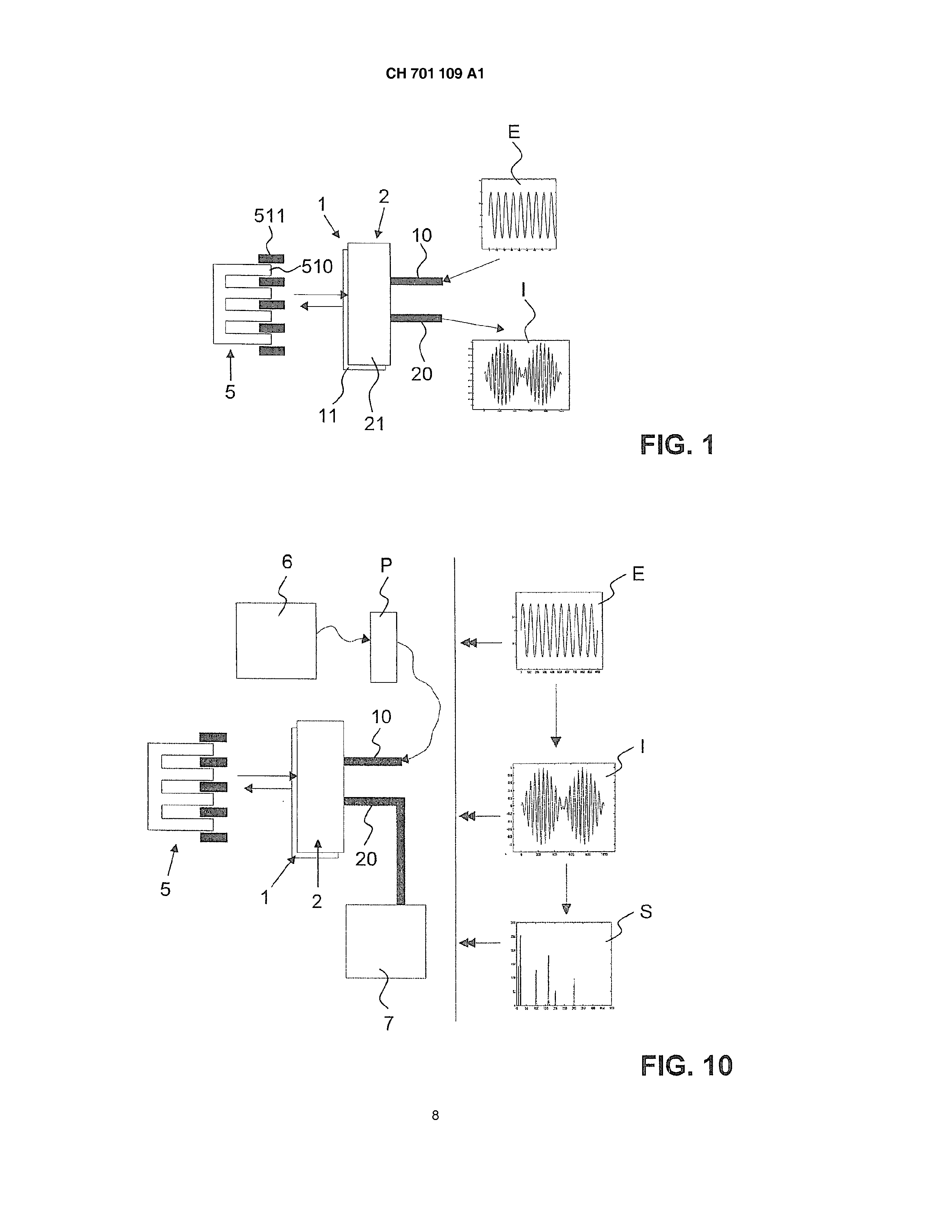
DESCRIPTION of PREFERENTIAL EXECUTION FORMS in Fig. 1 is well recognizable the basic principle of the interferometer according to invention. The reference number 5 designates a laminated lattice unit 5. you exhibits mobile arranged first mirrors of 510 and immovably arranged second mirrors 511, which extend in this example in a row along a straight line. The second mirrors 510 are comblike pushed between the first mirrors 511, so that first beside a second mirror comes to lie in each case. The mirrors 510, 511 preferably exhibit a flat mirror surface. The Spiegeloder reflection surfaces of all mirrors 510, 511 is directly aligned. The mirror surfaces of the first mirrors 510 swore preferably in a common first flat level and the mirror surfaces of the second mirrors swore in a common second flat level. The two levels run preferably parallel zueinander.
The reference number 1 designates a light sending unit, which is connected with here a not represented source of light. The source of light knows a coherent or incoherent, monochromatic, multi color source of light or an instruction source of light sein.
The light sending unit exhibits a multiplicity of light conductors arranged next to each other, which light-along-animal-end on, the laminated lattice unit 5 of turned side in at least one row 11 is arranged. Preferably they are on at least, still more preferentially on exactly one straight line arranged. The light conductors can be led to the source of light as circular or oval bundle 10. The light linked into these light conductors is in the Fig. 1 with E designates. The representation is not full-scale too verstehen.
Light, which from the light conductors 110 one uncouples, arrives perpendicularly or in an angle at the reflection surfaces of the mirrors 510, 511. This is the Auskoppelrichtung.
The reference number 2 designates a light receipt unit, which is likewise by a lighting lead connected with here a not represented evaluation unit. Preferably also the light receipt unit consists of a multiplicity of light conductors, which at the light-receiving end in at least one row 21 is arranged. Preferably they in at least one straight line and still more preferentially are into straight lines exactly arranged. Also this light conductor row 21 can to be preferably rounded or oval bundles 20 be united and so the light to an evaluation unit übermitteln.
Light, which is reflected by the mirrors, is linked in the linking direction preferentially into the light receipt unit. This linking direction is preferably perpendicular to the Reflexionsoder mirror surface. It can lie also in an angle in addition. In case of an angle the angle between that is light uncoupling light conductor row 11 and the reflection surface approximately equal to the angle between that light linking light conductor row 21 and the reflection surface, however with other Vorzeichen.
As light conductors for the light sending unit and for the light receipt unit monomode fibers are suitable if necessary or Multimodefasern.
Light, which arrives now from the source of light into the light conductor row 11 of the light sending unit 1, is directed directly toward the mirrors 510, 511 of the laminated lattice 5. There it is reflected by all mirrors 510, 511. Since the first group of mirrors of 510 exhibits another distance to the first light conductor row 11 than the second group of mirrors of 511, it gets off to a phase shift of the reflected light, dependently, at which mirror the individual ray of light was reflected. The reflected light with the two different phases arrived at the light receipt unit 2. it is passed on to the evaluation unit 7, where changes in the light intensity are detected. Preferably first a phase correction is accomplished. The interference is in Fig. 1 schematically represented and with the reference symbol I versehen.
This interferometer actually needs no further optical construction units in the path of rays between light sending unit and mirror and/or between mirrors and light receipt unit. Preferably also no further optical construction units are in the ranges mentioned of the interferometer present. However further optical construction units, as for example filters, can do lenses or steel divisors, used werden. depending upon application
In Fig. a spectrometer is schematically represented 10. Additionally to mentioned above the interferometer it covers a source of light 6 and an evaluation unit 7. the source of light 6 sends light into the first light conductor bundle 10. the path of rays is in the Fig. not straight-lined represented. It can be turned back, does not have however not compellingly, by means of optical elements. The evaluation unit 7 detects the reflected light and evaluates it. In the Fig. 10 is spectra of S dargestellt.
One sample P which can be determined is preferably between source of light 6 and light linking unit 1 angeordnet.
It can however also between light uncoupling unit 2 and evaluation unit 7 arranged sein.
Into the Fig. a first remark example of the interferometer according to invention is represented 2 and 3. The laminated lattice unit 5 is M of EMS a based structure with a framework or G round body 50 and a first mirror side 51 with two mirror sets 510, 511 einstückig angeformten to it. It can exhibit second, opposite directed mirror side 51 " and be symmetrically trained altogether. A such structure is for example in the initially mentioned WHERE 2006/000120 descriptive. Typical lengths of the mirror row 51 amount to 3,5 to 4 mm. Typical widths and heights of the individual mirrors 510, 511 lie in the micrometer range. Preferred the widths of the individual mirrors 510, 51112 amount to over and the heights 75 to 100 over or even to 150 over. The individual mirrors are together gereiht and devoted in their width so the length of the mirror row. The height of the mirror row preferably corresponds the height of the individual Spiegel.
As in Fig. 3 is recognizable, consists the first mirror side 51 of a number of the first mobile mirrors 510 and a set of relative to the first mirrors stationary second mirrors 511. , specified above
Oppositely to the first mirror row 51 is the light sending unit 1, which exhibits the mirror row 51 turned the light conductor row 11. The light conductor row 11 extends preferentially approximately over the entire width of the first mirror side 51.
This light conductor row 11 exists, as in Fig. 3 is recognizable, from a multiplicity from next to each other arranged light conductors 110. Identical or different light conductors can be used. Preferably are they identically to each other. The light conductors 110 can each other affecting or beabstandet to each other arranged sein.
The individual light conductors 110 of the light conductor row 11 change into a light conductor bundle 10, like this in Fig. 2 is recognizable. This Lichtleiterbünde110 extends into the range of the not represented source of light 6, by which the light is linked into the light conductors. The cylindric element at the upper contour symbolizes the shroud of the light conductor bundle in the example represented here forms the light sending unit 1 also the Lichtempfangseinheit. described above
Also that is, the light conductors 110 send both light and receive the reflected, partial out of phase light. In the range of the source of light 6 also an evaluation unit is present, which evaluates the light sent back over the light conductors. Preferably a beam splitter is present, around the reflected light of the evaluation unit zuzuführen. in this case
Into the Fig. a second remark example is represented 4 and 5. Here the light sending unit 1 and the light receipt unit are 2 two from each other separated units. In the example represented here they are one above the other arranged. The first light conductor row can be arranged 11 over or under the second light conductor row. Depending upon base 50 it is favourable, if the first light conductor row is arranged below second. Preferably both rows 11.21 are trained approximately equivalent long and extend over approximately the entire width of the first mirror side 51.
Preferably the same light conductor types for the light sending unit 1 are used as for the light receipt unit 2. Typical diameters of the light conductors 110.210 amount to 50 - p.m. the diameter that is equal or smaller to 100 preferably light sending light conductor 110 than the height of the opposite mirrors 510, 511. Preferably the diameters are equal or larger to that light receiving light conductor 210 than the height of the opposite mirrors 510, 511.
Again a source of light 6 is present, which light links 1 into the first Lichtleiterbünde110 of the light sending unit. The reflected, partial out of phase light is linked into the second light conductor row 20 of the light receipt unit 2 and arrived over the second light conductor bundle of 20 at the Auswerteeinheit.
In Fig. a further variant is represented 6. Here the second light conductor row 21 of the light receipt unit 2 is longer designed than the first light conductor row 11 of the light sending unit 1. thereby can as much as possible light of the light receipt unit 2 be taken up. The arrangement can however also in reverse sein.
In the remark example in accordance with Fig. 7 exhibits the light conductors 210 of the light receipt unit 2 a larger diameter than the light conductors 110 of the light sending unit 1, in order to take up as much as possible light. The diameter can around a multiple more largely sein.
In Fig. a further remark example is represented 8. Here those are arranged light sending light conductor 110 and the light receiving light conductor 210 alternating next to each other. Preferably in each case a light of receiving light conductors 210. follows a light sending light conductor 110
In Fig. now the receipt unit is not by light conductors, but formed for 9 by a sensor 2 ". This is arranged in the range that light sending light conductor row 11. As sensor in particular a photodetector of well-known Art. is suitable
The execution forms specified above can be interconnected also. In place of only one light conductor row also several light conductor rows can be begun. These rows can expand since curved in place of straight-line distances. The moreover one these rows can be arranged in an angle to each other and in an angle to the mirror surfaces, as long as by the choice of the angles it is guaranteed that sufficient sent light at the mirrors and sufficient reflected light from the mirrors arrive to the receipt unit. So for example light conductors can send and receive both light and receive other light conductors only or aussenden. in a further execution form
These interferometers can be begun in spectrometers with the well-known evaluation methods and application possibilities. Examples for this are: As well as Gasund liquid analyses, water controls, analyses of body fluids such as blood, milk analyses, quality controls in Lebensmittelund farm-but-calibrate Lichtanalysen.
Interferometer according to invention and this interferometer using spectrometers makes an evaluation of relatively much light and it possible exhibits therefore a increased sensitivity. Furthermore only few optical construction units are necessary, the adjustment are relieved and them are economical herstellbar.
BEZUGSZEICHENUSTE 1 light sending unit first light conductor bundle of 11 first light conductor row of 110 first light conductors 2 light receptor unit 2 " photodetector 20 second light conductor bundle of 21 second light conductor row of 210 second light conductors laminated lattice unit base 51 first mirror 51 " second mirror 510 mobile mirror 511 firm mirror 6 source of light 7 evaluation unit E radiated light I to the interference reflected light brought S spectrum An interferometer for generating an interference pattern comprises a lamellar grating unit (5) having reflection surfaces for reflecting light, a light emitter (1) for emitting light to the lamellar grating unit (5), and a light receiver (2) for receiving light reflected by the lamellar grating unit (5). The light emitter (1) comprises a plurality of individual light guides (110), which are arranged in at least one light guide row (111) and send light to the lamellar grating unit (5) in the form of a beam of rays. The beam of rays can be aimed directly at the lamellar grating unit (5). The interferometer according to the invention and the spectrometer using said interferometer enable the evaluation of a relatively large amount of light and therefore exhibit increased sensitivity. Interferometer for the production of an interference sample comprehensively: a laminated lattice unit (5) with reflection surfaces for the reflection of the light, a light sending unit (1) for sending the light on the laminated lattice unit (5) and a light receipt unit (2) for the receipt the laminated lattice unit (5) it reflected light, by the fact characterized that the light sending unit (1) a multiplicity of individual light conductors (110) covered, which are arranged in at least one light conductor row (11) and which light as luminous beams on the laminated lattice unit send (5). 2. Interferometer according to requirement 1, whereby the light conductors (110) the luminous beam directly on the laminated lattice unit (5) arranges. 3. Interferometer after one of the requirements 1 or 2, whereby the light conductors (110) of the light sending unit exhibit (1) everything the same light uncoupling direction, whereby this light uncoupling direction in an angle, preferably approximately perpendicularly, to the reflection surfaces of the laminated lattice unit (5) is aligned. 4. Interferometer after one of the requirements 1 to 3, whereby the light receipt unit (2) a multiplicity of individual light conductors (210) covered, and whereby the reflected light directly on the light receipt unit (2) falls. 5. Interferometer according to requirement 4, whereby the light conductors (210) of the light receipt unit exhibit (2) everything the same light linking direction, whereby this light linking direction in an angle, preferably approximately perpendicularly, to the reflection surfaces of the laminated lattice unit (5) is aligned. 6. Interferometer after one of the requirements 1 to 5, whereby the laminated lattice unit consists of first and a second mirror set (510, 511) with several mirrors, whereby the two mirror sets (510, 511) interlink, as a mirror of the first mirror set (510) beside a mirror of the second mirror set (511) is arranged, and whereby the position of the first mirror set (510) is relative to r situation of the second mirror set (511) VE edgable. 7. Interferometer after one of the requirements 1 to 6, whereby the laminated lattice unit (5) by an micro-electromechanical lattice (MEM lattice) is formed. 8. Interferometer after one of the requirements 1 to 7, whereby the light conductors (110,210) of the light receipt unit (2) and/or the light sending unit (1) along at least one straight line is arranged parallel next to each other. 9. Interferometer after one of the requirements 1 to 8, whereby at least one part of the light conductors (110) of the light sending unit (1) at the same time at least one part of the light conductors (210) of the light receipt unit form (2). 10. Interferometer after one of the requirements 1 to 8, whereby the light conductors (110) of the light sending unit (1) only for sending the light and the light conductors (210) of the light receipt unit (2) only for receiving of the laminated lattice unit (5) reflects light is intended. 11. Interferometer according to requirement 10, whereby the light and the light receiving light conductor (210) alternate sending light conductor (110) along at least one straight line alternating. 12. Interferometer according to requirement 10, whereby at least one set of light sending light conductors (110) and at least one set of light receiving light conductors (210) it is one above the other arranged. 13. Interferometer according to requirement 12, whereby rows (11) are one above the other arranged by light sending light conductors (110) and series (21) of light receiving light conductors (210) alternating. 14. Interferometer according to requirement 6, whereby the diameter is light of sending light conductor (110) smaller than or equal as a height one opposite it lying mirror (510, 511) and/or whereby the diameter light of receiving light conductor (210) equal as or than the height one opposite it lying mirror (510,511) is larger. 15. Spectrometer with a source of light and an interferometer in accordance with one of the requirements 1 to 14.