Coverable bogie for rail-mounted vehicle, has two-piece bogie frame whose frame halves are transverse adjustably connected to each other by two telescope-like cross beams at distance to change track width
[0001] The available invention concerns a around-purable bogie for rail-mounted vehicles in accordance with the generic term of requirement 1, a procedure for the Umspuren of a bogie as well as a Umspuranlage.
In the special the available invention concerns a around-purable bogie, which are adaptable to different track widths in a stationary Umspuranlage by means of servo units, as well as a procedure for the Umspuren of such Drehgestells.
Umspurfähige of vehicles are well-known and for many years in the use. A common solution is that from patent Talgo with around-purable lot wheel single wheel chassis, which can be umgespurt in an appropriate Umspuranlage of the Spanish Breitspur on the standard gauge and in reverse. Other solutions of the Umspurung are based on the use of special wheel sets, on those the wheels when driving through a stationary Umspuranlage on the axle on another track width to be shifted können.
The solutions mentioned above are however with a Umspurung of the standard gauge on meter-purely and in reverse not practicably, there the way which can be proceeded too largely ist.
A solution for this by the MOBILIZATION (Montreux upper country course) for example in the WHERE 2009/101 023 A1 is suggested. This concerns a bogie with Losrädern, with which the two framework halves are shifted to each other when driving through a stationary Umspuranlage by means of mechanical scenes in the distance, according to the Spurweite. which can be adjusted
This kind around-purable chassis are including the associated Umspuranlagen mechanically very complex and trouble-prone, likewise the Umspurvorgang. A Entpannung in case of of errors with the Umspurung is besides very with difficulty and time-consuming. In addition well-known around-purable chassis are very wear afflicted and with a multiplicity of mechanical components such as joints and feathers/springs provided, those necessarily for the Umspurvorgang werden.
In reverse on the basis of the conditions of the technology specified before the task of the available invention, a around-purable bogie including associated stationary Umspuranlage for the change the track width is to create preferably from standard gauge (1435 mm) on meter pure (1000 mm) and with which the mentioned disadvantages are avoided and a solution everyday life-suited for the rauen railway company to suggest, with that increased the insurance of operation and the track switching times reduced werden.
The task is solved according to invention by a around-purable bogie with a stationary Umspuranlage co-ordinated with it in accordance with requirement 1. A procedure for the Umspuren of normalon meter pure and in reverse is continued to suggest in accordance with the wording of requirement 31.
A around-purable bogie with Losrädern and a two-piece bogie framework is suggested, whereby the framework halves by at least one cross beam in its distance to each other to the purpose of the change of track width crosswise adjustably connected sind.
In accordance with an execution variant it is suggested that the framework halves by two cross beam pipes telescope-like in its distance to each other to the purpose of the change of track width crosswise adjustably connected sind.
Again in accordance with a further execution variant suggested that the two framework halves are changeable by means of place drives integrated in the cross beam pipes, those over a synchronisation system verfügen.
Again further execution variants of the bogie according to invention are in the dependent requirements charakterisiert.
Likewise possible execution variants of the procedure according to invention in the requirements become 31 and the following charakterisiert.
The advantages of the solution according to invention are in the simple conception, for the rauen railway company everyday life-suited design of a around-purable bogie with a stationary Umspuranlage, which both in accordance with the simple, co-ordinated with it, procedure likewise according to invention for the Umspuren of normalon meter pure and in reverse, for the increase of the insurance of operation and the reduction of the track switching times beitragen.
A further advantage of the solution according to invention consists of the fact that the concept of a around-purable bogie with a stationary Umspuranlage and a procedure according to invention also for a track switching between other track widths, for example of standard gauge (1435 mm) on cape pure (1060 mm), co-ordinated with it, of standard gauge (1435 mm) on Breitspur (1520 mm-1524 mm or 1668 mm), or of Schmalspur (1000 mm; 1060 mm) applicably to Breitspur (e.g. 1520 min-1524 mm, 1668 mm) and in reverse ist.
The invention is described afterwards with remark examples on the basis of designs, as well as described their structure and function mode. Show:
Fig. 1:
Fig. 2:
a perspective representation of a bogie according to invention a schematic perspective representation of a bogie according to invention Fig. 3:
Fig. 4:
Fig. 5:
Fig. 6:
Fig. 7:
Fig. 8:
Fig. 9:
Fig. 10:
Fig. 11:
Fig. 12:
Fig. 13:
Fig. 14:
Fig. 15:
Fig. 16:
Fig. 17:
Fig. 18-20:
Fig. 21-22 Fig. 23:
a schematic representation of a bogie according to invention in the plan view a schematic perspective representation of a bogie according to invention with an alternative arrangement and training form of a flexible storage (first feather/spring stage) in a position, those the track width “meter-purely” corresponds a schematic perspective representation of a bogie according to invention with an alternative arrangement and training form of a flexible storage (first feather/spring stage) in a position, those to the track width “standard gauge” corresponds a schematic perspective representation of a bogie according to invention with a bolting device system in a position, those the track width “meter-purely” corresponds a schematic perspective representation of a bogie according to invention with a bolting device system in a position, those the track width “standard gauge” corresponds a schematic perspective representation of a bogie according to invention with a further bolting device system and an amplifier express mechanism for change of track width, in the lowered position of a feather/spring cross beam, in accordance with Fig. 4 for the meter polyurethane enterprise a schematic perspective representation of a bogie according to invention with a further bolting device system and an amplifier express mechanism for change of track width in the increased position of a feather/spring cross beam, in accordance with Fig. 5 supporting arms and to it arranged supporting rollers, represented in a brought in position of the supporting rollers a schematic perspective representation of a bogie according to invention also from a feather/spring cross beam extendable supporting arms and to it arranged supporting rollers, represented in a driven out position of the supporting rollers a principle representation in the opinion from above on a track switching mechanism according to invention a sectional view in the Stirnansicht, extendable for the standard gauge enterprise a schematic perspective representation of a bogie according to invention also from a feather/spring cross beam, by a side of a track switching mechanism for the elucidation of the operational principle with the raising of a track switching guidance due to load by the supporting rollers a schematic perspective representation of an execution form of the track switching mechanism according to invention a schematic perspective representation of a further variant of the track switching mechanism according to invention a schematic perspective representation of a variant for the guidance of a feather/spring cross beam on under it transverseadjustable framework halves a detail opinion of the situation of Fig. 16, from the side regards remark different versions of the training of the cross beams adjustable in itself in a schematic representation in the plan view: remark different versions of the training of to each other adjustable bogie half frameworks in a schematic representation in the Draufsicht.
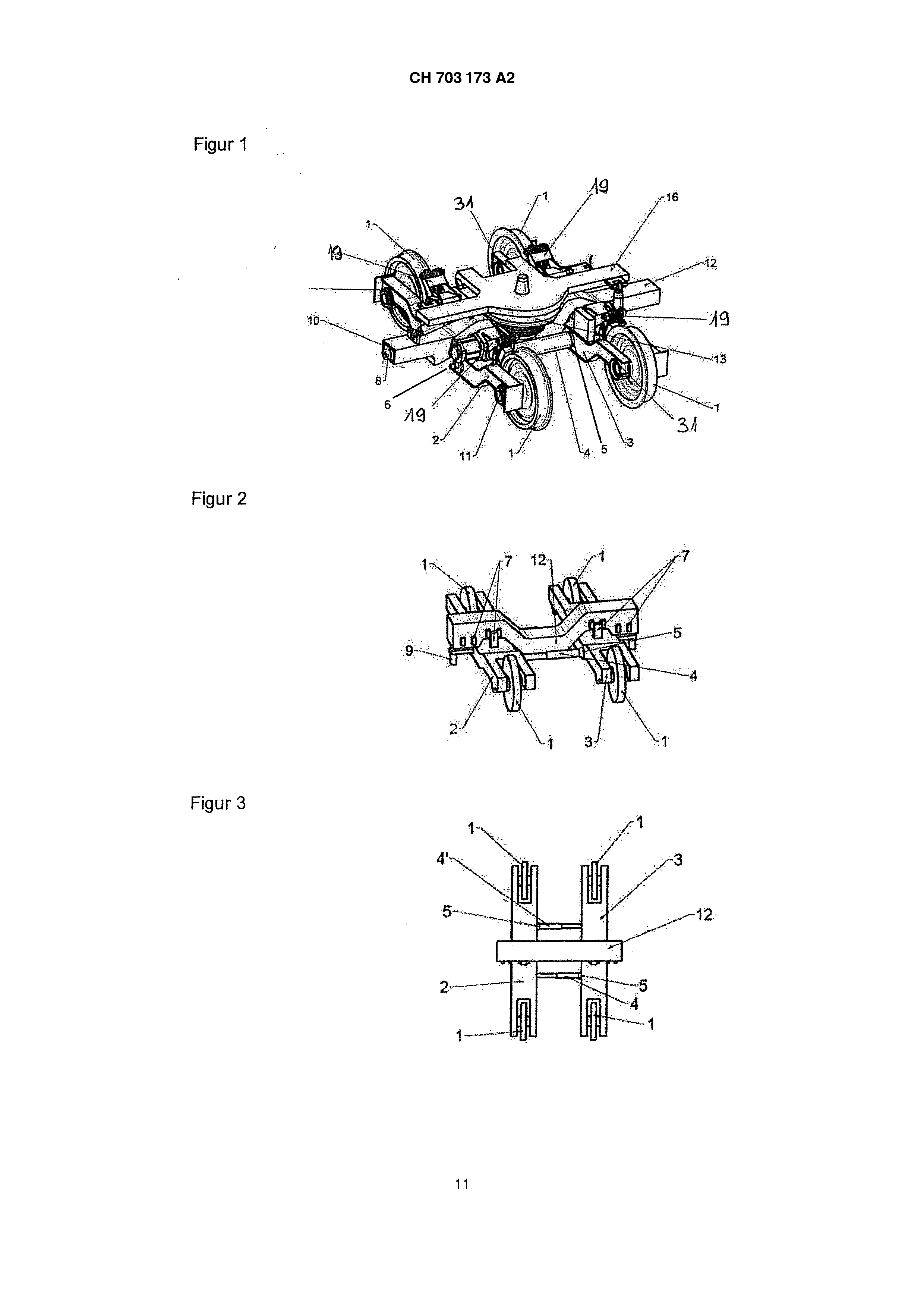
a schematic perspective representation of a bogie according to invention with a further execution variant of the cross beams, adjustable in itself, Fig. 1 to 3 shows the available invention of a around-purable bogie based on the following basic concept:
A around-purable bogie according to invention is equipped with Losrädern 1, its framework halves of 2, 3 by cross beam pipes 4, 4 " in its distance to each other for the purpose of the change of track width is transverseadjustably connected and on those away over flexible camps 11 a bent feather/spring cross beam 12 pushes, which takes up a secondary feather/spring 13 arranged in bogie center, on that a coach body of a rail-mounted vehicle abstürzt.
Primary feather/spring stage a flexible storage (first feather/spring stage) 11 is arranged between the framework halves of 2, 3 and a feather/spring cross beam 12 (Fig. 4, 5). With this variant without Primärfederung between Losräder 1 and turning gesture left framework half of 2, 3 are rigidly fastened to the turning gesture left framework halves of 2, 3 the Losräder 1. In this case a possible track twisting is transferred against each other over a relative turn of the two framework halves 2, 3 by the controlled plays and the Elastizitäten by one sliding bearing each 5. In a further training form the Losräder 1 carry over in each case a Primärfederung 31 on the axle box case one of the turning gesture left framework halves of 2, 3rd alternative for each turning gesture left long side can a Primärfederung also by means of while stationary the technology of well-known rubber-springy wheels trained sein.
The Fig. 4 and 5 shows the arrangement and training form of a flexible storage (first feather/spring stage) 11, which on the framework halves 2, 3 is firmly arranged and pushes on away the feather/spring cross beam 12 in different heights. A position, supported within the bent range of a feather/spring cross beam 12, corresponds thereby for example to the track width “meter-purely” (Fig. 4) and a position, supported at the ends of a feather/spring cross beam 12, corresponds for example to the track width “standard gauge” (Fig. 5). With the variant shown of a flexible storage (first feather/spring stage) 11 the framework halves of 2, 3 without primary feather/spring support themselves directly between axle box cases and framework half on the Losrädern 1 ab.
Bogie framework a around-purable bogie according to invention has two push-pull framework halves 2, 3, which are connected by two for example cross beam pipes 4, 4 telescope-like adjustable in itself " in their distance for the purpose of the change of track width to each other. Is at one end each of the cross beam pipes 4, 4 " a sliding bearing (Fig. 1-3) or sliding camps intended, which can take up controlled plays and its Elastizitäten against each other over its to reconciliation a track twisting a turn of the two framework halves of 2, 3. Alternatively to the sliding bearing (sliding camp) the reconciliation of the track twisting can also by a ball joint at the end of the cross beam pipes perception werden.
Alternatively telescope-like adjustable cross beam pipe 4 can be arranged for example in the transverse center of a bogie, over a change of track width takes place and which to reconciliation a track twisting at an end by a sliding bearing 5 with one of the framework halves of 2, 3 connected ist. between the two framework halves of 2, 3 also only, in itself
Further examples of execution forms of a track width-variable connection of both framework halves of 2, 3 by means of in itself and against each other adjustable cross beams are in the Fig. 18 to 22 dargestellt.
Fig shows. 18 two framework halves of 2, 3 with ever a turningsymmetrically arranged firm cross beam extension 4, 4 ", in their end the transverse shift of the framework halves of 2, 3 to be taken up to each other in each case kann.
Fig. 19 two framework halves of 2, 3, those shows by two interlinking cross beam yokes 14, 14 " at their an end firmly and at its other end as the purpose of the change of track width transverseadjustably trained with the framework halves of 2, 3 connected sind.
Fig. 20 two framework halves of 2, 3, those shows by two interlinking cross beam arms 24, 24 " at their an end firmly and at its other end as the purpose of the change of track width transverseadjustably trained with the framework halves of 2, 3 connected sind.
Fig. the arrangement of two to each other adjustable turning gesture left half frameworks, which are joint lever-like connected by diagonally arranged bars with one another, shows 21. The bars are in each case at an end connected by a ball joint with a half framework and for the purpose of the change of track width at the other end at the half framework Iängsverschiebbar stored. Both half frameworks can equipped with an electromechanical control drive for the Längsverschiebung of the bars sein.
Fig. the arrangement of two to each other adjustable turning gesture left half frameworks, which are connected by diagonally arranged bars, shows 22. The bars are in each case at an end connected by a ball joint with a half framework and for the purpose of the change of track width at the other end at the half framework Iängsverschiebbar stored. Both for example electromechanical control drives for the Längsverschiebung of the two bars are at a half framework befestigt.
Fig. the arrangement of two cross beam pipes 4, 4 telescope-like adjustable in itself shows 23 " as under Fig.
1-3 described, whereby these cross beam pipes 4, 4 are arranged " in the escape of the wheel axles of the Losräder 1 and the two framework halves of 2, 3 in their distance to each other for the purpose of the change of track width transverseadjustably verbinden.
Secondary feather/spring stage over the two framework halves of 2, 3 is crosswise a feather/spring cross beam 12 supported, which for its part takes up a secondary feather/spring 13 arranged in bogie center, on that itself a coach body of a rail-mounted vehicle abstützt.
The secondary feather/spring 13 is for example designed as central airspring with integrated pivot. Alternatively also well-known Stahloder rubber springs, as well as their combinations is conceivable as secondary suspension, which are either central or in pairs toward the ends between a feather/spring cross beam 12 and a coach body of a rail-mounted vehicle arranged. The bent shaping of a feather/spring cross beam thereby 12 made possible the different supporting heights, like it for the change of track width in the positions “meter-purely” or “standard gauge” uses wird.
Adjustment device and bolting device system the transverse shift of the two framework halves of 2, 3 take place to each other for the purpose of the change of track width for example by means of electrical control drives 6, which propel in well-known way in each case spindles in the cross beam pipes 4, 4 ". The control drives 6 have well-known synchronisation system, which prevents a blocking of the two framework halves of 2, 3 in the cross beam pipes 4, 4 " with the Umspurvorgang while stationary the technology. In a further training form the transverse shift can be made also by pneumatic or hydraulic control drives or actuators, which in or beside the cross beam pipes accommodated sind.
In the two end positions of the control drives 6 these can mechanically blocked and by an autonomous/active bolting device system 7 electrically, electromagnetically or pneumatically fixed werden.
The Fig. 6 and 7 shows an alternative arrangement and training form of a bolting device system 7, which for example on the framework halves 2, 3 is firmly arranged and this fixes and locks 12 opposite a feather/spring cross beam, in a position, which corresponds to the track width “meter-purely” (Fig. 6), or in a position, which corresponds to the track width “standard gauge” (Fig. 7). With the raising of a feather/spring cross beam 12 Kraft on the bolting device systems 7 one solves automatically. By vertical positioning of a feather/spring cross beam 12 on the framework halves 2, 3 the bolting device systems 7 are aligned automatically for the selected track width. By lowering the framework halves of 2, 3 are brought to a feather/spring cross beam 12 on the desired track width and at the same time by the bolting device systems 7 automatically fixiert.
The Fig. 8 and 9 shows a further arrangement and training form of a bolting device system 7, which for example at a feather/spring cross beam 12 and this is firmly arranged in relation to the framework halves of 2, 3 fixiert.
At the framework halves far per an adjustment device 9 is arranged of 2, 3 firmly, which intervenes in a track switching mechanism 22, in a position, which corresponds to the track width “meter-purely” (Fig. 8) and in a position, which corresponds to the track width “standard gauge” (Fig. 9).
The manipulation of a bolting device system 7 can either mechanically e.g. via a backdrop and/or a ramp, or in actually well-known way electrically, electromagnetically or pneumatically take place. The bolting device system 7 of the two framework halves of 2, 3 serves for it, the selected track width (meter pure/standard gauge) before and after passing a Umspuranlage according to invention 20 reliably beizubehalten.
The concept it is in such a way laid optional bogie equipment out that a around-purable bogie according to invention both when run bogie or also motorized be implemented can. Here a motorizing of each Losrades is 1 with for example into the wheel hub integrated and while stationary of the technology as wheel hub engine admitted drive possible. Alternatively an engine can be flanged on to each Losrad 1, or the two Losräder 1 of a same framework half of 2, 3 can be propelled by a common engine. Is just as an engine arranged at the coach body conceivable, whereby a drive on the Losräder 1 over cardan shafts erfolgt.
The concept is laid out further in such a way that a bogie according to invention can take up different brake equipment. These can preferably be implemented as wheel-center disk brake, or shaft disk brakes can be flanged on in well-known manners to the Losräder 1. Well-known block brake units 19 or a conventional Gestängebremse are likewise conceivable. In addition a gear wheel brake system can be fastened to each framework half 2, 3. The forces can be divided on both framework halves of 2, 3 over a longitudinal force photograph arm, which affects the two framework halves 2, 3, in the closest track width position (meter pure). Just as an installation of a magnet slipper brake, as well as an arrangement can intended by additional equipments as Spurkranzschmierung, Sander, antennas, etc. at the two framework halves 2, 3 werden.
Umspurvorgang a procedure according to invention described with reference to Fig. 10 and the following to the Umspuren of the around-purable bogies stressed with the available invention basedly on the following basic concept and runs off in several sequences:
a) A vehicle is pulled or pushed into a stationary Umspuranlage according to invention 20. A track switching guidance 22 is lowered in the initial state to knock against thereby for example railscrappers or antennas of locomotives without over it away drives können.
b) c) d) e) as in Fig. 11 represented, is driven out or folded up due to a mechanical or electrical instruction at the ends of a feather/spring cross beam of 12 integrated supporting arms 10 including the supporting rollers arranged to it 8. The latters roll then on printing courses 21, those for example in ramps 23 are spring-tensioned arranged and lift thereby a track switching guidance 22 on (Fig. 13). The mechanical release can be made alternatively also electrically or pneumatically and a raising of the track switching guidance 22 by electromechanical control drives, pneumatic or hydraulic actuators causes respectable auslösen.
Adjusting the framework halves of 2, 3 takes place after raising of the track switching guidance 22 with the help of one in this led amplifier express mechanism 9 (see also Fig. 8 and 9).
The rear-end collision of the supporting rollers 8 on the ramps 23 has also as a consequence that a feather/spring cross beam 12 is raised including the coach body of a rail-mounted vehicle. The two framework halves of 2, 3 remain however on their, on the Losrädern 1 supported Niveau.
Alternatively can also, as in Fig. 14 represented, if a vehicle is completely raised, in place of the track switching guidance 22 an appropriate electrical instruction takes place, with which control drives are set 6 on, the two framework halves of 2, 3 of a bogie to a new track width to adjust and by means of a bolting device system 7 in this position sperren.
After a new track width is adjusted, a vehicle becomes according to the form of a track switching guidance 22 the track abgesetzt.
The sequence of the Umspurung is both from meter on standard gauge and from normalon meter pure for both amplifier left cycles gleich.
The Fig. 10 and 11 shows a around-purable bogie according to invention with a feather/spring cross beam 12, which exhibits at the front side swing-out or extendable supporting arms 10 also at these arranged supporting rollers 8, represented in a brought in position (Fig. 10) and a driven out position of the supporting rollers 8 (Fig. 11).
The Fig. 16 and 17 shows possible training as safe leading of a feather/spring cross beam 12 on the transverseadjustable framework halves present under it 2, 3 by means of a positive connection 25, those with a around-purable bogie according to invention for example as “dove tail guidance” or as groove feather/spring guideway trained its kann.
Umspuranlage a stationary Umspuranlage according to invention 20 is in accordance with the Fig. 12 and 13 on both sides equipped outside of the tracks (meter pure/standard gauge) with ramps 23, which raise the feather/spring cross beam 12 and thus the coach body over the supporting rollers 8. With the ramps 23 the vehicle weight is taken up and the vertical movement /Abst ützhöhe of a feather/spring cross beam 12 is secured, which is necessary for the Ånderung of the position of the two framework halves 2, 3 on another track width. Within the range of the track switching guidance 22 the ramps 23 one printing course exhibit each 21, which for example track switching guidance 22 trained with an u-shaped is located in effect connection (Fig. 13). During load of the printing courses 21 by the supporting rollers 8 the track switching guidance 22 is raised. Alternatively to it the signal for the raising of the track switching guidance 22 can be made also electrically or pneumatically and the raising by electromechanical, pneumatic or hydraulic control drives respectable actuators erfolgen.
Alternatively a track switching guidance 22 can exist of two parallel led bars, or be implemented as a cut open pipe, in which an amplifier express mechanism 9 trained as ball led wird.
The size of the vertical movement can be selected, in order to vary the supporting height of the feather/spring cross beam 12 depending upon track width. Thus the height of a rail-mounted vehicle can in particular during bent shaping of the feather/spring cross beam varied and e.g. for different platform heights adapted werden.
The ramps 23 provided with printing courses 21 do not have to exhibit compellingly an ascending outline, on which the supporting rollers 8 of a feather/spring cross beam 12 highly to run and a coach body raise. A further execution form consists of the fact that the bogies with the two framework halves of 2, 3 are lowered in a pit, while a coach body and a feather/spring cross beam 12 on a same level bleiben.
Far ability the ramps 23 so conceived its that they carry the bogies forward with the change of the track width, by them for example equipped with a chain, roles or other Auflageund Übertragungselementen sind.
Fig. 14 a possible execution form of a Umspuranlage according to invention 20, with which the Losräder 1 are led in track width-variable channels 16, shows by mechanically, electrically, electronic or hydraulically operatable adjusting elements 18 to a new track width (meter pure/standard gauge) to be adjusted and the framework halves 2, the 3 opposite a feather/spring cross beam 12 in transverse direction pushed together (meter-purely) or pulled apart (standard gauge) werden.
Fig. 15 a further execution form of a Umspuranlage according to invention 20 shows, with the one around-purable bogie according to invention over moving in opposite directions rotating castor volumes 17 to a new track width (meter pure/standard gauge) adjusted and the framework halves of 2, 3 dependent on the direction of travel of the castor volumes 17 opposite a feather/spring cross beam 12 in transverse direction is pushed together (meter-purely) or pulled apart (standard gauge) werden.
With the execution forms represented in the Fig. 1-23 concern it only possible examples of around-purable bogies according to invention for the better understanding of the available invention. The invention is naturally not limited to the represented remark examples. Also for example in or three-axis bogies, different drive mechanisms for adjusting the wheel positions, different training of the descriptive feather/spring cross beams, material choice, etc. etc. are not conceivable are also the invention under any circumstances on Umspuren between meter pure and so-called standard gauge limited, but the invention is suitable for the Umspuren of any bogies between all well-known different track widths. Also for propelled bogies, as for example with tramcars, locomotives, is the available invention for the Umspuren geeignet.
Reference symbol list 1 Losräder 2, 3 framework half of 4, 4 " cross beams (pipes) sliding bearing/sliding camp of 6 control drives 7 bolting device system 8 supporting rollers 9 adjustment device of supporting arms 11 flexible storage 12 feather/spring cross beam 13 secondary feather/spring of 14, 14 " cross beam yokes 16 channel 17 castor volume 18 adjusting element 19 block brake unit Umspuranlage 21 printing course 22 track switching guidance 23 ramps 24, 24 " cross beam connection positive connection 31 Primärfederung The bogie has a two-piece bogie frame whose frame halves (2, 3) are transverse adjustably connected to each other by two telescope-like cross beams (4) at a distance to change track width from 1435 mm for a standard gauge to 1000 mm for a meter gauge. Each half comprises symmetrically arranged cross beam extensions, two interlinking cross beam yokes or cross beam arms. A control drive (6), a locking system, an adjustment device and a positive connection are utilized for changing the distance between the halves. Independent claims are also included for the following: (1) a system for covering a bogie (2) a method for covering a bogie. 1. Umspurbares bogie marked by Losrädern and a two-piece bogie framework, thereby that its framework halves [2, 3] over at least one cross beam (4, 4 "; 14, 14 "; 24, 24 ") in their distance to the purpose of the change of track width to each other is transverseadjustably connected. 2. Turningplaced according to requirement 1, by the fact characterized that the framework halves (2, 3) by two cross beam pipes (4, 4 ") telescope-like in their distance crosswise to the purpose of the change of track width adjustably connected is to each other. 3. Umspurbares bogie after one of the requirements 1 or 2, by the fact characterized that the two framework halves [2, 3] are transverseadjustably connected to each other by two telescope-like cross beam pipes [4, 4 "] in their distance for the purpose of the change of track width, which is arranged in the escape of the wheel axles of the Losräder. 4. Umspurbares bogie after one of the requirements 1-3, by the fact characterized that the two framework halves [2, 3] ever a turningsymmetrically arranged cross beam extension [4, 4 "] or two interlinking cross beam yokes [14, 147 or cross beam arms [24, 247 and with these at their in each case are firmly connected and of them exhibit an end different ends as the admission a transverse shift of the framework halves [of 2, 3] in each case are to each other trained. 5. Umspurbares bogie after one of the requirements 1-4 to arrange thereby characterized that bogie-lateral means [6, 7, 9, 25] are intended, in order the distance between the two framework halves [2, 3] changeable. 6. Umspurbares bogie after one of the requirements 1-5, by the fact characterized that the distance between the two framework halves [2, 3] by means of in the cross beam pipes [4, 47 integrated control drives is changeable, which have a synchronisation system. 7. Umspurbares bogie after one of the requirements 5 or 6, by the fact characterized that the two end positions of the control drives are mechanically blockable and by an autonomous of /aktives bolting device system electrically, electromagnetically or is pneumatically operatable secured, in order to maintain a selected track width surely. 8. Umspurbares bogie after one of the requirements 1-7, by the fact characterized that a possible track twisting over a relative turn of the two framework halves [2, 3] against each other of ever a sliding bearing (sliding camp) is taken up, which in each case an end of the cross beams [4, 47 between these and the two framework halves [of 2, 3] is arranged. 9. Umspurbares bogie after one of the requirements 1-8, by it characterized that the two-piece bogie framework pushes away with its framework halves [2, 3] over a primary feather/spring stage on Losrädern, or the Losräder are equipped with rubber-springy wheel tires. 10. Umspurbares bogie after at least one of the requirements 1-9, by the fact characterized that a flexible storage between the framework halves [2, 3] and a feather/spring cross beam is arranged. 11. Umspurbares bogie after at least one of the requirements 1-10, by the fact characterized that a flexible storage on the framework halves [2, 3] is firmly arranged and is a feather/spring cross beam dependent on the adjusted track width in different heights on the flexible storage supportable. 12. Umspurbares bogie after at least one of the requirements 1-11, by the fact characterized that on the two framework halves [2, 3] a feather/spring cross beam pushes away, which takes up a secondary feather/spring, arranged in bogie center, on which a coach body of a rail-mounted vehicle pushes away, whereby for example the secondary feather/spring consists of a central airspring, alternatively of Stahloder rubber springs as well as their combinations, which are either central or in pairs toward the ends between the feather/spring cross beam and the coach body of a rail-mounted vehicle arranged. 13. Umspurbares bogie after at least one of the requirements 1-12, by the fact characterized that a feather/spring cross beam exhibits a bent shaping with different supporting heights for a flexible storage for change of track width for different positions. 14. Umspurbares bogie after at least one of the requirements 1-13, by the fact characterized that a bolting device system on the framework halves [2, 3] is firmly arranged and this opposite a feather/spring cross beam in different, the track width change adapted positions fixable and lockable is. 15. Umspurbares bogie according to requirement 14, by the fact characterized that by the raising of a feather/spring cross beam automatic release of the bolting device systems ['7] is causable and takes by vertical positioning of a feather/spring cross beam on the framework halves [2, 3] this a desired track width, whereby the adjustment and adjustment of a bolting device system are automatically the result. 16. Umspurbares bogie after one of the requirements 14 or 15, by the fact characterized that a bolting device system is for the adjustment and adjustment of the framework halves [2, 3], as well as for the safe retention of a selected track width, mechanically via a backdrop and/or a ramp, or electrically, electromagnetic and/or pneumatically operatable. 17. Umspurbares bogie after at least one of the requirements 1-16, by the fact characterized that at both framework halves [2, 3] outward an amplifier express mechanism for the interference is arranged on a desired track width into a track switching mechanism for the purpose of the adjustment. 18. Umspurbares bogie after at least one of the requirements 1-17, by it characterized that to safe leading of a feather/spring cross beam on the transverseadjustable framework halves of E2, 3 present under it] a positive connection, arranged is, which is designed for example as “dove tail guidance” or as groove feather/spring guideway. 19. Umspurbares bogie after at least one of the requirements 1-18, by the fact characterized that outside a motorizing of a Losrades with a wheel hub engine or with one, to each Losrad takes place flanged on engine. 20. Umspurbares bogie after at least one of the requirements 1-18, by the fact characterized that the drive of the two Losräder of a same framework half [2, 3] takes place via a common engine. 21. Umspurbares bogie after at least one of the requirements 1-18, by the fact characterized that the drive of a around-purable bogie takes place via an engine arranged at the coach body by means of cardan shafts on the Losräder. 22. Umspurbares bogie after at least one of the requirements 1-21, by it characterized that a Losrad exhibits a wheel-center disk brake, or which a wave brake disk is flanged on and/or which for each Losrad is intended a block brake unit. 23. Umspurbares bogie after at least one of the requirements 1-22, by it characterized that at the two framework halves of E2, 3] a magnet slipper brake and/or the arrangement by additional equipments such as Spurkranzschmierung, Sander, antennas, etc. intended are. 24. Umspuranlage to the Umspuren of a bogie after one of the requirements 1-23, by the fact characterized that in a stationary Umspuranlage (20) mechanisms and/or means are intended to from each other or to each other inducing the two framework halves (2) to the purpose of the change of track width. 25. Umspuranlagen according to requirement 24, by the fact characterized that a stationary Umspuranlage (20) is equipped on both sides outside of the tracks with ramps, which one printing course exhibit each, which stands with an u-shaped trained track switching guidance for the admission of the vehicle weight in reciprocal effect and on another track width secures the vertical movement of the feather/spring cross beam for the change of the position. 26. Umspuranlage after at least one of the requirements 24 or 25, by it characterized that a track switching guidance consists of two parallel led bars, or as a cut open pipe for the guidance of an adjustment device, designed as ball, implemented is. 27. Umspuranlage after at least one of the requirements 24-26, by it characterized that for leading the Losräder track width-variable channels it is intended, and these by mechanically, electrically, electronic or hydraulically operatable adjusting elements on a new track width (meter pure/standard gauge) adjustable sind.
Umspuranlage after at least one of the requirements 24-27 to push together or pull apart thereby characterized that means are intended, in order the framework halves [2, 3] opposite a feather/spring cross beam in transverse direction. 29. Umspuranlage after at least one of the requirements 24-28, by it characterized that moving in opposite directions rotating castor volumes are intended, with which a around-purable bogie on a new track width (meter pure/standard gauge) is adjustable. 30. Umspuranlage according to requirement 29, by the fact characterized that the framework halves [2, 3] are dependent on the direction of travel of the castor volumes opposite a feather/spring cross beam in transverse direction collapsibly (meter-purely) or pull apartable (standard gauge). 31. Procedure for the Umspuren of a bogie after one of the requirements 1-23, by the fact characterized that for the purpose of the change of track width the two framework halves (2, 3) by means of at least one cross beam in their distance to be shifted to each other or from each other crosswise. 32. Procedures according to requirement 31, by it characterized that due to a mechanical, electrical or pneumatic instruction in a feather/spring cross beam integrated supporting arms drive out including the supporting rollers, arranged to it, or fold up, and on spring-tensioned printing courses unreel the latters and raise a track switching guidance. 33. Procedure after one of the requirements 31 or 32, by the fact characterized that on both sides at the bogie an adjustment device intervenes in a track switching guidance of a Umspuranlage and effected via the raising of the track switching guidance adjusting the framework halves [2, 3] .auf the desired track width. 34. Procedure after one of the requirements 31-33, by the fact characterized that the rear-end collision of the supporting rollers causes a raising of a feather/spring cross beam on the ramps including the coach body of a rail-mounted vehicle, while the framework halves [2, 3] on their, on which supported level remains for Losrädern. 35. Procedure after at least one of the requirements 1-34, by the fact characterized that the control drives are set by an electrical instruction on and both framework halves [2, 3] of a bogie adjust to a new track width and these are fixed by means of a bolting device system in this position. 36. Procedure after at least one of the requirements 1-35, by the fact characterized that the sequence of the Umspurung is alike both from narrow on Breitspur and from broad on Schmalspur for both amplifier left cycles. 37. Procedure after at least one of the requirements 31-36, by the fact characterized that due to a mechanical or electrical instruction the appropriate vehicle from both side by means of brackets, which intervene under the shrink points of the coach body and which coach body while driving by the Umspuranlage (in the sense of a clock promoter) raises and continues to transport, while the bogies are umgespurt. 38. Use of the procedure after one of the requirements 31-37 to the Umspuren of a bogie after one of the requirements 1-23 with a stationary Umspuranlage for track switchings, co-ordinated with it, between Meterund standard gauge as well as further track widths, as for example of standard gauge (1435 mm) on cape pure (1060 mm), or standard gauge (1435 mm) on Breitspur (1520 mm) or Schmalspur (1000 mm; 1060 mm) to Breitspur (e.g. 1520 mm) and is in reverse applicable.