Adaptive suspension control for a motor vehicle
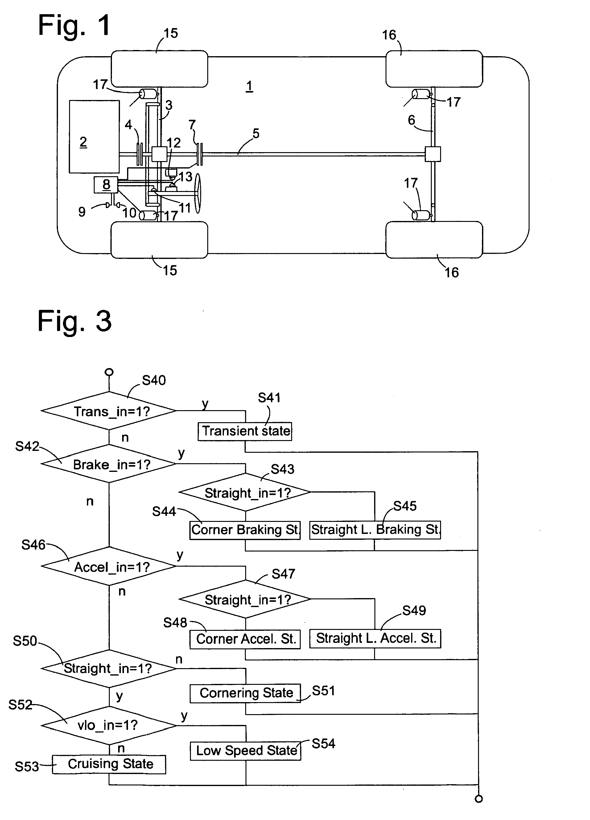
The present invention relates to a suspension control system for a motor vehicle which is capable of varying the suspension stiffness in a moving vehicle and to a method of controlling such a suspension system. The object of the present invention is to remedy this defect and to provide a suspension control system and a control method which allow to combine excellent cornering manoeuvrability with a high degree of comfort. This object is achieved by a suspension control system for a motor vehicle having a chassis and wheels connected to the chassis by a suspension system the stiffness of which is variable under the control of a suspension control system, characterized in that a controller of this control system is adapted to modify autonomously the stiffness of the suspension system depending on a current state of motion of the vehicle. Since the suspension control system will always use a first degree of stiffness e.g. when cruising and another degree of stiffness, e.g. when cornering, a driver will usually not notice that the stiffness is being switched, since he will never experience cornering with the first degree of stiffness. The driver's experience will be that of a vehicle suspension which combines a high degree of comfort while cruising with exceptional manoeuvrability while cornering or in transient situations. In order to recognize cornering, the controller is preferably connected to a lateral acceleration sensor and is adapted to distinguish between a high lateral acceleration state of motion and a low lateral acceleration state of motion and to set a higher stiffness of the suspension system in the high lateral acceleration state than in the low lateral acceleration state. Similarly, the controller may be connected to a yaw rate sensor and be adapted to distinguish between a high yaw rate state of motion and a low yaw rate state of motion and to set a higher stiffness of the suspension system in the high yaw rate state than in the low yaw rate state. The controller may also be adapted to estimate the side-slip rate of the vehicle, to distinguish between a high side-slip rate state of motion and a low side-slip rate state of motion and to set a higher stiffness of the suspension system in the high side-slip rate state than in the low sideslip rate state. Preferably, side-slip rate estimation may be based on yaw rate data from the yaw rate sensor and lateral acceleration data from the lateral acceleration sensor. Further, the controller may be connected to a longitudinal acceleration sensor and be adapted to distinguish between a high longitudinal acceleration state of motion and a low longitudinal acceleration state of motion and to set a higher stiffness of the suspension system in the high longitudinal acceleration state than in the low longitudinal acceleration state, in order to provide a tighter grip on a road when accelerating. Similarly, the controller may be adapted to distinguish between a positive longitudinal acceleration state of motion and a negative longitudinal acceleration state of motion, i.e. braking, and to set a higher stiffness of the suspension system in the negative longitudinal acceleration state than in the positive longitudinal acceleration state. When the vehicle is moving slowly, e.g. when manoeuvring into or out of a parking box, it may be appropriate to have a stiffer setting of the suspension system than when travelling at a normal speed for urban or overland traffic. Therefore, the controller may also be adapted to distinguish between a high forward speed state of motion and a low (including negative) forward speed state of motion and to set a higher stiffness of the suspension system in the high forward speed state than in the low forward speed state. In order to recognize transient situations, i.e. situations in which the direction of the vehicle is changing quickly - although for a short time the vehicle may be moving straight ahead - , it is preferred that the controller is connected to a steering wheel angle sensor and is adapted to distinguish between a high steering wheel angular velocity state of motion and a low steering wheel angular velocity state of motion. In a transient state corresponding to the high steering wheel angular velocity, the stiffness of the suspension system should be set higher than in the low steering wheel angular velocity state. For the same purpose, the controller may be adapted to determine a time derivative of the yaw rate, to distinguish between a high yaw rate derivative state and a low yaw rate derivative state and to set a higher stiffness of the suspension system in the high yaw rate derivative state than in the low yaw rate derivative state. Preferably, the states are assigned a plurality of discrete stiffness values of the suspension system. Although the suspension system as such might allow for a continuous variation of the stiffness, selecting discrete values is preferred, because if there are other parameters of the vehicle chassis which are continuously adjusted according to the state of motion of the vehicle, e.g. the distribution of engine torque to front and rear wheels, or the relation between steering wheel angle and the angle of the front wheels steered by it, the number of possible parameter combinations is finite. This enables the vehicle designer to check each combination of parameters for operational safety or other criteria, and to rule out selection of an unfavourable parameter combination. It is further preferred that the controller stores at least to maps for assigning a stiffness value to each state and that it has a user interface for allowing a user to select between said at least two maps. In this way, the user still has a possibility of adapting the behaviour of the vehicle to his personal taste by selecting e.g. between a map optimized for comfort and another optimized for sporty driving. The object is further achieved by a method for controlling the stiffness of a suspension system in a motor vehicle comprising the steps of The invention may be embodied by a data processor program product comprising a data carrier in which program instructions for enabling a data processor to form the controller of the suspension control system described above or to carry out the method described above are recorded in machine readable form. Further features and advantages of the invention will become apparent from the subsequent description of embodiments thereof referring to the appended drawings. Shock absorbers 17 are provided near the wheels 15, 16 on front and rear axles 3, 6. The stiffness of the shock absorbers 17 is variable under control of the controller circuit 8. The controller circuit 8 has a variety of sensors connected to it, such as an acceleration sensor 9 for detecting longitudinal and lateral acceleration of the vehicle 1, a yaw rate sensor 10, a steering wheel angle sensor 11 or an accelerator pedal sensor 12. The accelerator pedal sensor 12 may replaced by an intake air throttle sensor, not shown, or by a fuel supply rate signal from an electronic engine controller, not shown, since throttle position or fuel rate are usually directly controlled based on the accelerator pedal position. Further, a brake sensor 13 is provided. This sensor may detect a position of a brake pedal, or it may be a pressure sensor for detecting the pressure of a brake fluid which is used for driving wheel brakes, not shown, at wheels 15, 16, in a manner familiar to the man of the art. The operation of the controller circuit 8 will be explained referring to the flow charts of In a first step S1, the controller circuit 8 checks whether any electronic stabilizing system which may exist in the vehicle 1, such as a conventional ABS or ESP system is actively interfering with the vehicle controls. If it is, the process of The process of In step S2, controller circuit 8 receives a current measured value of the yaw rate YR from yaw rate sensor 10. In step S3, this value YR is compared to a predetermined low threshold YRmin. If YR is found to be below this threshold, step S4 sets the present value of the yaw rate index YRin(t) equal to zero. If YR is above the first threshold, it is compared to a second, higher threshold YRmax in step S5. If YR exceeds this second threshold, the index YRin(t) is set to 1 in step S6. If YR is below the second threshold YRmax, the index YRin(t) is maintained at the value YRin(t-1) it received in a previous iteration of the process (S7). In a similar way, a steering wheel angle SW is fetched from steering wheel angle sensor 11 in step S8, and, based on a comparison with two thresholds, the present value of a steering wheel index SWin(t) is set to 0, to 1, or is left identical to its previous value SWin(t-1) in step S9. In the same way, the lateral acceleration AY is read from acceleration sensor 9, and a lateral acceleration index AYin(t) is set according to this reading in step S11. Step S12 checks whether any of the indices YRin, SWin, AYin determined above is 1, indicating that the vehicle is going through a curve. If so, a straight line driving index Straight_in is set to 0 (S13), if not, it is set to 1 (S14). In step S15, the current longitudinal acceleration AX is fetched from acceleration sensor 9, and a longitudinal acceleration index AXin(t) is derived therefrom as described above for YR (S16). In the same way, an index APin(t) indicating whether the accelerator pedal is depressed far enough to accelerate the vehicle is determined in steps S17, S18. An index having the same significance might alternatively be derived from the position of an intake air throttle or from the rate of fuel supply to the engine, too. Step S19 checks whether the vehicle is in a braking state or not by either comparing the longitudinal acceleration AX of step S15 to a threshold AXmin or by comparing the brake fluid pressure MCP to a threshold MCPth. If one of these thresholds is exceeded, a braking index Brake_in is set to 1 (S20), else to 0 (S21). If either AXin = 1, indicating a substantial acceleration of the vehicle, or APin = 1, indicating imminent acceleration, and Brake_in = 0, an acceleration index Accel_in is set to 1 (S23), else to 0 (S24). Based on a comparison of the vehicle velocity v with a very low threshold vstopth, a stop index vst_in is set to 1 (S25), indicating that the vehicle is moving, or to 0 (S26), indicating that is practically standing still. If it is determined that the vehicle is moving, its speed v is compared to another threshold vlowth amounting to a few kilometres per hour. If the threshold is exceeded, indicating that the vehicle is moving in a normal traffic flow, the index vlo_in is set to 0 (S28). If v is below vlowth it is likely that the vehicle is carrying out a difficult manoeuvre such as moving into and out of a park box, and vlo_in is set to 1 (S29). In step S30, the yaw acceleration YA, i.e. the time derivative of the yaw rate YR measured in S2, is calculated, and a yaw acceleration index YAin(t) is derived based on comparison with two thresholds in step S31. Step S32 calculates the side-slip rate SS of the vehicle as follows Step S34 calculates the time derivative SA of the steering wheel angle SW. In step S35, a steering wheel velocity index SAin(t) is set to 0 if there is no substantial movement of the steering wheel and to 1 if there is. If SAin(t) is 0 in step S36, i.e. if the steering wheel is turned slowly or not at all it is assumed that the vehicle is not in a transient state. This is reflected by transient index Trans_in being set to 0 in S37. If SAin(t) is 1, step S38 further checks whether at least one of indices YAin(t) or SSin(t) is 1. If this condition is fulfilled, the vehicle is assumed to be in a transient state, i.e. Trans_in is set to 1 in S39. The state of motion of the vehicle thus having been evaluated, the controller proceeds to the second part of the process, illustrated in If the vehicle is not found to be in the transient state, the brake index Brake_in is checked in step S42. If it is 1, the straight line driving index Straight_in is checked in S43. If it is 1, it is concluded that the vehicle is in a cornering braking state, i.e. it is braking while going through a curve, in S44, and a stiffness value associated to this state is set in the shock absorbers 17. If Straight_in = 0 the vehicle must be in a straight line braking state, and the shock absorbers 17 are set accordingly in S45. If the vehicle is not braking the method checks for an accelerating state in S46. If Accel_in = 1 the straight line driving index Straight_in is checked in step S47, and according to the value thereof the vehicle is determined to be in a cornering accelerating state (S48) or in a straight line accelerating state (S49). If the vehicle is not accelerating, either, Straight_in is checked again in step S50, and if it is 1, an appropriate stiffness of the shock absorbers 17 for a cornering state is set in S51. If the vehicle is not cornering, the speed index vlo_in is referred to in S52 in order to decide whether the vehicle is in a cruising state S53 or in a low speed state S54. Table 1 below gives examples of maps by which stiffness values of the shock absorbers can be assigned to the various vehicle motion states determined above. Numbers in table 1 are not quantitative; it is assumed that four different stiffness values referred to as "1" to "4" can be set in the shock absorbers, and that the stiffness increases from "1" to "4". Map A is comfort-oriented; in the cruise mode, the stiffness is set to "1", i.e. very soft. A low intermediate stiffness "2" is predetermined for low speed and straight line acceleration states, whereas all cornering states, straight line braking and transient states have stiffness "3". Map B is more suitable for a sporty driving style, since the shock absorbers are generally set to a higher stiffness than according to map A. Again, the lowest stiffness, "2", is selected in the cruise mode, and the highest, "4", in the transient, cornering and accelerated cornering states. If the controller circuit 8 has a user interface where the driver can specify whether he prefers a comfortable or a sporty driving style, different maps may be used for associating stiffness settings to the various motion states of the vehicle. If the driver selects a comfortable operation mode embodied by map C1, the shock absorbers are set to be soft wherever appropriate, i.e. stiffness "1" is adopted for cruise and straight line accelerating states, whereas all other states are assigned stiffness "2". If the driver wants an intermediate setting, map C2 may be used, which selects the softest setting "1" for the shock absorbers only in the cruise state, and an intermediate value "2" in all others. The shock absorbers are controlled generally to be stiffer by using map C3, which sets stiffness "2" for the cruise mode and "3" for all others. The process described with respect to According to a preferred embodiment, the controller 8 uses the indices obtained in the process of A suspension control system for a motor vehicle (1) having a chassis and wheels (15, 16) connected to the chassis by a suspension system (17) the stiffness of which is variable under the control of the suspension control system comprises a controller (8) adapted to modify autonomously the stiffness of the suspension system (17) depending on a current state of motion of the vehicle. List of reference signs 1. motor vehicle A suspension control system for a motor vehicle (1) having a chassis and wheels (15, 16) connected to the chassis by a suspension system (17) the stiffness of which is variable under the control of the suspension control system, characterized in that it comprises a controller (8) adapted to modify autonomously the stiffness of the suspension system (17) depending on a current state of motion of the vehicle. The suspension control system of claim 1, wherein the controller (8) is connected to a lateral acceleration sensor (9) and is adapted to distinguish between a high lateral acceleration state of motion and a low lateral acceleration state of motion (S10, S11) and to set a higher stiffness of the suspension system (17) in the high lateral acceleration state than in the low lateral acceleration state (S44, S45; S51, S53, S54). The suspension control system of claim 1 or 2, wherein the controller (8) is connected to a yaw rate sensor (10) and is adapted to distinguish between a high yaw rate state of motion and a low yaw rate state of motion (S2-S7) and to set a higher stiffness of the suspension system (17) in the high yaw rate state than in the low yaw rate state (S44, S45; S51, S53, S54). The suspension control system of any of the preceding claims, wherein the controller (8) is adapted to estimate the side-slip rate (SS) of the vehicle (S32), to distinguish between a high side-slip rate state of motion and a low side-slip rate state of motion (S33) and to set a higher stiffness of the suspension system (17) in the high side-slip rate state (S41) than in the low side-slip rate state. The suspension control system of claims 2, 3 and 4, wherein the controller (8) is adapted to estimate the side-slip rate (SS) from the yaw rate (YR) measured by said yaw rate sensor (10) and the lateral acceleration (AY) measured by said lateral acceleration sensor (9). The suspension control system of any of the preceding claims, wherein the controller (8) is connected to a longitudinal acceleration sensor (9) and is adapted to distinguish between a high longitudinal acceleration (AX) state of motion and a low longitudinal acceleration state of motion (S16) and to set a higher stiffness of the suspension system (17) in the high longitudinal acceleration state (S44, S45, S48, S49) than in the low longitudinal acceleration state (S51, S53). The suspension control system of any of the preceding claims, wherein the controller (8) is connected to a longitudinal acceleration sensor (9) and is adapted to distinguish between a positive longitudinal acceleration state of motion and a negative longitudinal acceleration state of motion (S19-S21) and to set a higher stiffness of the suspension system (17) in the negative longitudinal acceleration state (S44, S45) than in the positive longitudinal acceleration state (S48, S49). The suspension control system of any of the preceding claims, wherein the controller (8) is adapted to distinguish between a high forward speed state of motion and a low forward speed state of motion (S27-S29) and to set a higher stiffness of the suspension system in the low forward speed state (S54) than in the high forward speed state (S53). The suspension control system of any of the preceding claims, wherein the controller (8) is connected to a steering wheel angle sensor (11) and is adapted to distinguish between a high steering wheel angular velocity (SW) state of motion and a low steering wheel angular velocity state of motion (S34, S35) and to set a higher stiffness of the suspension system (17) in the high steering wheel angular velocity state (S41) than in the low steering wheel angular velocity state. The suspension control system of any of the preceding claims, wherein the controller (8) is adapted to determine a time derivative (YA) of the yaw rate (YR) (S30), to distinguish between a high yaw rate derivative state and a low yaw rate derivative state (S31) and to set a higher stiffness of the suspension system (17) in the high yaw rate derivative state (S41) than in the low yaw rate derivative state. The suspension control system of any of the preceding claims, wherein the states are assigned a plurality of discrete stiffness values of the suspension system (17). The suspension control system of any of the preceding claims, wherein the controller (8) stores at least two maps for assigning a stiffness value to each state and has a user interface for allowing a user to select between said at least two maps. A method for controlling the stiffness of a suspension system in a motor vehicle comprising the steps of - determining a current state of motion of the vehicle (S1-S39); - whenever a change of the state of motion is observed, setting the stiffness of the suspension system to a value associated to the current state of motion (S40-S54). A data processor program product comprising a data carrier in which program instructions for enabling a data processor to form the controller of the suspension control system of any of claims 1 to 11 or to carry out the method of claim 12 are recorded in machine-readable form.Cruise 1 2 1 1 2 Accel.straight line 2 2 1 2 3 Accel. Corner 3 4 2 2 3 Braking straight line 3 3 2 2 3 Braking corner 3 3 2 2 3 Cornering 3 4 2 2 3 Low speed 2 3 2 2 3 Transient 3 4 2 2 3 List of reference signs
2. combustion engine
3. front axle
4. 1st clutch
5. drive shaft
6. rear axle
7. 2nd clutch
8. controller circuit
9. acceleration sensor
10. yaw rate sensor
11. steering wheel angle sensor
12. accelerator pedal sensor
13. brake sensor
14.
15. front wheel
16. rear wheel
17. shock absorber