Sensor cable and system
The present disclosure relates to a sensor cable comprising a deformable signal line for transmitting a signal, and one or more rigid portions and one or more resilient portions for reversibly deforming the signal line in the cable under the influence of a varying external load on the cable and therewith affecting a signal transmission property of the signal line for transmitting the signal. The present disclosure also relates to a system comprising such sensor cable and to a method. A sensor cable of the above-described type is known from It is noted that further systems comprising optical fibre-based detectors relying on reversible deformation of optical fibres are known from, i.a. Although such devices are generally quite effective, further improvements are desired, e.g. regarding increase of sensitivity and/or reduction of size, manufacturing costs, installation costs and/or operating costs. In view of such desires, a sensor cable, system and method according to the appended claims are provided. In the provided sensor cable, a portion of the cable comprises an axis and a core extending along the axis, a portion of the signal line is helically wound around the core and the rigid and resilient portions are arranged for, under the influence of the varying external load on the sensor cable, reversibly deforming the signal line with respect to the axis. Such sensor cable provides a large signal line length with respect to the sensor cable length which increases sensitivity. The signal line length per sensor cable length can be determined by selecting a core size and a winding pitch of the signal line around the core. The size and/or shape of the core, e.g. the core diameter, and/or the winding pitch may vary along the cable. The varying external load can cause deformation of plural windings of the signal line, increasing signal strength in a system based on the sensor cable. In a sensor cable comprising plural rigid portions, a large density of rigid portions per unit length of the sensor cable may be provided with a lower density of rigid portions per unit length of signal line unit length. This facilitates providing plural well separated zones of deformation along the signal line due to a single rigid portion deforming plural signal line windings and/or a number of (possibly closely spaced) rigid portions deforming plural signal line windings and/or plural portions of a signal line winding, further increasing sensitivity. Further, each deformation in such deformation zone may be kept relatively small and cause relatively low signal level, whereas the combined effect of plural deformations can provide a significantly stronger signal, e.g. comparable to a single large deformation. This facilitates maintaining the signal line deformation well within the range of plastic deformation of the signal line material, increasing robustness of the sensor cable and/or allowing use of relatively delicate signal line material. In the context of this work a portion is considered rigid if it is sufficiently strong and shape-maintaining to act on and deform the signal line against the force of the resilient portion(s) and the proper rigidity and resiliency of the signal line, which, in turn, provide resistance to such deformation and urge the signal line back towards a specific shape and/or geometry with respect to the axis without the external load. The signal line may be an elongated object and the deformation may comprise a lateral bending of the signal line with respect to the direction of elongation. In an embodiment, the signal line comprises an elongated light guide, in particular an optical fibre, more in particular a plastic optical fibre. This enables the use of light as signal carrier, which can be generated, manipulated, shielded and detected by reliable and predictable techniques. Further, optical signals are generally insensitive to electrical and/or magnetic stray fields, but they can be controlled by mechanical means, including deformation of a light guide through which the signals travel to affect the transmitted intensity. Optical fibres are well known and fibres that can guide light with little loss over hundreds meters fibre length are commercially available. Changing a bending radius of an optical fibre can change dispersion and/or loss of light by leaking out of the fibre, which may be detectable. Such dispersion and/or loss may be wavelength dependent. Plastic optical fibres tend to provide somewhat higher damping to glass fibres but they also tend to be significantly cheaper and more robust to bending than glass fibres, in particular repeated bending. One or more of the resilient portions may be formed by portions the signal line itself. This applies in particular if the signal line comprises a plastic object, e.g. a plastic optical fibre, which may exhibit significant inherent resiliency to return to its previous shape when transiently plastically deformed. This facilitates construction of the sensor cable. E.g. a portion of the signal line may be supported over a void in the core so as to be reversibly pressed into the void by one or more of the rigid portions when the sensor cable is subject to a suitable load. For deforming the signal line, in particular by deflection, a suitable rigid portion may be provided by a local hard and/or thick plastic and/or metallic portion, adjacent to a relatively softer and/or thinner portion, e.g. the rigid portions may be provided by a castellated and/or corrugated layer adjacent to the signal line, wherein relatively rigid castellations and/or corrugations are separated by voids and/or spaces (partly) filled with one or more softer material which preferably is resilient to urge the signal line back to a specific configuration. Note that resilient portions may also be provided by the signal line as stated above. The rigid and resilient portions may be arranged for effecting the reversible deformation in a radial direction with respect to the axis. This facilitates use of the sensor cable by arranging the sensor cable generally perpendicular to the (expected) direction of forces from the load. It also allows use of a flexible core, e.g. a longitudinally flexible object, but which preferably is relatively rigid in radial direction, such as a flexible tube, rod, cable, wire and/or monofilament of metal, plastic and/or glass. Such sensor cable can also facilitate manufacture, e.g. by providing an amount of material with rigid portions and one or more layers of resilient material, and winding the signal line around the thus provided core. As an example, at least some of the rigid portions and/or at least some of the resilient portions may be arranged radially inward from the signal line, relative to the axis. This facilitates detection of forces acting on the sensor cable with a substantial radial or tangential component with respect to the axis, e.g. with the sensor cable extending generally perpendicular to the direction of the force to be detected. In a particular embodiment the one or more rigid portions are radially outside the helical portion of the signal line and the one or more resilient portions are radially inside the helical portion of the signal line e.g. being part of a resilient core material. Rigid portions may also or alternatively be provided on or by the core material, or be provided on or by a sheath over the core and the signal line and/or be provided by another layer radially inside or outside of the signal line with respect to the axis. An elongated rib or wire of rigid material extending along the axis, preferably radially outwards of the fibre portion, may provide an series of rigid deformation portions on adjacent windings of the signal line where the latter cross the rib or wire. Rigid portions may be distributed evenly and/or irregularly around the core. In an exemplary embodiment, in at least part of the cable the signal line is wound around the core in a helical pattern with a chirality and a pitch with respect to the axis and the rigid portions are provided in a helical pattern around the core with a different chirality and/or pitch with respect to the axis. Different pitches provide that rigid portions are provided in different rotational positions along the sensor cable axis such that loads from different directions with respect to the cable axis may be detected with increased reliability. The provision of helical patterns with opposite chirality increases, compared to patterns of the same width and pitch but being co-rotating, the density of crossings of the patterns in axial direction and it can reduce the length over which the crossing patterns overlap each other at the crossings. Both effects increase sensitivity, the former by providing more crossing points per unit length of the sensor cable and the latter by providing more clearly located and spatially resolved deformation zones compared to patterns of the same width and pitch but being co-rotating. In an embodiment, the signal line portion is a first signal line portion and the cable also comprises a second signal line portion extending through and/or adjacent the core, thus extending adjacent the first signal line portion. The second signal line portion may be helically wound around the core as well. The first and second signal line portions may be separate lines arranged to transmit signals independently from each other, and need not be of a same type, e.g. the first signal line comprising an optical cable and the second signal line comprising an electrical cable. The first and second signal line portions may be shielded from contact with each other and/or affecting each other, e.g. the second signal line portion extending through the core and the core providing mechanical shielding and/or shielding with regard to signal transmission properties such as electromagnetic shielding. However, the first and second signal line portions may be of similar or identical type. This facilitates use of the sensor cable. When both the first and second signal line portions of the same type but not identical, e.g. having different resistance to deformation and/or affect the signal transmission properties of the signal lines differently the sensor cable may provide an increased sensitivity, reliability and/or dynamic response, and/or more and/or different types of information. E.g. the first signal line portion comprising a broad band optical fibre and the second signal line portion comprising a single mode polarization maintaining optical fibre, or the first signal line portion being used with a continuous signal and the second line portion being used with a time-varying, e.g. pulsed, signal. Further, if the second signal line, the rigid portions and the resilient portions are also arranged for, under the influence of the varying external load on the sensor cable, reversibly deforming the second signal line with respect to the axis, both signal line portions may be used for sensing the load. When both first and second signal lines are deformed under the same load each signal line may be used to check the other and/or when used in combination a stronger sensor signal may be provided, increasing sensitivity of the sensor cable. Further, the first and second signal line portions may be arranged extending generally adjacent each other and being in contact with each other in one or more locations and/or being (locally) separated from each other by a deformable layer. In such cases and if the second signal line is sufficiently rigid, the second signal line may be used to provide at least some of the one or more rigid portions for deforming the helically wound first signal line portion. Also, the first signal line portion may provide one or more rigid portions for deforming the second signal line portion in return. In an example the second signal line portion may be helically wound around the core and over and/or underneath the first signal line portion. As an example, two movably mounted identically crossing optical fibres may, when one is pressed against the other at or near the crossing, provide sufficient mutual deformation to be detectable in either fibre. The first and second signal line portions may be portions of a single signal transmission arrangement, in particular being portions of one signal line such as being portions of one reversed signal line, e.g. a looped optical fibre. This enables arranging both signal input and signal exit ends of the signal line at or near one physical side of the sensor cable, and when both first and second signal lines are deformable under the same load the signal may be combined for checking and or increasing a signal level as outlined before. In a particular embodiment, the first signal line portion is helically wound around the core with a first chirality and pitch with respect to the axis and the second signal line portion is helically wound around the core and the first signal line portion in an opposite chirality and with a different pitch with respect to the axis than the first portion of the signal line. This facilitates manufacture of the sensor cable. In an embodiment, the second signal line portion extends substantially axially along the cable axis and the first signal line portion is helically wound around the second signal line portion, the second signal line portion forming the core around which the first signal line portion is helically wound. This enables construction of a relatively thin sensor cable. In particular when the first and second signal lines are similar or even identical, the first and second signal lines may form rigid portions for mutually deforming the signal lines under the load. In an embodiment, a portion of the core comprises a core axis and a helical groove around the core axis for receiving at least part of the signal line. Thus, the signal line may be partly embedded in the core, defining the position of the signal line relative to the core, protecting the signal line against deformation beyond the domain of plastic deformation and/or facilitating manipulation of the sensor cable. In a particular embodiment said portion of the core also comprises a second helical groove around the core axis for receiving a second signal line portion. Thus, also the second signal line portion may be partly embedded in the core and, besides the aforementioned benefits for each signal line portion, the relative positions of plural signal line portions may be well defined. One or, where applicable, more portions of the grooves in the core may be provided with a (regular or irregular) corrugation arranged to provide the one or more rigid portions. In an embodiment, the core comprises an inner portion and a cover layer, wherein the inner portion comprises a threaded portion with a first chirality and pitch and the cover layer provides the helical groove, wherein the groove has another chirality and/or pitch than the inner portion, such that the helical thread of the inner portion provides corrugations for deforming a signal line received in the groove. In an embodiment having two helical grooves the grooves may be arranged to cross each other and at the positions of the crossings be provided with recesses and/or relatively soft portions, enabling radial movement of signal line portions received in the grooves at the location of the crossings. In an embodiment, the cable comprises a deformable sheath around the signal line and the core, protecting the signal line and core while enabling the desired deformation under the load. In an aspect and in accordance with the above, a system is provided, which comprises a sensor cable as provided herewith and further comprising a source arranged for transmitting a signal through the signal line of the sensor cable and a receiver arranged for detecting at least part of the signal emitted by the source and transmitted through the signal line. Thus, the system provides a sensor for sensing presence of the load complete with signal source and signal detector. Further devices and/or sub-systems may be included also, e.g. one or more power supplies, controllers etc. The system may comprise plural sensor cables which enables sensing loads in plural locations. Preferably, such system comprises plural detectors associated with different sensor cables and/or different signal lines. Optionally the system comprises plural signal sources, e.g. associated with different sensor cables and/or different signal lines. This facilitates installation and operation as the system effectively comprises plural more or less independent sensors. Preferably, the system comprises plural sensor cables arranged closely adjacent each other, in particular parallel to each other. This enables sensing loads in plural locations, and in particular sensing a direction of propagation and/or a velocity of one or more loads, in case the system is provided with a counter and/or a clock. In an embodiment, the source comprises a light source, the signal line comprises a light guide and the receiver comprises an optical receiver. Suitable light sources are arranged for emitting continuous, pulsed and/or modulated light with a wavelength in a range of about 0.1 to 10 micrometers, in particular visible and/or near-infrared wavelengths in a range of about 0.4-2 micrometers, e.g. in one or more ranges of about 400-500 nanometres (blue), 520-550 nanometres (green), 570-590 nanometres (yellow), 630-680 nanometres (red), 800-900 nanometres, 1.2-1.4 micrometers, 1.5-1.6 micrometers or 2-2.2 micrometers (all telecommunication wavelengths); for such wavelengths light sources, in particular Light Emitting Diodes (LEDs) are commercially available. LEDs can provide incoherent or coherent (laser) light with relatively narrow-band spectral width and they tend to be highly versatile and controllable. However, other light sources although polychromatic and/or broad-band light sources are also conceivable. Optical fibres and detectors operating at such wavelengths are also readily commercially available. In the system, one or more detectors may be arranged to detect a signal characteristic that may be affected by deformation of the signal line subject by the load both before and after transmission through the sensor cable, so that signal offsets and/or -drifts may be accounted for. The system may further comprise a controller and at least one signalling device, memory and/or communication device. Suitable signalling devices may comprise counters, warning systems, traffic lights, toll charging devices, cameras, etc. Suitable memories may comprise read only, write only and/or programmable memories, permanent and/or exchangeable. Suitable communication devices may comprise connection ports, transmitters and/or receivers for wireless communication, for authorities-alert systems, remote control systems, etc. In an embodiment, at least part of the sensor cable is arranged in or under a deformable object for supporting a person, in particular a floor mat, a seat, a bed (e.g. in or under a mattress), etc. Such objects may detect at least presence of a person, e.g. for security systems and/or in hospitals to monitor perimeters or restricted areas and/or person behaviour, e.g. patient movement. An embodiment comprises a road having a road surface layer and at least part of the one or more sensor cables is arranged in or under the road surface layer for detecting traffic on the road surface layer. More interestingly, the presently provided sensor cable and system enable use for detecting vehicles on roads for vehicle use, e.g. asphalt or brick roads, when at least part of the sensor cable is embedded in or under the road surface layer. This facilitates robust and/or inconspicuous traffic control. In a particular embodiment, the road has one or more traffic zones, e.g. providing one or more traffic lanes, having a traffic flow direction, and one or more adjacent sensor cables are arranged in or under the road surface layer in one or more of the traffic zones extending substantially transverse to the respective traffic flow direction. Monitoring signals from the plural adjacent sensors facilitates detection of presence and of direction and/or velocity of traffic on the road. The mechanical nature of the present detection mechanism that relies on deformation of the signal line enables operation and use of the system in geometries that would suffer from shielding of electromagnetic signals. As a result, the presently available system can be used with a road having a surface layer, wherein the road has one or more traffic zones and the road surface layer comprises an embedded reinforcement structure, in particular a synthetic or metal reinforcement structure such as metal bars and/or mesh, and wherein the reinforcement structure extends over at least one or more sensor cables arranged in or under the road surface layer in a traffic zone for detecting traffic on the road surface layer. The reinforcement fortifies the road surface layer, in particular an asphalt layer, reducing long-time deformation and/or wear of the layer. It is noted that piezoelectric mechanical sensors exist. However these are expensive and delicate and also larger and less sensitive than the presently provided system. Asphalt road surface layers tend to comprise plural strata, e.g. a bed of sand, one or more rubble or pebble layers and one or more asphalt layers with different compositions with respect to types, sizes and/or concentrations of filler materials. The present sensor cable may be arranged in any one of these strata, provided a stiff, substantially incompressible mechanical connection with the topmost layer in contact with the traffic is provided. Preferably, each sensor cable is embedded in the lowest asphalt-containing layer, so that good mechanical coupling with the topmost layer exists but that maintenance and/or repair of the higher layers can be performed without damaging the embedded sensor cable. In an aspect, a method is provided herewith, comprising arranging at least one of the sensor cables in or under a road surface layer, the method comprising providing a channel in or under the road surface layer for accommodating a sensor cable, wherein the channel is provided from a lateral side of the road. Thus, the road surface layer need not be penetrated from above for which traffic would need to be blocked. Also, possible reinforcement structures may remain intact. The present detector cable, system and method provide a great advantage over existing traffic control systems which rely on electromagnetic induction between passing vehicles and a measuring loop embedded in the road surface layer. Such systems require large detection surface areas and cannot work with metal reinforcement structures between the measuring loop and the vehicles. As a result, the road surfaces around and over the measuring loops are relatively delicate whereas they generally need to be located in the heaviest-used portions of roads, e.g. near traffic lights and/or in road portions that are used by high numbers of passing vehicles and/or that suffer frequent traffic jams. A sensor cable as provided herein may extend for several meters and have a width (e.g. a diameter) of only a few centimetres. A series of two, three or more adjacent parallel sensor cables may require less road surface area in traffic flow direction than a single induction measurement loop. The detection also works with electrically poorly-conductive or insulating loads, which would hardly or not be detectable via induction, e.g. motorcycles and/or largely non-metallic cars. A single bore hole drilled in or underneath a road surface layer would suffice to provide a channel suitably accommodating the cable; remaining spaces may be filled with a suitable filler to fix the cable to the road surface layer and establish mechanical connection to the road surface layer. Such drilling and arranging the sensor cable in the channel may be done while the road is in use and/or while the reinforcement structure remains intact. The above-described aspects will hereafter be more explained with further details and benefits with reference to the drawings showing an embodiment of the invention by way of example.
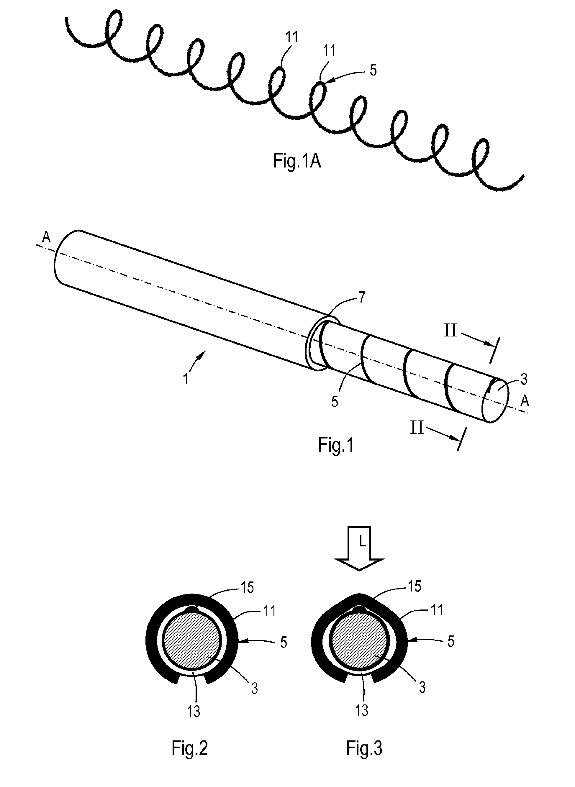
It is noted that the drawings are schematic, not necessarily to scale and that details that are not required for understanding the present invention may have been omitted. The terms "upward", "downward", "below", "above", and the like relate to the embodiments as oriented in the drawings, unless otherwise specified. Further, elements that are at least substantially identical or that perform an at least substantially identical function are denoted by the same numeral. The principle of operation of the sensor cable 1 is indicated in Visible in Each optical fibre 5, 17 is more rigid than the material of (a layer 13 around) the core 3 and the sheath 7 in transverse direction with respect to the direction of propagation of the fibre 5, 17, so that the fibre can flex and bend but is also largely incompressible. Under the influence of a varying external load on the sensor cable 1 (see arrow L in The amount of deformation for each (affected portion of a) fibre 5, 17 is determined by the relative rigidities, flexibilities and/or dimensions of the parts (fibres 5, 17, core 3, sheath 7, grooves 9, layers 13 etc). It may be preferred that the first and second fibres 1, 17 are generally identical, possibly forming part of a single looped fibre (e.g. forward and return signal line portions). Instead of or in addition a second fibre 17, another rigid object with similar position and function to the second fibre 17 may be provided, e.g. a rib or rod, an/or an electric cable, etc. One such rigid object may provide increased sensitivity in one direction, corresponding with the orientation of the rigid object. Plural such rigid objects distributed around the axis A facilitate detection of loads in different directions. It is noted that directionally dependent sensitivity may be beneficial for some situations, e.g. when the sensor cable is to be included in a plane structure for detecting forces within the plane or normal to the plane. At the crossing points the core may comprise relatively soft and/or resilient portions or recesses for accommodating deflection of one or both fibres 5, 17. Also or alternatively and as shown in At the crossings, the effects under influence of a load on the sensor cable 100 discussed with respect to The amount of deformation for each (affected portion of a) fibre 5, 17 is determined by the relative rigidities, flexibilities and/or dimensions of the parts (fibres 5, 17, core 3, sheath 7, grooves 9, layers 13 etc). In the embodiments of Each sensor cable 100 is connected with a source 27 arranged for transmitting a signal through a signal line 5, 17 of the respective sensor cable 100 and a receiver 29 arranged for detecting at least part of the signal emitted by the source 27 and transmitted through the respective signal line 100. The sources and detectors are arranged on a single side of the road. The signal sources 27 and detectors 29 are connected with a controller 31, in turn connected with traffic lights 33, a camera 35, and a wireless communication device 37 comprising a transmitter and a receiver. The controller can also comprise further communication ports and/or user interfaces 39. The road surface layer 21 comprises an embedded reinforcement structure 41, e.g. in the form of a steel grid. The sensor cables 100 are arranged in individual channels extending from a lateral side 43 of the road surface layer. The sensor cables 100 are arranged closely adjacent and generally parallel to each other in the road surface layer 21, wherein the sensor cables 100 extend underneath the reinforcement structure 41 in the traffic zone 23 substantially transverse to the traffic flow direction 25. A suitable manner of arranging the sensors is by drilling a channel into the surface layer 21, inserting the sensors and refilling the channel. Travelling vehicles and/or other traffic on the road surface layer 21 will slightly compress and deform the road surface layer 21, which results in a transient load L on each of the sensor cables 100 in turn, thereby affecting transmission of the signals through each sensor cable 100 as explained before. Such transmission differences due to the varying loads provide a system output signal indicative of the road use. Detection of subsequent signals from the adjacent sensor cables 100 and comparing with clock data provides indications of the actual velocity and travelling direction of a traffic participant, which can be used for controlling switching sequences of the traffic lights 33, photographing traffic offenders with the camera 35 and/or signalling remote systems such as traffic information services and/or warning systems against wrong-way use of a traffic zone 23. The invention is not restricted to the above described embodiments which can be varied in a number of ways within the scope of the claims. For instance a sensor cable may comprise more than two signal line portions, which may provide different helically wound portions, e.g. in identical and/or in different portions of the sensor cable. Size relations may differ, e.g. a smaller core diameter with respect to signal line portion(s). Suitable sizes comprise signal line diameters of about 1-5 mm and core sizes of 1-100 mm. A typical sensor cable for road detection may comprise a plastic optical multimode fibre of 1 mm diameter with a 0.5 mm sheath (i.e. total fibre diameter is 2 mm), wound around a core of glass fibre or foam of about 50 mm diameter and provided with a plastic or copper sheath, embedded in a road surface layer at a depth of about 150-450 mm. Different electromagnetic signals may be transmitted through the signal line portions, e.g. different wavelengths and/or electrical signals through electrically conductive cables, wherein a varying load affects an impedance for time varying signals e.g. reducing pulse rise times and/or delays which may provide detectable dispersion and/or signal skew, in particular in differential signalling arrangements. A (sensor cable of a) system may be partly worked into a fabric, e.g. braided, knitted and/or woven, for detection of movements of a person or an object on the fabric. Comparing a fraction of actually input signals with output of that signal that passed through a signal line may reduce effects of offsets and/or drifts and facilitate detection of slowly changing loads, e.g. the weight of a layer of water and/or snow on a roof. A signal line may comprise a gaseous or fluid medium, e.g. a liquid or a gel wherein a transient load on the Signal line provides a detectable pressure wave and/or damping thereof through the signal line. Various embodiments of the invention, in particular with respect to signal detection and/or processing, operating instructions for the controller etc. may be implemented as a program product for use with a computer system, where the program(s) of the program product define functions of the embodiments (including the methods described herein). In one embodiment, the program(s) can be contained on a variety of non-transitory computer-readable storage media, where, as used herein, the expression "non-transitory computer readable storage media" comprises all computer-readable media, with the sole exception being a transitory, propagating signal. In another embodiment, the program(s) can be contained on a variety of transitory computer-readable storage media. Illustrative computer-readable storage media include, but are not limited to: (i) non-writable storage media (e.g., read-only memory devices within a computer such as CD-ROM disks readable by a CD-ROM drive, ROM chips or any type of solid-state non-volatile semiconductor memory) on which information is permanently stored; and (ii) writable storage media (e.g., flash memory, floppy disks within a diskette drive or hard-disk drive or any type of solid-state random-access semiconductor memory) on which alterable information is stored. Elements and aspects discussed for or in relation with a particular embodiment may be suitably combined with elements and aspects of other embodiments, unless explicitly stated otherwise. A sensor cable is provided comprising a deformable signal line for transmitting a signal, and one or more rigid portions and one or more resilient portions for reversibly deforming the signal line in the cable under the influence of a varying external load on the cable and therewith affecting a signal transmission property of the signal line for transmitting the signal. A portion of the cable comprises an axis and a core extending along the axis, a portion of the signal line being helically wound around the core and the rigid and resilient portions being arranged for, under the influence of the varying external load on the sensor cable, reversibly deforming the signal line with respect to the axis.
Sensor cable comprising a deformable signal line for transmitting a signal, and one or more rigid portions and one or more resilient portions for reversibly deforming the signal line in the cable under the influence of a varying external load on the cable and therewith affecting a signal transmission property of the signal line for transmitting the signal, Sensor cable according to claim 1, wherein the signal line comprises an elongated light guide, in particular an optical fibre, more in particular a plastic optical fibre. Sensor cable according to any preceding claim, Sensor cable according to any preceding claim, Sensor cable according to any preceding claim, Sensor cable according to any preceding claim, Sensor cable according to claim 6, wherein the first signal line portion is helically wound around the core with a first chirality and pitch with respect to the axis and the second signal line portion is helically wound around the core and the first signal line portion with a different chirality and pitch with respect to the axis than the first portion of the signal line. Sensor cable according to claim 6, wherein the second signal line portion extends substantially axially along the axis and the first signal line portion is helically wound around the second signal line portion, the second signal line portion forming the core around which the first signal line portion is helically wound. Sensor cable according to any preceding claim, wherein a portion of the core comprises a core axis and a helical groove around the core axis for receiving at least part of the signal line, and wherein preferably the portion of the core also comprises a second helical groove around the core axis for receiving a second signal line portion. System comprising one or more sensor cables according to any preceding claim and further comprising at least one source arranged for transmitting a signal through a signal line of at least one of the one or more sensor cables and at least one receiver arranged for detecting at least part of the signal emitted by the source and transmitted through at least one of the signal lines, wherein preferably the system comprises plural sensor cables arranged closely adjacent each other, in particular parallel to each other. System according to claim 10, comprising a controller and at least one signalling device, memory and/or communication device. System according to any one of claims 10-11, System according to any one of claims 10-12, System according to claim 13, wherein the road has one or more traffic zones and the road surface layer comprises an embedded reinforcement structure, and wherein the reinforcement structure extends over at least one of the one or more sensor cables in or under the road surface layer in a traffic zone. Method of providing a system according to claim 13 or 14, comprising arranging at least one of the sensor cables in or under a road surface layer, comprising providing a channel in or under the road surface layer for accommodating a sensor cable, wherein the channel is provided from a lateral side of the road.TECHNICAL FIELD
BACKGROUND
SUMMARY
BRIEF DESCRIPTION OF THE DRAWINGS
DETAILED DESCRIPTION OF EMBODIMENTS
wherein a portion of the cable comprises an axis and a core extending along the axis, a portion of the signal line being helically wound around the core and the rigid and resilient portions being arranged for, under the influence of the varying external load on the sensor cable, reversibly deforming the signal line with respect to the axis.
wherein one or more of the resilient portions are formed by the signal line.
wherein
at least some of the rigid portions and/or at least some of the resilient portions are arranged radially inward from the signal line, relative to the axis
wherein in at least part of the cable the signal line is wound around the core in a helical pattern with a chirality and a pitch with respect to the axis and
the rigid portions are provided in a helical pattern around the core with a different chirality and/or pitch with respect to the axis.
wherein the signal line portion is a first signal line portion and the cable comprises a second signal line portion extending through and/or adjacent the core.
wherein at least part of the sensor cable is arranged in or under a deformable object for supporting a person, e.g. a floor mat, a seat and/or a bed.
comprising a road having a road surface layer with one or more traffic zones wherein at least part of the one or more sensor cables is arranged in or under the road surface layer for detecting traffic on the road surface layer, and
wherein in particular the road has one or more traffic zones having a traffic flow direction and wherein one or more adjacent sensor cables are arranged in or under the road surface layer in one or more traffic zones extending substantially transverse to the respective traffic flow direction.