Protective cover has protective piece disposed in housing, at least one light bulb provided in one side of housing, and switch for regulating power source disposed at one end of housing
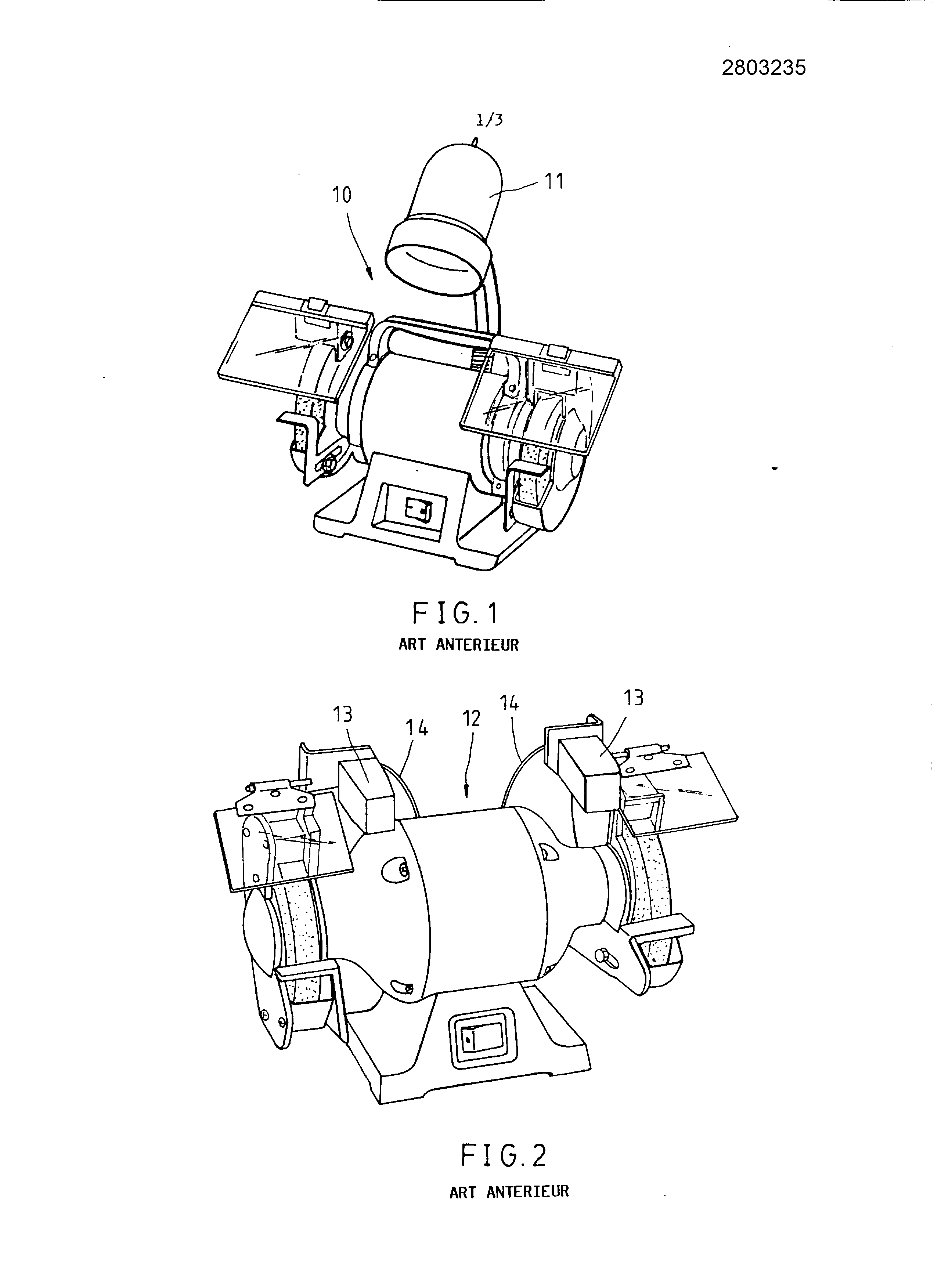
[...] The present invention relates generally to a protective cover for machine tool, and more particularly to a protective cover provided with a lighting apparatus for improving the visibility when the operation of the machine tool. As shown in Figure 1, a conventional grinding machine 10 is provided with a light source 11 capable of illuminating only a certain part of the grinding machine 10. In other words, the light source 11 does that very slightly improves visibility in use of the grinding machine 10. Therefore, the light source 11 is not greatly to the operator of the grinder 10. Today, with reference to Figure 2, another conventional grinder 12 is represented, which comprises two light sources 13, arranged on the right and left of the grinding machine 12. In order to properly place the two light sources 13, additional wires 14 are to be used out of order. Furthermore, the light sources 13 and the shield of the grinding machine 12 are separated from each other, so that the light sources 13 contribute very little to improve visibility and efficiency of the work of the operator. In effect, the light sources 13 on the aesthetic of the grinding machine 12. The first object of the present invention is therefore to provide a protective cover for machine tool having a light device to improve the operating efficiency of the machine tool operator. The addition of the light apparatus does not deleteriously affect the overall aesthetic of the machine tool. The object of the present invention is achieved by a protective cover comprising a housing, a protective glass, a battery holder, and a light device for providing illumination suitable for the working area. The housing is provided with a fixing portion for fixing the protective cover on a specific portion of the machine tool. The present invention provides a protective cover comprising a housing provided with a battery holder and a portion for fastening the light housing on a machine tool; a protective piece of transparent material, disposed within the housing; at least one electric bulb on a side of the housing; and a switch disposed at one end of the housing for switching a power source. The housing may be provided with a receiving compartment, the battery holder can be located in either the receiver compartment, and the attaching portion may be located on a long side of the housing. The housing may further include two arms extending from the other longitudinal side of the housing, which arms are connected by a plate so that the housing, the two arms and the plate form and define a void space; the patch can be placed in a space; and the light bulb may be disposed at about the plate. The case may be formed of an upper housing and a lower housing member whose shape is in correspondence with that of the upper housing; and the patch may be disposed between the upper housing member and the lower casing element. The lower housing member may be provided with a plate which itself is provided with a recess in communication with said empty space, the light bulb disposed in said recess. The patch may be provided on one side with a bulb shield whose location is in correspondence with the recess in said plate, and the light bulb may be disposed between said bulb shield and a plate of the upper housing member. The present invention be included at the reading of the following detailed description of a preferred embodiment, made with reference to the accompanying drawings in which: figure 1 is a perspective view of a grinding machine of the prior art; figure 2 is a perspective view of another grinding machine of the prior art; figure 3 is a perspective view of the preferred embodiment of the present invention mounted on a grinding machine; figure 4 is a exploded view of the preferred embodiment of the present invention; figure 5 is a schematic of the location of the preferred embodiment of the present invention. As shown in Figures 3 to 5, a protective cover made according to the disclosure comprises the parts described hereinafter. A housing 20 is rectangular in shape and consists of an upper housing member 21 and a lower housing member 22 conforming to the shape of the upper housing member 21. The upper and lower housing members 21 and 22 are bonded to each other by a plurality of screws. The housing 20 is provided with a receiver compartment 23, which itself is provided with a bracket 24 assembly for receiving two stacks for electric power source. The upper housing member 21 is provided, in one of its longitudinal sides, a fixing portion 25 for attaching the housing 20 on a machine tool. The housing 20 is provided at both ends of its other longitudinal side of two arms 26 extending in the [...] of the short axis of the housing 20. The arms 26 are provided, at one end, a long plate 27 parallel to the longitudinal direction of the housing 20 for connecting the two arms 26. Therefore, a gap 29 is formed and defined by the housing, the two arms, and the plates long. The long plate 28 of the lower casing element is provided with two long slots 30 in communication with the gap 29. A patch 31 is rectangular in shape and is made of a transparent material, such as acrylic or safety glass. The patch is placed in a space 29 and between the upper housing portion 21 and the lower housing portion 22. The patch 31 is provided with two screens 32 rectangular lamp whose location is in correspondence with the two recesses 30. Two light bulbs 33 are arranged in the two recesses 30 and between the long plate 27 of the upper case and the two screens lamp 32. The light bulbs 33 are Halogen bulbs. A switch 34 is arranged at one end of the receiver compartment 23, to select the states "ON" and "OFF" of a control circuit. A cover 35 is for protecting the receiver chamber 23, to retain the batteries. The protective cover of the present invention is provided with the fixing portion 25 by which the protective cover may be attached to an appropriate portion of a machine tool, without having to use the lamp holder, the bulb shield, the wires, and the like, that often interfere with the operator of the machine. Furthermore, the protective cover of the present invention does not distract from the aesthetics of the machine tool. Furthermore, the protective cover of the present invention provides a suitable illumination to the machine tool or to the work area. A protective piece (30) made of a transparent material is disposed in a housing (20) that is provided with a battery mount (24) and a fastening portion (24) that fixes the housing with a machine tool. At least one light bulb is disposed in one side of the housing. A switch (34) at one end of the housing regulates a power source. 1. A protective cover characterized in that it comprises: a housing (20) provided with a battery holder (24) and a fixing portion (25) for securing said housing on a machine tool; a protective piece (31) of transparent material, disposed in said housing (20); at least one electric bulb (33) placed on one side of said housing (20); and a switch (34) disposed at one end of said housing (20) for switching a power source. 2. A protective cap according to claim 1, characterized in that said housing (20) is provided with a receiver compartment (23), in that said battery holder (24) is located in said receiving chamber (23), and in that said fastening portion (25) is located on a longitudinal side of said housing (20). 3. A protective cap according to claim 2, characterized in that said housing (20) further comprises two arms (26) extending from the other longitudinal side of said housing, which arms (26) are connected by a plate (27) such that said housing (20), said two arms (26) and said plate (27) form and define a void space (29); in that said patch (31) is placed in said empty space (29); and in that said light bulb (33) is disposed at said plate (27). 4. A protective cap according to claim 3, characterized in that said housing (20) consists of an upper housing part (21) and a lower housing member (22) whose shape is in correspondence with that of said upper case; and in that said patch (31) is disposed between said upper housing member (21) and said lower housing member (22). 5. A protective cap according to claim 4, characterized in that said lower housing member (22) is provided with a plate (28) which itself is provided with a recess (30) in communication with said empty space (29), and in that said light bulb (33) is disposed in said recess (30). 6. A protective cap according to claim 5, characterized in that said patch (31) is provided on one of its sides of a display lamp (32) whose location is in correspondence with said recess (30) of said plate, and in that said light bulb (33) is disposed between said screen lamp (32) and a plate of said upper housing member (21). Protective cover for machine tool