DEVICE HAS HYDRAULIC VALVES
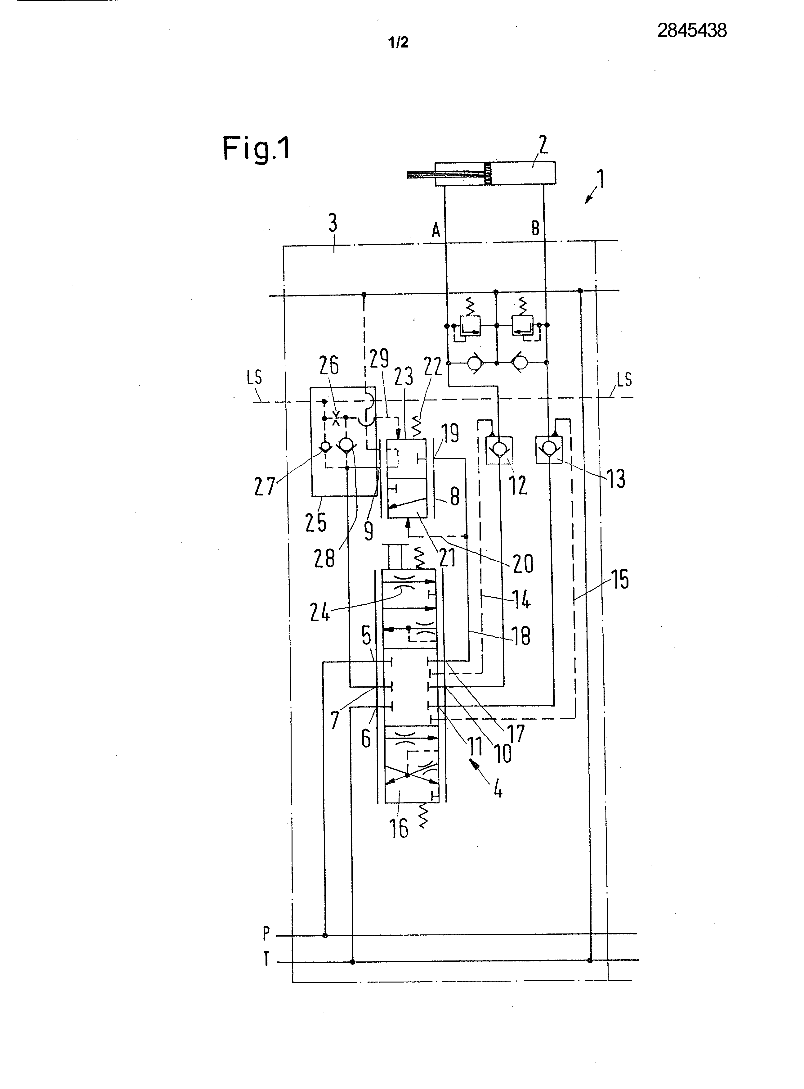
A hydraulic valve device comprising a power connection device, which has a high pressure connection and a low-pressure connection, a working connection, which has two working ports can be connected to a motor, a direction control valve which is arranged between the power connection device and the working connection, and a compensation valve, which, in a first driving direction, is loaded by a spring and by a pressure in a pressure chamber, which is connected to a load sensing line and, in a second actuating direction, which is opposite to the first actuating direction, is loaded by a pressure in the direction control valve. Such a valve device is known e.g. from DE 199,19 015 Al. There is a need for such a valve device to be able to control a motor. One such engine is to same, for example in the case of a working machine hydraulically actuated, raise or lower a load. In particular such a valve device may be used to control, in a power shovel, the hydraulic piston-cylinder devices, which are necessary for rectifying or for lowering an arm (arrow) of the excavator or to alter the inclination of the arm, to which is attached the bucket of the excavator, relative to the boom of the shovel. Using the direction control valve, is controlled the direction of the hydraulic fluid and in such a way that the liquid is received from the high-pressure connection is to a working connection is to the other working connection. The compensating valve serves to maintain a pressure difference as constant as possible on the direction control valve. The which poses problems in such a valve device are cases where the engine, which is supplied with hydraulic fluid via the working ports, is driven from the outside, for example when it is to lower a load or that the motor rotates a rotating frame of the excavator comprising a bracket arm. In particular in the latter case, due to the high inertia mass, it may happen that the motor need a great amount of fluid that can provide the valve device. The proportional valve is set to a certain flow rate value, for example 40 litres. The load, which is to be moved, potently is then pushed and starts to move, for example to rotate. Due to the inertia of the mass, the load may receive a sufficiently high kinetic energy to be in advance of the volume of entrained liquid, i.e. oil is no longer supplied in a sufficient amount. The mass becomes slower at a given time and interacts with a training effect, i.e. the motor acts as a pump. After a period of time, the mass moves sufficiently slowly so that the liquid is again sufficient and drives the motor. Thereby an oscillation occurs. Such tend to swing is undesirable. The aim of the invention is to reduce the tendency to oscillation. This problem is solved by a hydraulic valve device of the type indicated above, by the fact that the compensating valve comprises a device which acts on 1' opening. The compensating valve is thus no longer controlled exclusively and direct that high pressures in the load sensing line and in the direction control valve. Spacer is used in a manner, a device acting on the opening, which acts on the compensating valve and in particular a control opening movement in a predetermined manner. This prevents that the compensating valve is abruptly open, which could lead to the adverse conditions above. When the can be controlled in a targeted manner the opening movement of the compensating valve, is controlled then also correspondingly the movement, is driven by the motor which is connected to the working connections. With this control of movement of the load, can be reduced effectively in a relatively efficient manner the tendency to oscillate. Preferably the device that effects the opening produces a behavior-like opening ramp of the compensating valve. In other words the compensating valve is moved in time in such a way that there is an opening increasingly large and an amount of oil more and more is transferred. Stepped or abrupt An increase the amount of oil is surely avoided. The slope of the ramp depends on the pressures acting in the two operating directions of the compensating valve. When the difference in pressure is increased, the ramp is steeper, i.e. increasing the amount of oil, which flows through the valve, compensation, is stronger than in the case where, in the direction of actuation, the pressure difference on either side of the compensating valve is only lower. However, in any case it has been determined that 1' increasing the amount of liquid, which passes through the compensating valve, is controlled. Preferably, the device which effects the opening is arranged as a passive device. Therefore, provisions need not active command from outside, acting on the spool or on another element of the compensating valve. The device which acts on the opening operates on the contrary in a static manner, i.e. with immobile parts. This reduces the risk of errors. Preferably, the pressure chamber is connected to the pipe load detection by means of a throttle. The liquid, which is displaced out of the pressure chamber of the compensating valve, must pass through the throttle. The constriction limits the rate of outflow of the liquid from the pressure chamber. Therefore the speed of movement of the slide (or other valve element) of the compensating valve is simultaneously limited, which leads also automatically to the above-described influence on the opening. The constriction occurs therefore as device acting on the opening. Preferably, the compensating valve is arranged in the direction of flow between the power connection device and the working connection, downstream of the direction control valve. This arrangement has the advantage that the obtainable by a "sharing the flow", i.e. a distribution of the hydraulic fluid valve between multiple devices connected in parallel, which are supplied in common and power respectively independent motors, when the amount of power is not sufficient. The maximum load pressure, which appears in all the devices at valves, is sent to the compensating valve. Preferably, the compensating valve has an outlet, which is connected to a third input of the direction control valve, a first input of the direction control valve being connected to the high pressure connection and a second input of the direction control valve being connected to the low-pressure connection. The direction control valve can then function in the same manner in both directions for supplying the compensating valve. With individual control of direction takes place by means of the third input of the direction control valve. Preferably, between the outlet and the load sensing line is arranged a first non-return valve, which opens in Receiving Office Guidelines. is of the pipe load detection. With this first non-return valve a pressure, which is present at the output and is greater than the pressure in the line load detection, is transmitted to the load sensing line. Since the pipe load sensing controls a pump, which supplies the high-pressure connection, it this way, it is possible to signal to the pump pressure the actual need, when this need at the output is higher than in another part of the system. Conversely by means of the nonreturn valve, is prevented the actions of an increased pressure in the pipe load detection are applied to the third input of the direction control valve. Preferably, a second nonreturn valve is arranged between the output and a pipe section between the pressure chamber and the throttle. The second nonreturn valve is to allow the fast closing of the compensating valve when the pressure at the outlet increases too strongly. If using only the first non-return valve, the liquid, which returns the compensating valve in the closed position, should also pass through the throttle, which would result in optionally a certain deceleration during the closing process. Preferably the compensating valve has a spool, wherein the second non-return valve is arranged. This simplifies the structural arrangement. For the second nonreturn valve, no additional construction space is required. Other features and advantages of the present invention shall become apparent from the description given below taken with reference to the accompanying drawings, on which: -figure 1 represents a schematic view of a valve device; and -figure 2 represents a schematic cross-section of a compensating valve. A hydraulic valve device 1 to control a motor 2 which, in this case, is in the form of a piston and cylinder device, has a high-pressure connection P and a low pressure connection t. The high pressure connection P and the low-pressure connection T together form a power connection device, by means of which hydraulic fluid under pressure may flow, from a pump not shown, in the direction of the valve device 1 and return, therefrom, to a tank not shown in detail. The valve device 1 is in the form of a module 3, which can be joined by flanges to other modules. Therefore the power connection device can also be connected to the power connection device other modules. The valve device 1 also includes a device working connecting A, B, at which the engine 2 is connected. Between the power connection device P, T and the working connection A, B is arranged a direction control valve 4, which feeds liquid under pressure or the working connection A, or the working connection B, i.e. that it connects the working connection correspondent A, B the high pressure connection P. The control valve has three inputs. A first input 5 is connected to the high pressure connection. A second input 6 is connected to the low-pressure connection. A third input 7 is connected to a compensating valve 8, and more precisely at its output 9. The direction control valve 4 has a first output 10, which is connected to a working connection A, and a second output 11, which is connected to the other working connection B. In the lines between the outputs 10,11 and the operating connections A, B are arranged non-return valves 12,13, which can be controlled by auxiliary pipes 14,15 in the intermediary of a pipe 18 to an input 19 of the compensating valve 8. A control line 20, which opens into an end surface of the spool 21 of the compensating valve 8, branches off from the pipe line 18. On the opposite side, the drawer is loaded by a spring 22. The pressure in a pressure chamber 23, connected by a duct LS load detection, acts in the same direction. The drawer 21 is loaded therefore, in a first driving direction, by the force of the spring 22 and by the pressure prevailing in the pressure chamber 23. In the second driving direction, which is opposite to the first actuating direction, the pressure acts in the pipe 18, i.e. that the pressure at the pressure connection P is reduced by a pressure drop in a throttle 24 located in the drawer 16 of the direction control valve 4. The pressure chamber 23 is surely not directly connected to the pipeline LS load detection. At a device 25 which acts with the opening and that has a restriction 26 located in the conduit between the pressure chamber 23 and the pipe LS load detection. The output 9 of the compensating valve 8, which is connected to the third input 7 of the direction control valve 4, is connected via a first non-return valve 27 to the pipe LS load detection, the nonreturn valve 27 opening toward the tubular LS load detection. Furthermore, there is a second non-return valve 28 which connects the output 9 of the compensating valve 8 to a pipe section 29 between the pressure chamber 23 and the throttle 26. When then move the compensating valve 8 from the closed position represented of the drawer 21, wherein the outlet 9 is connected to the connection T of the tank, in its open position, in which the inlet 19 is connected to the output of the compensating valve 9, the opening movement is then influenced by the fact that the liquid, which is discharged from the pressure chamber 23, must pass through the restriction 26. Any other path is blocked by the non-return valves 27,28. The constriction 26 hence limiting the speed with which the drawer 21 of the compensating valve 8 is movable. But thereby the speed, with which the amount of liquid, which is fed to the motor 2, can increase, and is simultaneously also limited. This is valid especially in cases where the engine 2 is driven by means of an external load. Conversely, a rapid return of the drawer 21 in the closed position is possible because, in the case of an increase in the pressure at the outlet 9 of the compensating valve 8, corresponding to increase more rapidly the pressure in the pressure chamber 23 is possible via the second non-return valve 28. The valve device operates in principle as follows :' As the drawer 16 of the direction control valve 4 is moved, in both positions the high-pressure connection P is connected via the first inlet 5 to the third output 17 and therefore to the input 19 of the compensating valve 8. The compensating valve 8 is opened by the pipe 20. Thus a liquid can flow through the outlet 9 and the third input 7. The other direction of the liquid depends on the position of the drawer 16 of the direction control valve 4. When the drawer is lowered, the third input 7 is then connected to the first outlet 10 and therefore to the working connection A. The second input 6 is connected to the second input 11, i.e. that the working connection B is connected to the low-pressure connection t. As the drawer 16 is moved upward (relative to the representation of Figure 1), the conditions are reversed. In all cases, the nonreturn valve controlled 12,13 is controlled in the pipe, which is connected to the low-pressure connection t. The other respective nonreturn valve 13,12 is controlled by the pressure in the line to the working connection A, B. Figure 2 shows schematically the compensating valve 8 provided with the drawer 21, wherein the second non-return valve 28 is arranged. The compensating valve 8 includes a housing 30, wherein the drawer 21 is movable against the force of the spring 22. The pressure chamber 23, whose pressure acts also on the drawer 21, is connected by the throttle 26 to the connector load detection LS. LS The connector is connected directly, via the first non-return valve 27, to the output 9 of the compensating valve 8. The first non-return valve 27 is arranged in an insert 31, which is screwed into the housing 30. The size of the restriction 26 is a function of the special requirements, i.e. loads contemplated, that must be manipulated. In some cases, may also remove the second nonreturn valve 28 when, also during the closing movement, could be obtained a damping of the movement of the slide 21 of the compensation valve 8. A hydraulic valve system (1) has a supply connection arrangement having a high-pressure connection (P) and a low-pressure connection (T), a working connection arrangement, having two working connections (A, B) connectable with a motor (2), with a directional valve (4), which is arranged between the supply connection arrangement (P, T) and the working connection arrangement (A, B), and with a compensation valve (8), which is acted upon in a first operation direction by a spring (22) and a pressure in a pressure chamber (23), which is connected with a load-sensing line (LS), and in a second operation direction, which is opposite to the first operation direction, by a pressure at the directional valve (4). 1. Hydraulic Valve unit comprising a power connection device, which has a high pressure connection and a low-pressure connection, a working connection, which has two working ports can be connected to a motor, a direction control valve which is arranged between the * device for connecting power supply and the working connection, and a compensation valve, which, in a first driving direction, is loaded by a spring and by a pressure in a pressure chamber, which is connected to a load sensing line and, in a second actuating direction, which is opposite to the first actuating direction, is loaded by a pressure in the direction control valve, characterized in that the compensating valve (8) has a device (25) which acts on the opening. 2. Valve unit according to claim 1, characterized in that the device (25) which acts on the opening produces a behavior-like opening ramp of the compensating valve (8). 3. Valve unit according to either of claims 1 and 2, characterized in that the device (25) which acts on the opening is arranged as a passive device. 4. Valve unit according to any one of claims 1 to 3, characterized in that the pressure chamber (23) is connected to the pipe load detection (LS) via a throttle (26). 5. Valve unit according to any one of claims 1 to 4, characterized in that the compensating valve (8) is arranged, in the direction of flow, between the power connection device (P, T) and the working connection (A, B), downstream of the direction control valve (4). 6. Valve unit according to claim 5, characterized in that the compensating valve (8) has an outlet (9), which is connected to a third input (7) of the direction control valve (4), a first input (5) of the direction control valve (4) being connected to the high pressure connection (P) and a second input (6) of the direction control valve (4) being connected to the low-pressure connection (T). 7. Valve unit according to claim 6, characterized in that, between the outlet (9) and the pipe load detection (LS) is arranged a first non-return valve (27), which opens in the direction of the pipe load detection (LS). 8. Valve unit according to either of claims 6 and 7, characterized in that, between the outlet (9) and a pipe section (29) between the pressure chamber (23) and the throttle (25) is arranged a second nonreturn valve (28), which opens in the direction of the pressure chamber (23). 9. Valve unit according to claim 8, characterized in that the compensating valve (8) includes a drawer (21), wherein is arranged the second nonreturn valve (28). HYDRAULIC VALVE DEVICE
control function the position direction 4. the drawer 16 of the valve of A third 17 output is connected by