FASTENING HAS SWIVELLING ARM
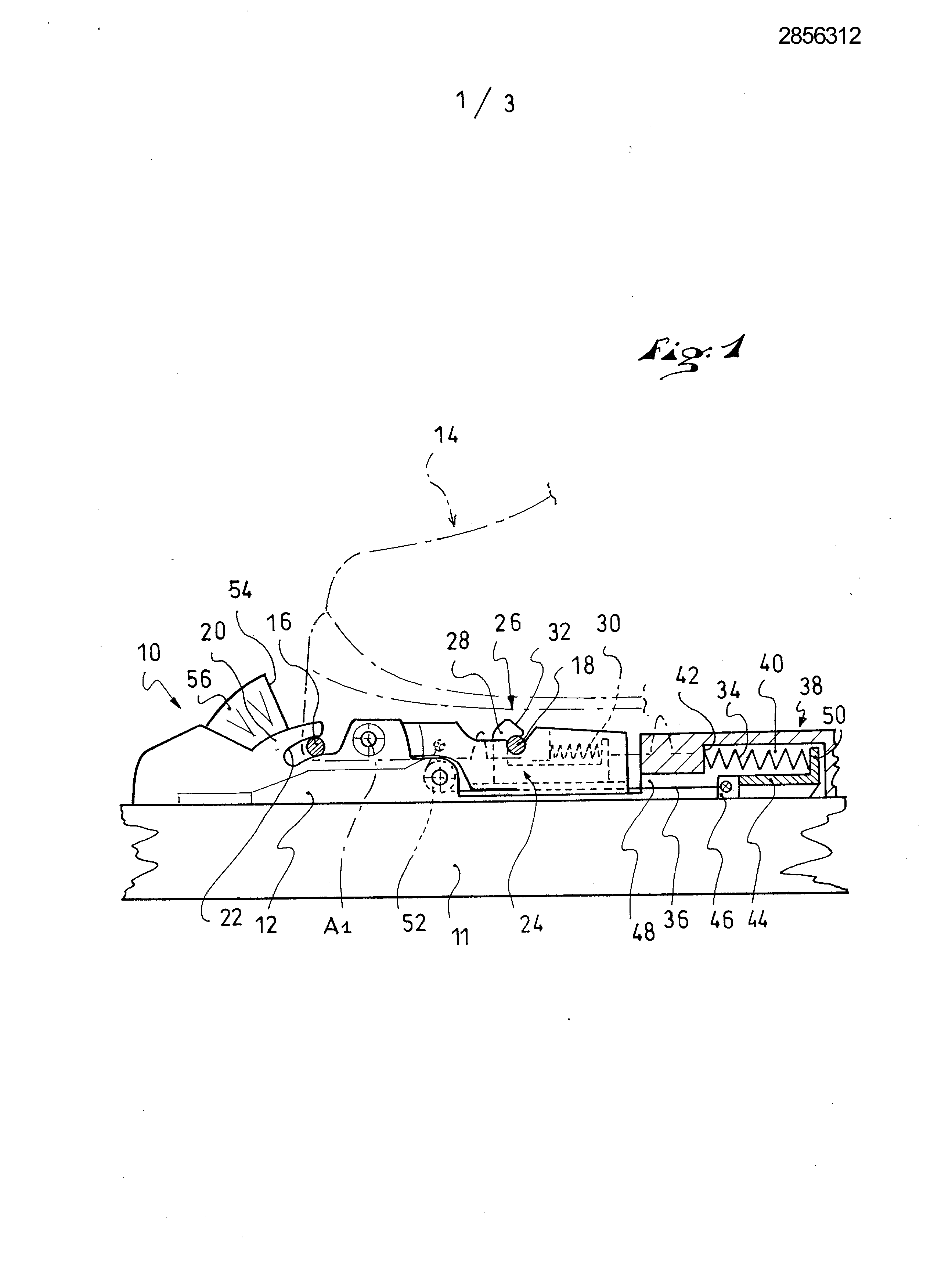
The invention relates to the field of devices for binding a boot to a sports article, of a type allowing lifting the heel of the shoe with respect to the sports article. Such fastening devices are used for example in the field of cross-country skiing, ski touring, Telemark of the ski, of the snowshoe, the ice skate or of the roller skate. In the field of cross-country ski, it is known devices in which the boot comprises, at its front end, a hinge pin which is received in a jaw of the fastener. The shoe, then, with respect to the gliding member to which it and coupled, a single rotation motion. The systems generally include a fixed elastic buffer collapse with which the front end of the boot when the heel is raised, so as to urge the shoe to a lowered position. Such a system is described for example in the document FR-2.650.192. Other systems have been proposed in which the shoe has a second bonding area to the fixing, in addition to the first front region of joint. The second zone is generally connected to a system for elastic return of the boot. FR-2.739.788 In the document, there is disclosed a device in which a fixed length link is articulated at one end on the second connecting area of the shoe (i.e. an axis) and on the other hand on a sliding carriage, which compresses a return spring. EP-1.106.218 In the document, the link is articulated at two fixed points but is of variable length, again to provide a reminder function. In either case, the link does not determine in any way the path of the shoe in relation to the connecting unit, which path is thus an arc of a circle around the connection area located at the front of the boot. FR-2.727.060 In the document, there is disclosed a fixation device with a flexible link whose one end is fixed, linked embedded in the base of the binding, and whose second end is hanging on a shaft arranged rearward of the forward end of the shoe. The front end of the shoe has a longitudinal groove cooperating with a complementary rib of the fixing to participate in the transverse guide of the boot relative to the binding. In the document WO-01/93 963, there is disclosed a system comprising a link of fixed length which is bonded at its two ends respectively to the base of the binding and a back strip of the shoe. The device includes a second link which is connected on the one hand to a slide of the base and on the other hand to a leading bar. The system has the drawback that they do not provide high torsional the shoe about a vertical axis. Indeed, upon such biasing (particularly present in not rotating or a skating in cross-country ski), the boot will cause a displacement of the sliding carriage to which is articulated the second link. The return force of the spring which acts on this carriage will be insufficient for reliable holding by torsion of the shoe. Furthermore, the system allows no retaining the front of the boot if the user is unbalanced to the rear, the front of the boot is free to lift. The invention, therefore, to provide a fastening device which, while being simple, reliable and inexpensive to manufacture, permits relative motion of the shoe with respect to the sports article which approximates of unwound natural motion of the foot while walking. For this purpose, the invention provides a device for binding a boot to a sports article raising the heel of the shoe with respect to the sports article, of the type in which the shoe comprises a first connection area arranged at the front of the boot and a second bonding area located behind the first bonding area, characterized in that the device comprises a gripping arm of fixed length which is articulated at two fixed points on a submount bonded to the sports article and on the other hand on the second area for connecting the boot, and in that the first area for connecting the boot is slidably guided on the device. Other features and advantages of the invention shall become apparent from the following detailed description, and in view of the accompanying drawings in which Figures 1 to 3 are schematic views in section in a vertical and longitudinal plane of a device according to the teachings of the invention, which is shown in three different positions. The invention will be described herein in an embodiment in which the fastening device is intended more particularly to the cross-country ski. The fastener 10 shown in Figures 1 and 2 has a base 12 which is intended to be fixed to a sports article 11, but which could also be directly integrated into the microprocessor. The base 12 could also be formed in multiple parts, or not certain of these parts being integrated into the sports article 11. According to the invention, the device is intended to secure a shoe comprising two connection regions. In the example shown, the shoe 14 has two anchoring elements 16,18 which are arranged in the sole of the shoe flush with below. 16.18 anchor members of this type are described in the patent application EP-A- [...] and EP-A- [...] which is usefully refer for more detail. Therefore, it is herein two webs cylindrical of revolution arranged across a longitudinal groove arranged in the underside of the sole. The leading bar 16 example situated at the front end of the sole and the back bar 18 is offset to the rear to be arranged at or in front of the shoe an area corresponding to the area of bending metatarsophalangeal of the user's foot. This arrangement of the connecting areas is especially preferred in cross-country ski because it allows, with a shoe sole flexible, maintain a bending of the shoe corresponding to that of the foot. However, the invention could be implemented with anchor members having another geometry. Each of the connecting members is therefore, with the corresponding portion of the groove of the sole, an exemplary embodiment of a connecting region of the shoe. The fastening device comprises first, to the front of the base 12, a fixed hook 20 22 which defines a channel open longitudinally at the top and/or the rear, and that is intended to receive the cylindrical bar 16 front of the shoe. The groove 22 has a height that is substantially identical to or slightly greater than the diameter of the web so that the web is received in the groove with a minimum clearance in the vertical direction. As shown in Figures, the groove 22 is not necessarily an elongated profile in a rectilinear path. Instead, in the example shown, the groove 22 has a curved profile dip forward and downward. Therefore, when the web 16 of the shoe moves longitudinally in the groove 22, is free to, it is vertically guided along a path determined by the profile of the groove. The hook 20 is provided above the upper face of the base 12. The hook is intended to be received in the longitudinal groove of the shoe such that, in a form-fitting manner, it participates in guiding the shoe in translation in a transverse direction (perpendicular to the plane of the Figures) and rotating according to a vertical axis. Therefore, the hook 20 is substantially the same width as the corresponding section of the groove of the shoe, and the groove 22 is through transversely in the two side faces of the hook 20. According to the invention, the fixing device 10 comprises a gripping arm 24 of fixed length which is articulated at two fixed points on the one hand on the base 12 and on the other hand on the second area for connecting the boot, in other words the tail bar 18. The arm 24 is articulated on the base 12, at its front end, about a transverse axis Al which is arranged in rear of the hook 20. The gripping arm 24 also has, on its rear portion, an automatic push bar 26 which is provided to receive the cylindrical bar rear 18 of the shoe. In this example, the automatic lock 26 includes a fixed jaw which is made up of a groove open at the top, and a movable jaw 28 sliding fitted with elastic recall means 30 for the towards the rear in its closed position shown in Figures. In this position, the two jaws define a housing of section corresponding to that of the back bar 18 of the shoe 14. The movable jaw 28 has an inclined ramp 32 which is arranged such that, with the bar 18 exerted on the ramp 32 a substantially vertical stress, from top to bottom, it pushes back forward the movable jaw 28 to an open position in which it allows access to the groove. When the bar 18 has entered the groove, the return means 30 of the movable jaw 28 return the latter to its closed position. The bar 18 is trapped and locked in the slot defined by the latch 26, while allowing for relative movement of rotation of the array 18 relative the latching arm 24, about the axis of the cylindrical bar 18. As shown in Figures, the latching arm is preferably received in the groove of the sole and its dimensions are preferably provided so that the arm also participates to the transverse guide of the shoe. In its lowered position shown in Figure 1, at rest, the latching arm is oriented substantially horizontally. In this position, it may be hooked the boot very simple on the device. For this purpose, it suffices to engage the web 16 of the shoe in the groove 22, then rotating around the leading bar, lower the shoe to lock the back bar 18 on the latching arm 24. Note that the latch 26 which receives the back strip of the shoe is arranged to the rear of the axis Al for articulating the arm 24 on the device 10. Once the shoe thereby locked, see that it is the latching arm 24 for controlling the relative motion of the shoe with respect to the articulated sports. With the arrangement of the invention, the back strip of the shoe described, when the user raises the heel of the boot with respect to the sports article, along an arc of a circle about the axis Al for articulating the arm 24 on the base. Indeed, once the tail bar 18 locked to the arm 24, it remains at a constant distance from the axis Al. During this movement perfectly determined of the back bar 18, i.e. an area of the shoe that substantially corresponds to the ball of the foot of the user, the leading bar 16 is longitudinally free and moves in the groove 22, in this case forwardly thereof. While moving longitudinally, the leading bar is perfectly guided along a path defined by the profile of the groove 22. In the example shown, the groove 22 controls a downward movement of the leading bar 16 when the heel of the shoe is raised. The insertion movement is particularly sensitive at the end of movement. Kinematic The total device according to the invention is thus mainly given by the locking arm 24, but it is also influenced by the geometry of the guide groove 22. This may have a profile different from that illustrated herein. Furthermore, we can see that, when the shoe is in the lower position as illustrated in Figure 1, the front end of the shoe is prevented from lifting vertically upwards, by the leading bar which is blocked according to this direction in the groove 22. The fastening device 10 also includes an elastic return system the connection arm 14 to its lower position. Advantageously, the elastic return system comprises at least one elastic member 34 which is connected to the sports article 11, and a flexible link 36 that connects the elastic member 34 the latching arm 24 and which cooperates with at least one return member 52. In the example shown, the fastening device 10 includes a guide edge 38 which is formed of a profile parallelepiped cross section and extending longitudinally toward the rear, back the connection arm 24. In a known manner, this guide edge 38 is provided to cooperate with the groove of complementary section provided in the sole of the footwear to provide a lateral guidance of the footwear assembly/fixing. The guide edge 38 thus increases rearwardly the hook 20 and the latching arm 24. Advantageously, the elastic member 34 is integrated within a housing 40 that edge 38. In the example shown, the elastic member 34 is a compression spring which is disposed horizontally and longitudinally within the housing 40. The front end of the spring 34 rests against a front face 42 of the housing 40. The front end of the spring is therefore fixed. The rear end of the spring rests on a movable carriage 44 which can slide longitudinally with respect to the base 12 and to the edge 38. More specifically, the carriage 44 has a front end 46 which moves at a front opening 48 of the housing 40, and a rear end 50 that moves in the housing 40 and on which is supported the rear end of the spring 34. Such an arrangement of an elastic member and a movable carriage is similar to that found in the device described in the document EP-768.103 and in some of the devices cross country ski bindings being marketed by the applicant is aware. However, instead of the prior art, in which the elastic member is connected to the boot by a link, the device represented comprises a flexible link 36 that connects the elastic member 34 the latching arm 24. As shown in Figures, the link 36 is not directly hooked to the elastic member 34 but on the front end of the carriage 44 46. It passes over a deflection 52 which is comprised of a pulley mounted on the base. Referral 52 could also be formed by a simple sliding surface, preferably curved. The other end of the flexible link 36 is hooked on the latching arm 24 such that the portion of the flexible link 36 which extends between the return 52 and the latching arm 24 is substantially vertical, so that the return force exerted on the latching arm 24 is mainly downwardly directed, including when the latter is high position as shown in Figure 3. Instead, the portion of the link 36 from the return 52 to the elastic member 34 extends along a substantially horizontal direction. As shown to the figure, when the latching arm 24 moves from its lower position to its upper position, the flexible linkage 36 pulls the movable carriage 44 forward and causes the compression of the spring 34, which provides a return force which tends to return the shoe to a horizontal position with respect to the sports article. Preferably, the flexible tie is substantially inextensible. It can for example be a wire cable or a fibre rope very low extensibility, for example a fibre rope aramid. May also be contemplated that the link is in the form of a strip. The pull strip is produced, for example in the form of a metal strip, or a bundle of parallel fibers embedded in a polymeric material. Preferably, the link is sufficiently soft and flexible to not provide significant spring, and especially for supporting a bell crank angle of about 90 degrees. A Figure 2 is shown a raised intermediate position of the shoe in which the front part of the sole of the shoe contacts a bearing surface 54. this support surface 54 is preferably elastic and is formed, for example, as a buffer 56 mounted to the front of the base 12. The bearing surface 54 to order to introduce an index member by which the user can "recognize" or "feel" a reference position. If the user continues traveling motion of the heel as shown in Figure 3, this movement will be by compressing the elastic buffer 56. The reference position is ascertained by a bearing surface 54 connected to the base 12, thus to the sports article 11, and on which bears the front end of the sole of the shoe. However, this support surface 54 could cooperate with another portion of the shoe. Predicted that the reference surface is formed as a small elastic buffer arranged at the leading end of the groove 22. In this case, it it will cooperate with the leading bar 16. Furthermore, the support surface 54 shown in Figures is fixed, but would be anticipated that its longitudinal position is adjustable by the user, in particular for that it can adapt the reference position to the length of its stride. In the example shown, the, between the intermediate position of Figure 2 and the extreme position of Figure 3, the resilient pad provides a restoring force complementary to that of the main return device which is formed by the spring 34 and the flexible linkage 36 For decoupling the shoe of the device according to the invention, it is possible for example to provide a pull tab (not shown) is bonded to the movable jaw 28 to urge it forward against the spring 30, to cause the unlocking of the bolt 26. Therefore, is in a first time will allow the release of the back bar 18, vertically upwards, and in a second period the release of the leading bar 16, longitudinally rearwardly and/or upwardly. Therefore, it is possible to provide a clamping device, the construction is particularly simple ergonomic but that controls a movement of the shoe with respect to the sports article, said movement being towards the natural motion of lifting of the foot. The device has a fastening arm (24) of fixed length articulated in two points. A shoe (14) includes anchorage units (16,18) that is arranged at front of the shoe and situated in back of the unit (16), respectively. The arm is fixed on a base plate (A1) that is connected to sports good and on the unit (18). The unit (16) is slidingly guided on a hook and a groove of the device. 1. Device for binding a boot to a sports article raising the heel of the shoe (14) with respect to the sports article (11), of the type in which the shoe comprises a first connection area (16) arranged at the front of the boot and a second connection region (18) located behind the first bonding area, characterized in that the device comprises a gripping arm (24) of fixed length which is articulated at two fixed points on the one hand on a base (12, Al) related to the sports article (11) and on the other hand on the second bonding area (18) of the shoe (14), and in that the first binding region (16) of the shoe is slidably guided (20,22) on the device. 2. Device according to claim 1, characterized in that the articulation point (18) of the arm (24) on the shoe (14) is arranged in rear of the point of hinging (Al) of the arm (24) on the fixture (12). 3. Device according to claim 2, characterized in that the articulation point (18) of the arm (24) to the fastening device (12) is arranged longitudinally between the two connecting zones (16.18) of the shoe (24). 4. Device according to any one of the preceding claims, characterized in that the arm of fixed length (24) is hinged to the shoe by a releasable mechanism (26). 5. Device according to any one of the preceding claims, characterized in that the arm (24) is returned elastically to a lowered position. 6. Device according to any one of the preceding claims, characterized in that the first binding region (16) of the shoe (14) is guided (20,22) transversely and vertically but is free longitudinally relative to the device (12). 7. Device according to any one of the preceding claims, characterized in that the second bonding area (18) of the boot comprises a cylindrical axis transverse hinge hooked under the sole of the boot. 8. Device according to any one of the preceding claims, characterized in that the first binding region of the shoe comprises a transverse bar (18) which is hooked under the sole of the boot and which is received in a guide groove (22) of the device. 9. Device according to claim 8, characterized in that the guide groove (22) is open at one of its longitudinal ends for the purpose of drawing the leading bar (16). Fastening device cleanup