DEVICE OF MEASURE OF LOCATION PER HALL EFFECT
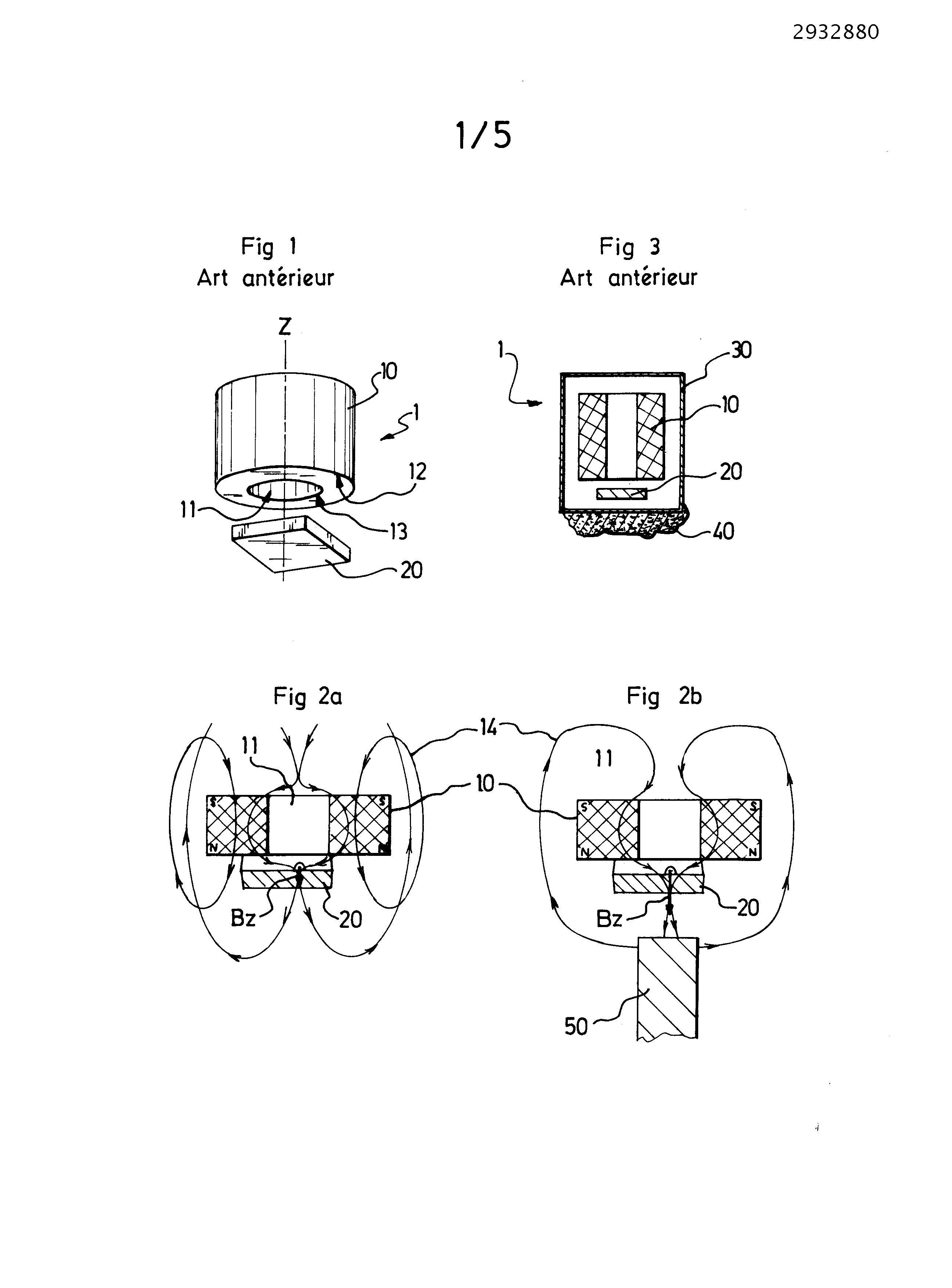
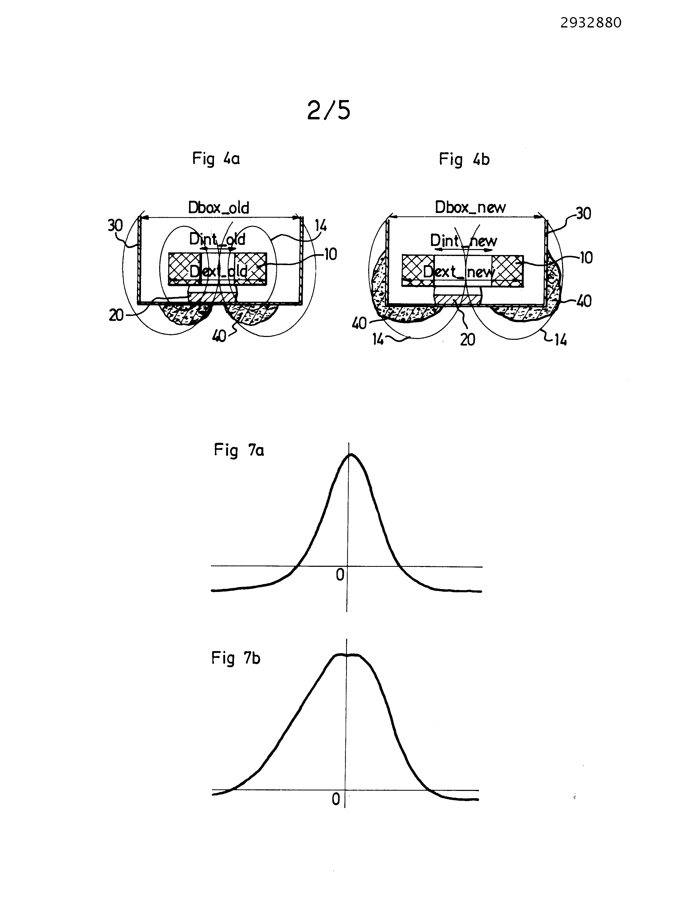
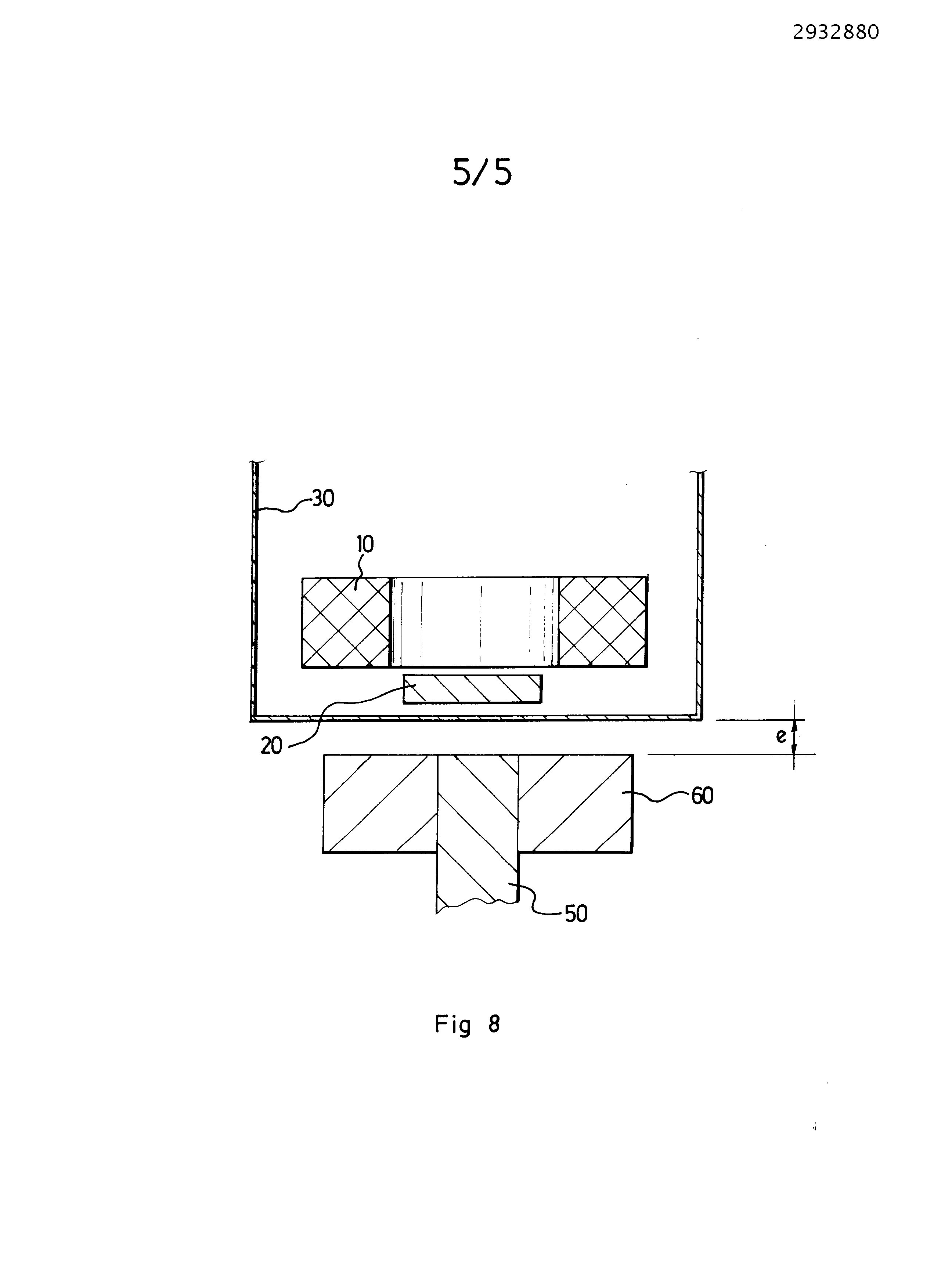
The present invention relates to a position measuring device by Hall effect. Conventionally, such a device includes a housing, and a Hall effect sensor, positioned in said housing. The sensor typically comprises a magnet and a chip. The chip is integral with the magnet, and the magnet-generally substantially cylindrical-is vented, such that it comprises an outer perimeter and an inner perimeter. Such a measuring device is used in particular in the motor vehicle transmission, for example, to determine the position of the gear selector. Typically, a shift lever is connected to the transmission via a lever system, so that the movements thereof, lead to a translation and rotation of a selector shaft speed ratios. In general, the sets and tolerances in the linkage cause the the sensor is placed preferably at the axis of gear selection rather than at the shift lever. The position "dead center" of the gearbox corresponds to a generally central position; and the function of the sensor is to determine the position of a target on the selector shaft speeds and thereby determining whether the control of the transmission is in "dead center". However, a transmission comprises gears that wear out and release the iron filings in the oil. Or, as the sensor includes a magnet, it attracts the swarf present in the oil and the swarf starts to agglutinate beneath the sensor (due to the direction of magnetization), thereby corrupting the measurement or are destroyed. To reduce the amount of swarf present in the oil, it is known to position one or more magnets at the bottom of the enclosure for recovering the same and prevent it does not fixed under the sensor. Such a solution represents an additional cost and does not allow recover all fillings due to the limited "range" magnets. The present invention aims at remedying these drawbacks by proposing a solution requires no additional magnet. With this purpose to, the device according to the invention, mentioned further according to the preamble above, is essentially characterized in that the inner circumference is maximum, relative to the space available in the housing. Thanks to this feature, the swarf In one embodiment, the outer perimeter is maximum, relative to the mechanical stresses of the magnet. Thanks to this feature, the iron filings is not drawn on the face of the chip, therefore it does not disturbing the measurement. Maximum The outer perimeter also provides an inner perimeter while maintaining maximum mechanical stresses. In one embodiment, the outer perimeter and/or the inner perimeter comprises at least one flat. In one embodiment, the outer perimeter and/or the inner perimeter are cylindrical. In one embodiment, the ratio between the outer perimeter and the inner perimeter is 2:1. Preferably, the ratio between the outer perimeter and the inner perimeter is such that the thickness of the ring of the magnet is mechanically feasible, i.e. that it can comply with the mechanical stresses use. Specifically the minimum thickness of the crown of the magnet (when the is substantially a hollow cylinder) is preferably at least equal to 2 mm. In one embodiment, the inner surface of the magnet (the hole) is greater than or equal to the surface of the chip. In one embodiment, the outer diameter is 10 mm and the inner diameter is 5 mm. In one embodiment, the device according to the invention further comprises a ferromagnetic target, and the target is surrounded by a non-ferromagnetic. When the ferromagnetic target comes close to the sensor, it is magnetized by reaction. Therefore fillings can binding to the target. With the non-ferromagnetic, the swarf is less prone to binding to the target; in particular as a function of its thickness. Furthermore, the non-ferromagnetic also advantageously a mechanical effect scanning when the target and the sensor have a relative movement, which is provided for scanning the swarf optionally consolidated beneath the sensor. The shape of the non-ferromagnetic member is preferably adapted to the relative movement of the target and the sensor, in the species a planar face for translational movement and a curved face for rotational movement. Preferably, the non-ferromagnetic is arranged nearest to the sensor, i.e. closest to the chip, the sensitive surface of the sensor. In one embodiment, the non-ferromagnetic member is made of plastic, typically a plastic cap fitted on the target. In an advantageous embodiment, the chip is offset, in the species disposed above, relative to the point of zero Gauss of the magnet. Other features and advantages of the present invention will appear more clearly upon reading of the following description of exemplary and non-limiting illustrative example and made with reference to the drawings appended in which: -figure 1 illustrates a Hall sensor according to the prior art, figure 2A illustrates the principle of operation of a Hall measurement device in the absence of ferromagnetic target, figure 2B illustrates the principle of operation of a Hall measurement device in the presence of a ferromagnetic target, figure 3 illustrates in cross-section the agglutination of swarf under a sensor, figure 4A also shown in cross-section the agglutination of swarf in a sensor according to the prior art, figure 4B shown in cross-section the agglutination of swarf about a sensor according to the invention, figure 5A illustrates the variation in a field of a magnet according to a translation and rotation of a target relative to said magnet, according to the prior art by the absence of swarf, figure 5B illustrates the variation in a field of a magnet according to a translation and rotation of a target relative to said magnet, according to the prior art in the presence of swarf, figure 6A illustrates the variation in a field of a magnet according to a translation and rotation of a target relative to said magnet, according to the invention in the absence of swarf, figure 6B illustrates the variation in a field of a magnet according to a translation and rotation of a target relative to said magnet, according to the presence of swarf, a Figure 7 illustrates the variation in a field of a magnet based on a translation of a target relative to said magnet, according to the prior art by the absence of swarf, figure 7B illustrates the variation in a field of a magnet based on a translation of a target relative to said magnet, according to the prior art by figure 8 shows an embodiment of the device according to the invention. A sensor 1 conventional Hall implemented in the invention is illustrated in figure 1. It comprises a magnet 10 and a chip 20 integral with the magnet, configured to measure the magnetic field of the magnet 10, particularly its vertical component Bz, as illustrated in figure 2A figure 2B and in which the magnet 10 is configured example with the south face S at the top and the north face N down. The chip 20 is preferably positioned in front of the hole 11, the hole 11 representing the sensitive region of the sensor 1. The magnet 10 is vented. The magnet 10 thus comprises an outer perimeter and an inner perimeter 13 12. Preferably the hole 11 of the magnet is circular. In the illustrated embodiment, the magnet is rotationally symmetrical about a Z-axis (vertical), so that its outer perimeter 12 and its inner perimeter 13 are circular and concentric. The figure 2A illustrates the principle of operation of a Hall measurement device not comprising ferromagnetic target. The figure 2B illustrates the principle of operation of a Hall measurement device comprising a ferromagnetic target 50. By comparison of these two Figures, the field lines of the magnet 14 are clearly deflected by the presence of the target 50. Bz The component of the magnetic field of the magnet 10 is modified and measured by the chip 20. As shown Figure 3, the sensor is positioned in a housing 30. Figure 3 also illustrates the problem of the present invention, in other words the swarf consolidated 40 in the housing 30. Or, as described previously, the presence of swarf can be highly disturbing the field lines, and measuring. To this end, according to the invention, at least one of the outer and inner perimeter 13 is maximum. As shown figure 4A, if the inner perimeter 13 is too low, the swarf is fixed on the face of the chip 20, on the sensitive zone, and risk from disturbing the measurement. However, by maximizing the inner perimeter, i.e. the diameter in the species, the swarf is retained out of the sensitive area. The influence of the outer perimeter is illustrated in figure 4B: the rise thereof also offsets the field lines 14 to the exterior of the sensor. Therefore, the swarf is attracted to the outside, the sides, of the housing 30. Therefore, while for economical reasons have a tendency to reduce the size of a magnet, surprisingly according to the invention, is suitable for opposite maximize the inner and outer perimeters. The thickness of the magnet between its inner and outer perimeters must meet mechanical stresses of use of the sensor, at least 2 mm in the species. The outer perimeter 12 is limited by the size of the housing 30 and passage of the connections of the chip 20. The shape of the outer and/or inner perimeters may be circular or ovoid shape. It can also advantageously contain flats. To illustrate the principle of the invention, may be defined according to the prior art (figure 4A) a cylindrical magnet perforated, and of which the bore is also cylindrical and concentric. The cylindrical magnet 10 has an outer diameter and an inner diameter Dint_old Dext_old ; and is inserted into a housing 30 which the external dimensions are limited by a diameter Dbox_old. According to the invention, for the same external dimensions housing limited by a diameter equal to Dbox_new Dbox_old , then the dimensions of the magnet 10 are such that the outer diameter is greater than the diameter Dext_new Dext_old Dint_new and the inner diameter is greater than the diameter Dint_old. One skilled in the art easily transposing the above principle to other forms of the magnet than cylindrical. Comparative measurements between one embodiment of the device according to the invention and the prior art have been made and are illustrated in Figures 5A, 5Β , 6A and 6B. Each figures 5Α , 5Β , and illustrates the measuring 6A 6B B (mT) of the field of a magnet according to a translation and rotation X (mm) R (°) of the same target relative to said magnet, for a housing of similar dimensions. Figures 5A and 5B illustrate the results of the use of a device (that is say a magnet), according to the prior art, typically a circular magnet 7 mm outer diameter and inner diameter 3 mm, in which Figure 5A is the sensor response in "normal" configuration (without swarf), and Figure 5B is the response of the sensor in the presence of swarf, particularly 0.2 to 0,3g of swarf. Figures 5A and 5B, it is clearly shown that the presence of swarf clips and spreads the measurement signal, which makes the sensor ineffective. Figures 6A and 6B illustrate a device, i.e. a magnet, according to the invention typically a circular magnet 10 mm outer diameter and inner diameter 5 mm, in which Figure 6A is the sensor response in "normal" configuration (without swarf), and Figure 6B is the response of the sensor in the presence of swarf, in the species 2 to 3g of swarf. Figures 6A and 6B, it is clearly shown that the device according to the invention allows limiting the impact of the presence of swarf: it does not substantially modified the response of the sensor. In the comparison between the prior art (figure 5B) and the invention (figure 6B), note is that the invention provides reliable results with a mass of swarf substantially ten times greater. Furthermore, in this type of devices according to the invention, there is a point Gauss said zero point of the magnet, to which all components (Bx, By, Bz) of the magnetic field of the magnet are zero. The advantage of this zero point Gauss is that it is relatively stable over time and relatively independent of the temperature. In order to measure position, as seen previously, is arranged generally a ferromagnetic piece 50, said target, in front of the housing 30. In operation, the target 50 and the housing 30 are driven by a relative movement, and the sensor 1 is configured to measure the range of this movement, i.e. the relative position of the target and the sensor. Upon displacement of the target 50, the field of the magnet 10 is deflected, attracted by the same, and there is a large field variation when the target 50 moves opposite the latter. Furthermore, for reducing interference of the measurement, it is known an initial positioning of the sensor chip Hall Gauss zero point (before the presence of the target, the position of zero Gauss is deflected in the presence of the target). Figure 7 A may correspond for example to a projection of the figure 5A on a given dimension, and corresponds to a device implemented without swarf. Based on the displacement of the target, the measurement signal of the intensity of the magnetic field is substantially in the form of a Gaussian: first negative and relatively constant, positive and increasing and on a maximum when the target and the sensor are aligned. After the maximum, the signal becomes positive decreasing, and then negative and relatively constant. The figure 7B may correspond for example to a projection of the figure 5B on a given dimension, and corresponds to the arrangement for the results illustrated in Figure 7A in the presence of swarf, to the same scale. The presence of swarf has the effect of widening the Gaussian-thus disturbing the mesureet shift the signal to positive values, thereby consequences of increasing the value of the maximum, and above all to increase display the value of the minimum. Or the greater the value of the minimum approaches zero, more the risk that the sensor in the switch mode does not switch (at zero crossing) is large. According to the invention, contrary to the prior art, is positioned advantageously the target initially 50 offset, in the species disposed a few tenths of a millimeter above, relative to the point of zero Gauss of the magnet 10. With this configuration, it is possible to reduce the level of magnetic field on the sensitive surface on the face of the chip 20, thereby reducing the attractiveness of the sensor 1 to the swarf. Furthermore, such a configuration can provide magnetic offset, thus a response of the sensor 1 in a zone of impacted by swarf. The being particularly advantageous in a mode of operation (defined by the shape of the target 50) type switch ("switch") of the sensor 1. In another embodiment of the invention, it is still possible to improve immunity to the swarf clear of the sensor 1 by placing a patch nonferromagnétique 60 around the target 50 (Figure 8). With this configuration, the swarf 40 does not bind on the rod 50. Furthermore, this configuration accomplishes cleaning of the sensitive surface of the sensor 1. This is all the more effective that the measuring chamber e (or space between the underside of the housing 30 and the upper face of the target 50, commonly called " airgap ") is low. Upon displacement of the target, the non-ferromagnetic portion 60 carries away the swarf on the sides of the sensor, 20 away from the chip. The invention relates to a device for measuring a position using the Hall effect, which comprises: a casing (30) and a Hall-effect sensor (1), comprising a cylindrical magnet (10) and a chip (20), in which: the chip (20) is fastened to the magnet (10); the magnet (10) has a hole (11) right through it along an axis perpendicular to its bases, and includes an outer perimeter (12) and an inner perimeter (13), the sensor (1) being positioned in said casing (30). According to the invention, the device is noteworthy in that: the inner perimeter (13) is maximized relative to the mechanical stresses of the magnet (10); and the surface area of the hole (11) is equal to or greater than the surface area of the chip (20), so as to circumvent the presence of iron filings on the face of the chip (20). 1. The position measuring device by Hall effect comprising: a housing (30), a Hall sensor (1), having a cylindrical magnet (10) and a chip (20), wherein: the chip (20) is integral with the magnet (10), the magnet (10) is perforated (11), and comprises an outer perimeter (12) and an inner perimeter (13), the sensor (1) is positioned in said housing (30), characterized in that the inner circumference (13) is maximized relative to the available space in the housing (30) so as to circumvent the presence of iron filings on the face of the chip (20). 2. Device according to claim 1, wherein the surface of the hole (11) is greater than or equal to the surface of the chip (20). 3. Device according to claim 1 or claim 2, wherein the outer perimeter (12) is maximized relative to the mechanical stresses of the magnet (10). 4. Device according to any one of the preceding claims, wherein the outer perimeter (12) and/or the inner perimeter (13) comprises at least one flat. 5. Device according to claim 4, wherein the ratio between the outer periphery (12) and the inner perimeter (13) is 2:1. 6. Device according to any one of the preceding claims, further comprising a ferromagnetic target (50), wherein the target (50) is surrounded by a non-ferromagnetic (60) mechanical sweeping powder consolidated in the sensor. 7. Device according to claim 6, wherein the non-ferromagnetic element (60) is disposed closest to the chip (20). 8. Device according to any one of claims 6 or 7, wherein the non-ferromagnetic element (60) is made of plastic. 9. Device according to one of claims 6 to 8, wherein the shape of the non-ferromagnetic element (60) is adapted to the relative movement of the target (50) and the Hall sensor (1). 10. Device according to any one of the preceding claims, wherein the chip (20) is offset from the zero point Gauss of the magnet (10).