METHOD AND APPARATUS FOR MANUFACTURING COMPOSITE SHEET
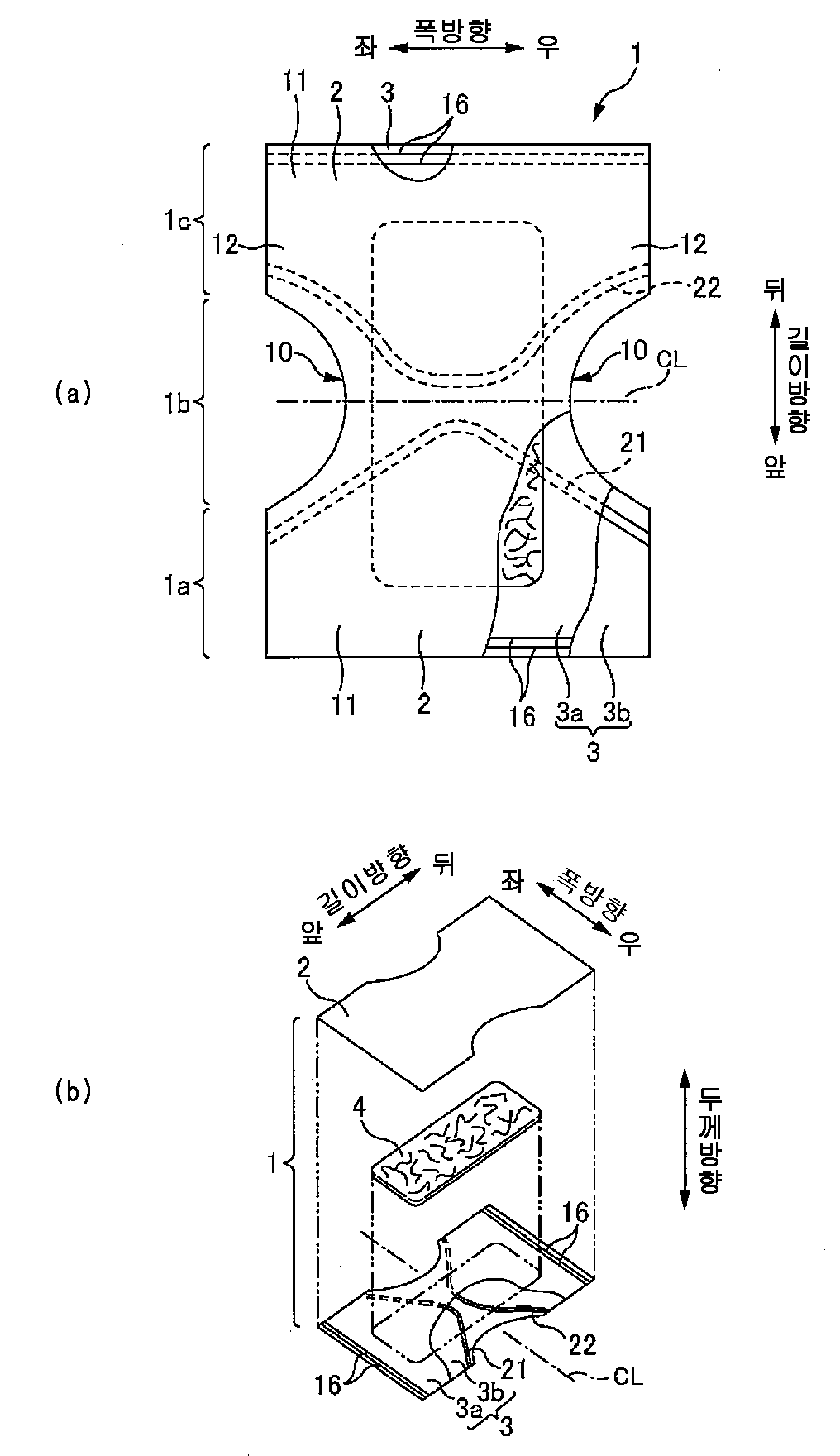
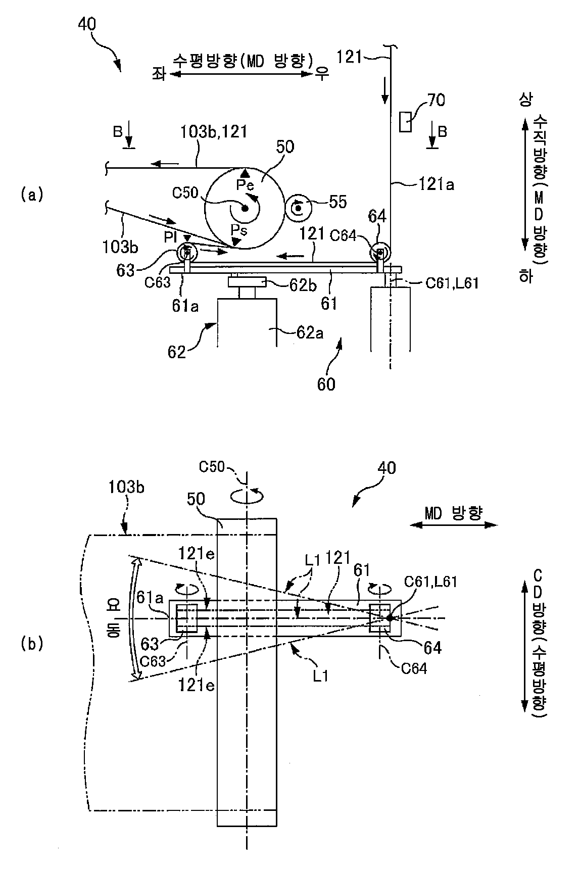
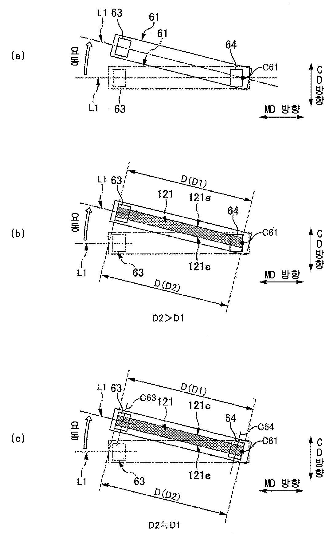
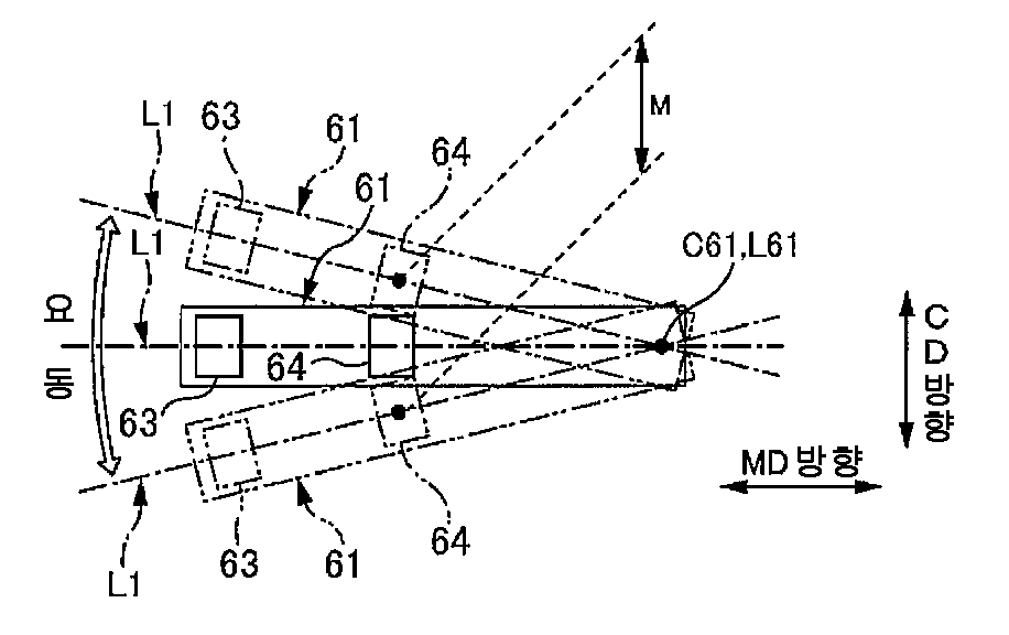
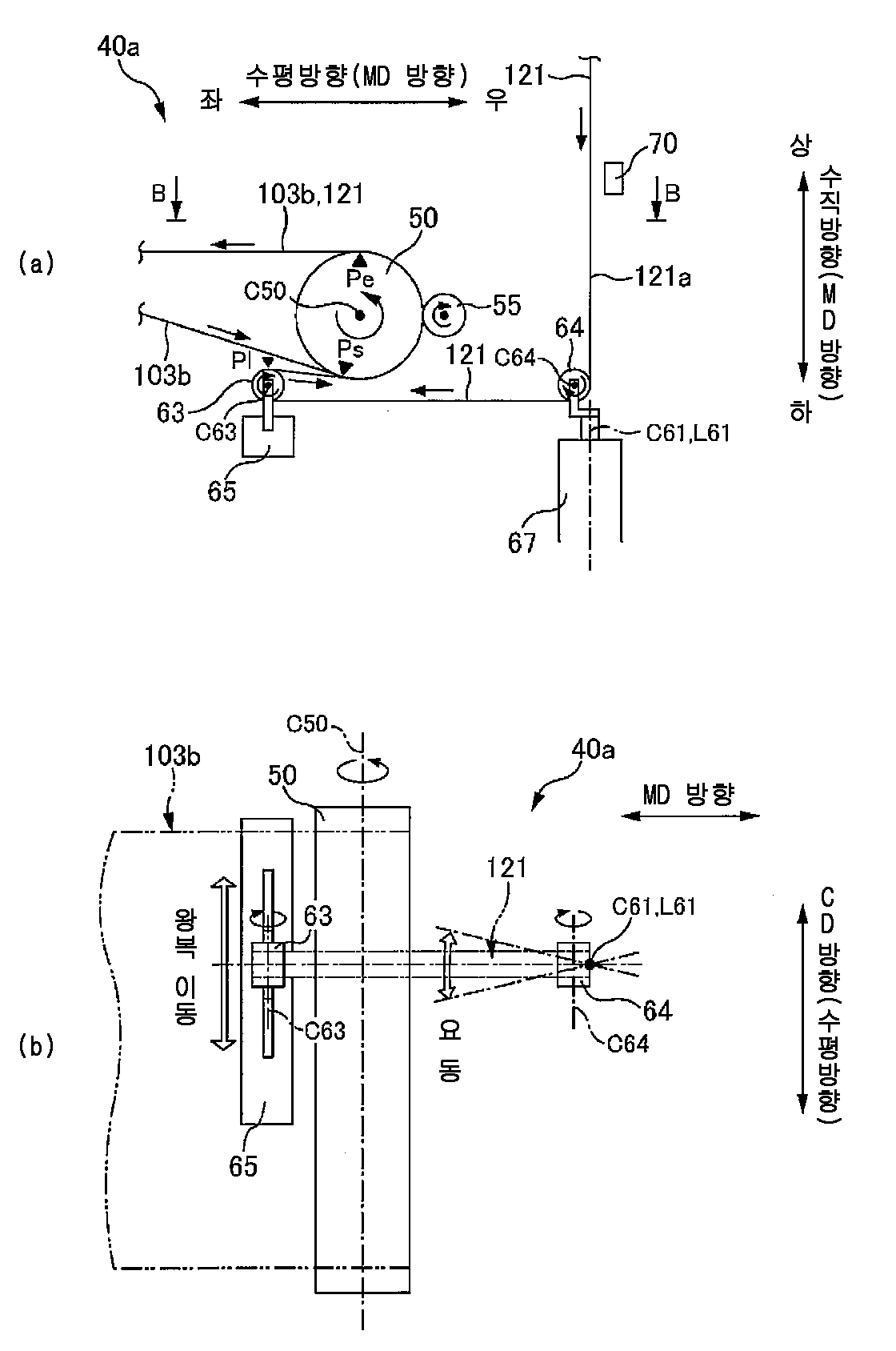
The present invention refers to, stretching in the conveyance direction to massively elastic sheet shaped a coordinate defined meandering pattern in which reciprocations in the bonded composite for producing sheets of relates to device and method. Conventional, of an absorbent article such as a disposable diaper are in manufacturing line, stretching in the conveyance direction being carried continuously shaped surface structure of battery, sine curve such as sequentially elastic material as a meandering pattern in which reciprocations in the attached. a. As method thereof, the patent document 1, shaped sheet at the intersection to a carrying direction of a rocking directions transfer path sheet shaped arm while located in close proximity to, said rocking arm rocking stage of through holes by passing elastic member, as to be pivotable relative to sheet shaped elastic member attaching the. is disclosed. Yet, the patent document 2, transfer roll outer envelope elastic member roller rotary power to the rotary turning the channel opens, said rotation rollers said transfer roll axis direction by moving the reciprocating, transfer roll the outer periphery of the surface member such as a sinusoidal curve the sucking and holding pattern meandering, then, transfer the outer turn of a roll of a cell by contacting the sheet shaped peripheral surface shaped elastic member attached to a pack by delivering to the sheet is disclosure. However, as the aforementioned elastic member, : after forming a to massively a width, said patent document 1 in method of, rocking of said through hole passage of discarded during recording, deletion, and elastic member are folded over, as a result, said elastic member placed in a sheet shaped attached by. it is difficult to obtain a. While, according to method of patent document 2, of a rotary roller by means of outer peripheral surface since the conclusion of adjusts a member, elastic member planarizing state transfer in the transferring roll, as a result, placed in a sheet shaped elastic member can be attached by. Stage, of a rotary roller by means of movable operating by reciprocating, rotary roller at member releasing of automatic transmission. so there is a threat that the not to be taken off the is unstable. Consequently, on sheet shaped attachment to target locations, as well as the human detect time accuracy, the worst-case, away from rotary roller elastic member is off. And, such the risks, in particular elastic member as adds the soft material mixed, which processing performance to a high speed rotary roller that moves when 2000. Also, transfer roll outer periphery of the elastic member with a brake, said meandering pattern in which reciprocations in the since the to cause history by, elastic member rigidly an atomic said outer peripheral surface in a collapse meandering pattern in which reciprocations in the coverage but if, in this regard the, breathable mixed elastic member is to reduce the possibility of adsorption when the material is not required, with flip-flop of semiconductor memory adsorption now the active retaining means also to provide a two-dimensional not. I.e., transfer roll outer periphery of a meandering member surface stably maintain the pattern. it is difficult. The present invention refers to, of the existing method such as said it is insulating layer, defined stretching in the conveyance direction being carried continuously provided to the mobile terminal structure of battery shaped, elastic belt absence a routed not directly applied to said roller as a second cross the conveying direction and by moving the reciprocating, said to massively defined meandering pattern adhered sheet composite for producing sheets of in device and method, transfer roll of omiting reduction ratio, said roller in a boss traveling state which can attain of stabilizing of the composite sheet to provide a manufacturing method and manufacturing device, intended for. The callee opens the folder of his said notable invention, Defined stretching in the conveyance direction being carried continuously provided to the mobile terminal structure of battery shaped, elastic to massively said cross the conveying direction and as a second continuous for reciprocally moving by the source region of the first, said seat surface in said electrode a boss said-period as a second structure of battery while said shaped to massively said composite surface as method for producing sheets of, Said shaped sheet, said which rotate along a carrying direction for joining the outer turn of a roll of supply peripheral surface, said outer peripheral surface of roll for junction said contact portion of said shaped sheet, said devices through the predetermined guide member the to massively said to overlap to massively by said portion, said shaped structure of battery to massively said fixes surface and bonded, Said guide member, said cylinder, a displacer also reciprocatingly moves as a second roller and the moving shaft, said defined are disposed at positions has a roller supplied belt absence , Said to massively, sequentially said supply roller and outer peripheral surface of said cylinder, a displacer also reciprocatingly moves roller outer periphery of said rotating inside the reservoir the channel opens surface inducing sheet shaped, According to the operation in reciprocation of the roller cylinder, a displacer also reciprocatingly moves said supply roller outer periphery of said cylinder, a displacer also reciprocatingly moves roller facing to said surface, said supply roller oscillate the manufacturing method of the composite sheet is characterized by. Yet, Defined stretching in the conveyance direction being carried continuously provided to the mobile terminal structure of battery shaped, elastic to massively said cross the conveying direction and as a second continuous for reciprocally moving by the source region of the first, said seat surface in said electrode a boss said-period as a second structure of battery while said shaped to massively said composite surface as device for producing sheets of, Said be configured to rotate in a direction along the conveyance direction said outer peripheral surface said rolls and for joining can, for example, be a sheet shaped, for joining said contact peripheral surface the outer turn of a roll of said shaped sheet portion of the to massively said to overlap to massively said by said portion, said shaped structure of battery surface to massively said fixes bonded a guide comprising a member which is, Said guide member, said cylinder, a displacer also reciprocatingly moves as a second roller and the moving shaft, said defined are disposed at positions has a roller supplied belt absence , Said belt absence , sequentially said supply roller and outer peripheral surface of said cylinder, a displacer also reciprocatingly moves roller routed not directly applied to surface outer periphery of the shaped sheet is introduced, According to the operation in reciprocation of the roller cylinder, a displacer also reciprocatingly moves said supply roller outer periphery of said cylinder, a displacer also reciprocatingly moves roller facing to said surface, characterized by said supply roller cleaner gets to manufacturing of the composite sheet is device. With regard to other features of the present invention, the present specification and accompanying drawing of a clear the. According to the present invention, transfer roll of omiting reduction ratio, a boss traveling state can be capable of stabilizing. Diaper has of Figure 1 (a) (1) rupture portion of plane view and, diaper has of Figure 1 (b) (1) is of partially digested perspective view. The of Figure 2 (a), the present embodiment form according to manufacturing device (40) of the composite sheet and side view of, the of Figure 2 (b) of Figure 2 (a) in the arrow B-B is drawing. Comparison of Figure 3 (b) of Figure 3 (a) and the first deoxygenator and described, the embodiment of Figure 3 (c) in the form of features described. Figure 4 shows a also oscillating arm (61) support axial side roller (64) are located in close proximity to (C61) has a through hole is preferably is description of reasons. The of Figure 5 (a), other embodiment form according to manufacturing device (40a) of the composite sheet and side view of, the of Figure 5 (b) of Figure 5 (a) in the arrow B-B is drawing. With their other embodiment according to Figure 6 shows a form of the composite sheet manufacturing device (40b) and the side surface of the.. The present specification and accompanying drawing by of a base on which the film, is carried out, the amount of clear option associated with the region is chosen of least hereinafter. Defined stretching in the conveyance direction being carried continuously provided to the mobile terminal structure of battery shaped, elastic to massively said cross the conveying direction and as a second continuous for reciprocally moving by the source region of the first, said seat surface in said electrode a boss said-period as a second structure of battery while said shaped to massively said composite surface as method for producing sheets of, Said shaped sheet, said which rotate along a carrying direction for joining the outer turn of a roll of supply peripheral surface, said outer peripheral surface of roll for junction said contact portion of said shaped sheet, said devices through the predetermined guide member the to massively said to overlap to massively by said portion, said shaped structure of battery to massively said fixes surface and bonded, Said guide member, said cylinder, a displacer also reciprocatingly moves as a second roller and the moving shaft, said defined are disposed at positions has a roller supplied belt absence , Said to massively, sequentially said supply roller and outer peripheral surface of said cylinder, a displacer also reciprocatingly moves roller outer periphery of said rotating inside the reservoir the channel opens surface inducing sheet shaped, According to the operation in reciprocation of the roller cylinder, a displacer also reciprocatingly moves said supply roller outer periphery of said cylinder, a displacer also reciprocatingly moves roller facing to said surface, characterized by said supply roller oscillate the manufacturing method of the composite sheet. According to such manufacturing method of the composite sheet, cylinder, a displacer also reciprocatingly moves roller in reciprocation of the outer periphery of surface supply roller according to the operation, . facing cylinder, a displacer also reciprocatingly moves roller. Therefore, movable operating reciprocated by said reciprocating said roller requested from the WAP position as a second, cylinder, a displacer also reciprocatingly moves roller towards the can be sent reliably to massively, as a result, cylinder, a displacer also reciprocatingly moves roller from prevent effectively attaching a boss can be, a boss traveling state can be capable of stabilizing. Also, formed in a region other transfer roll, said breathable belt absence to massively no problem even in a case of a low material joined to the topsheet shaped is enabled. Such as manufacturing method of the composite sheet, Said supply roller body with a predetermined swing operation, defined supporting shaft is performed by the rotation center, a winding stem, The shaft support said, outer periphery of said supply roller and surface is preferably in the. According to such manufacturing method of the composite sheet, supply roller changes the shaking action due to said of supply roller, which can be the result of rate of movement of cross-direction orientation the can be made minimum for, as a result, supply roller from prevent effectively attaching a boss can be, a boss traveling state can be capable of stabilizing. Such as manufacturing method of the composite sheet, Said supporting shaft includes a fixing rotation centerline along said supply roller said belt absence preferably fed to a. According to such manufacturing method of the composite sheet, winding to supply roller a boss structure of an integrated is used for maintaining a horizontal state of. Such as manufacturing method of the composite sheet, Said guide member, said rotational center on said support shaft as a second has a rocking arm, Said to rocking arm rocking said cylinder, a displacer also reciprocatingly moves roller is and, said rocking arm said rocking than said support axis in close areas of the supply roller are installed, said rocking arm changes the shaking action by said roller as a second cylinder, a displacer also reciprocatingly moves said moves the operation part reciprocally, According to the shaking action arm rocking said outer periphery of said supply roller ventrally facing stage rocking said rocking arm to said surface, said supply roller it is preferable that the cleaner gets. According to such manufacturing method of the composite sheet, rocking arm according to supply roller outer periphery of surface changes the shaking action, rocking stage, i.e. cylinder, a displacer also reciprocatingly moves roller. facing. Therefore, rocking arm changes the shaking action reciprocated by said roller requested from the WAP position as a second, cylinder, a displacer also reciprocatingly moves roller towards the can be sent reliably to massively, as a result, cylinder, a displacer also reciprocatingly moves roller from prevent effectively attaching a boss can be, a boss traveling state can be capable of stabilizing. Such as manufacturing method of the composite sheet, A supply roller said, said supply roller outer periphery of said surface the latch is spaced from ventrally stage rocking said arm rocking said rocking arm for travel motor is operated according to the so that the cooperating means cannot be said rocking arm is preferably in the is supported. According to such manufacturing method of the composite sheet, rocking arm and synchronizes thereof completely changes the shaking action, supply roller outer periphery of said rocking stage always surface can be directing a. Yet, rocking arm a rocking roller supplied by in order to operation, for swingably supply roller said corresponding to an actuator, there is no need to, device the simplicity of a constitution.. Such as manufacturing method of the composite sheet, Each supply roller said roller and cylinder, a displacer also reciprocatingly moves said, said rocking and said oscillating arm in said support shaft is disposed on a straight line being connected, Said cylinder, a displacer also reciprocatingly moves roller, said cylinder, a displacer also reciprocatingly moves roller outer periphery of said surface the latch is spaced from coplanar support shaft for said rocking arm so that the cooperating means cannot be the travel motor is operated according to said rocking arm is preferably in the is supported. According to such manufacturing method of the composite sheet, rocking arm and synchronizes thereof completely changes the shaking action, outer periphery of said cylinder, a displacer also reciprocatingly moves roller always surface can be to ventrally facing support shaft. Therefore, cylinder, a displacer also reciprocatingly moves roller in reciprocation of the when the each of the side walls in the width-wise direction on a boss the first tension difference can be reduced so that the illumination surely.. As a result, cylinder, a displacer also reciprocatingly moves roller from prevent effectively attaching a boss can be, a boss traveling state can be capable of stabilizing. Such as manufacturing method of the composite sheet, Said cylinder, a displacer also reciprocatingly moves roller, said cylinder, a displacer also reciprocatingly moves roller outer periphery of a direction for stage rocking said surface is made alterable is held said rocking arm, Said cylinder, a displacer also reciprocatingly moves roller a routed not directly applied to said frictional according to tension from a it is preferred that said. According to such manufacturing method of the composite sheet, the transfer frames along the transfer frames tension from frictional since direction of roller, cylinder, a displacer also reciprocatingly moves from the roller and due to a forced belt absently load from acting can be effectively suppressing, distribution of tension in the width-wise direction on a boss capable of reducing the effective deviation is enabled. Such as manufacturing method of the composite sheet, Said perpendicular to a carrying direction said cross-direction orientation, Said support shaft, said roll for joining said in a direction along the conveyance direction for turning the rotary perpendicular and an, Changes the shaking action by said rocking arm axis of rotation of said cylinder, a displacer also reciprocatingly moves roller and said surface thereof, and the green which the axis of rotation of the supply roller, said junction of roll for so as to be in parallel with the rotating shaft, said, cylinder, a displacer also reciprocatingly moves said axis of rotation of roller is disposed which the axis of rotation of the supply roller said and is preferably in the. According to such manufacturing method of the composite sheet, rocking arm changes the shaking action axis of rotation of roller reciprocated by which the axis of rotation of the supply roller and the motor chamber receives a motor for direction parallel and the green, junction of roll for said axis of rotation is arranged. Therefore, from the roller and cylinder, a displacer also reciprocatingly moves belt absence leading roll for joining when torsion is suppressed, and a boss, to massively shaped structure of battery can fixes reliably surface. Such as manufacturing method of the composite sheet, Each supply roller said roller and cylinder, a displacer also reciprocatingly moves said, of each roller and the maximum diameter of the portion needing replenishment preset in a central portion in the width-wise direction on crown fixed to a roller is preferably not less. According to such manufacturing method of the composite sheet, a boss travel position is largely attenuated by the reciprocation of 25cn supply roller roller and on the first stabilized central portion, as a result, cylinder, a displacer also reciprocatingly moves roller and supply roller in a boss traveling state can be capable of stabilizing. Such as manufacturing method of the composite sheet, Said cylinder, a displacer also reciprocatingly moves roller outer periphery of a boss to said winding angle is 90° or more is preferably not less. According to such manufacturing method of the composite sheet, winding a boss to the outer periphery of the roller cylinder, a displacer also reciprocatingly moves 90° angle is applied to a gate of the or more, said outer peripheral surface to massively reliably and can also preserve a, as a result, cylinder, a displacer also reciprocatingly moves roller from prevent effectively attaching a boss can be, a boss traveling state can be capable of stabilizing. Such as manufacturing method of the composite sheet, belt absence said, cylinder, a displacer also reciprocatingly moves said roller is inverted at the direction proceeds by means for joining said preferably fed to a roll. According to such manufacturing method of the composite sheet, cylinder, a displacer also reciprocatingly moves roller of winding of the fluid bag for structure of an integrated is used for maintaining a horizontal state of. Such as manufacturing method of the composite sheet, Said supply roller between the cylinder, a displacer also reciprocatingly moves roller and, said winding to roll for joining said sheet shaped disclosure position is located is preferably in the. According to such manufacturing method of the composite sheet, in the direction of travel a boss the cylinder, a displacer also reciprocatingly moves by means of a pressure roller, is inverted at the to massively able to supply to roll for joining. Such as manufacturing method of the composite sheet, Said perpendicular to a carrying direction said cross-direction orientation, Said support shaft, said roll for joining said in a direction along the conveyance direction for turning the rotary perpendicular and an, Said cylinder, a displacer also reciprocatingly moves roller in which the axis of rotation of said support shaft are vertical, said cylinder, a displacer also reciprocatingly moves is disposed at and, Said supply roller in which the axis of rotation of said support shaft are vertical, said supply roller is disposed is preferably in the. According to such manufacturing method of the composite sheet, roll for joining, cylinder, a displacer also reciprocatingly moves roller and supply roller of the axis of rotation of each direction, vertical relationship respect to the delay phase axis of said support. Therefore, from the roller and cylinder, a displacer also reciprocatingly moves belt absence leading roll for joining when torsion is suppressed, and a boss, to massively shaped structure of battery can fixes reliably surface. Yet, Defined stretching in the conveyance direction being carried continuously provided to the mobile terminal structure of battery shaped, elastic to massively said cross the conveying direction and as a second continuous for reciprocally moving by the source region of the first, said seat surface in said electrode a boss said-period as a second structure of battery while said shaped to massively said composite surface as device for producing sheets of, Said along a carrying direction as to be rotatable in the direction the outer peripheral surface said rolls and for joining can, for example, be a sheet shaped, for joining said contact peripheral surface the outer turn of a roll of said shaped sheet portion of the to massively said to overlap to massively said by said portion, said shaped structure of battery surface to massively said fixes bonded a guide comprising a member which is, Said guide member, said cylinder, a displacer also reciprocatingly moves as a second roller and the moving shaft, said defined are disposed at positions has a roller supplied belt absence , Said belt absence , sequentially said supply roller and outer peripheral surface of said cylinder, a displacer also reciprocatingly moves roller routed not directly applied to surface outer periphery of the shaped sheet is introduced, According to the operation in reciprocation of the roller cylinder, a displacer also reciprocatingly moves said supply roller outer periphery of said cylinder, a displacer also reciprocatingly moves roller facing to said surface, characterized by said supply roller cleaner gets to device manufacturing of the composite sheet. According to such device manufacturing of the composite sheet, cylinder, a displacer also reciprocatingly moves roller in reciprocation of the outer periphery of surface supply roller according to the operation, . facing cylinder, a displacer also reciprocatingly moves roller. Therefore, movable operating reciprocated by said reciprocating said roller requested from the WAP position as a second, cylinder, a displacer also reciprocatingly moves roller towards the can be sent reliably to massively, as a result, cylinder, a displacer also reciprocatingly moves roller from prevent effectively attaching a boss can be, a boss traveling state can be capable of stabilizing. Also, formed in a region other transfer roll, said breathable belt absence to massively no problem even in a case of a low material joined to the topsheet shaped is enabled. Step === === embodiment form The present embodiment form according to the manufacturing method of the composite sheet, for example, an underpants type disposable diaper (1) a manufacturing line of a plate at those portions of the disk that conducted by holding data. < < < diaper (1) is provided to > > > Diaper has of Figure 1 (a) (1) rupture portion of plane view and, diaper has of Figure 1 (b) (1) is of partially digested perspective view. Resale surface both, underpants type diaper (1) front trunk circumference region of side unit (1a) and a rear trunk circumference region (1c) represented by expanded state, and in separating the guide parts of wet liquid to flow down. The diaper (1) the, arranged perpendicularly to each other in a longitudinal direction and a thickness direction has with width direction , diaper (1) along the longitudinal direction front trunk circumference region (1a), crotch region (1b) and rear trunk circumference region (1c) is surface is set. Yet, diaper (1) the, in the thickness direction, -permeable face sheet (2) and a, misfortune fire permeability back sheet (3) and a, both sheets (2, 3) a succession, an interlayer insulating film on misfortune absorbability absorbent body (4) has. And, propagates sheet (2, 3) is absorbent body (4) is provided on the side of that extends from portion ([...]) which are superimposed on one another, hot melt adhesives, or the like may then and are bonded together, the, longitudinal before and after the flap part between cost (11) is formed, the right and left in the width-wise direction on side edge department flap (12) is formed. side edge department flap (12) of a crotch region (1b) the, recess around leg part (10) is in the width-wise direction on film is formed in the contact hole, the noise which passes through the elbow is, diaper (1) consists in its entirety of. there was hourglass-shaped roughly in. Back sheet (3) the, surface sheet (2) and a composed of an inner sheet (3a) and a, inner sheet thereof (3a) and a outer sheets (3b) has a, both sheets (3a, 3b) the same form the same of the leader pin is sized to, welding bonding or welding is connected to an anode terminal. Front and rear waist regions (1a, 1c) flap part between each cost (11) each of the, waist elastic member (16) is propagates sheet (2, 3) is the junction of a stretchable labelling. Yet, crotch region (1b) and selects a model, diaper (1) frictional elastic front across along the width direction a (21) and a rear elastic frictional (22) is provided with. These elastic frictional (21, 22) each, diaper (1) in the longitudinal direction center lines that are approximately bisected the front and to the rear of (CL) projected toward the type curved defined meandering pattern in which reciprocations in the pipe is formed a guide at, back sheet (3) constituting a inner sheet (3a) and the outer sheet (3b) is interposed between the, for example outer sheets (3b) inner surface of is the junction of a stretchable labelling. And, these front and rear elastic frictional (21, 22) cooperate to recess around leg part (10) the periphery of the workpiece is imparting flexibility. Here, these elastic frictional (21, 22) as a pattern on the weaving of the rainwater or dust from being exemplary sine curve, said meandering pattern, recess around leg part (10) is diaper mounted's legs can be telescopically according around the appropriate can be change. Surface sheet (2) material is, for example, is carried out by using an acidulous-permeable plastic film or non-woven fabric. Also, back sheet (3) of inner sheet (3a) include, a non-woven fabric or a is used and a plastic film misfortune fire permeability , outer sheets (3b) include, breathable non-woven fabric is carried out by using an acidulous. << <Manufacturing method of the composite sheet according to the present embodiment form >>> Such diaper (1) the, diaper lamp to a continuously flowing a production line (1) of a base on which the film ([...]) various arrangements to or body is ready to be.. The present embodiment form according to the manufacturing method of the composite sheet, at its one end to the. responsible for process. I.e., here, the aforementioned back sheet (3) of outer sheets (3b) must be a continuous shaped sheet (103b) (hereinafter in, shaped sheet (103b) constitution: a method) to, the aforementioned front elastic frictional (21) is that must be a continuous elastomeric frictional (121) (in hereinafter, frictional (121) constitution: a method) the meandering pattern in which reciprocations in the attaching the process is applied to. Rear elastic frictional (22) attachable encoded on the basis of the method since the clear, a dispensed the explanation. The of Figure 2 (a), according to process said manufacturing device (40) and side view of, the of Figure 2 (b) of Figure 2 (a) in the arrow B-B is drawing. In hereinafter, manufacturing device (40) is inserted into a slot direction G1 of CD, CD is MD direction orthogonal to the direction the direction of. is. I.e., acids to epoxygenated fatty acids therein MD direction, CD orthogonal to the direction is speaking and a any direction in the plane, in addition, with regard to direction MD, of Figure 2 (a), as shown to direction 2 arranged perpendicularly to each other, the up-and-down direction (vertical direction) and defined a the right-and-left direction (horizontal direction). With reference to, and and are pointed in a direction-degree horizontal direction CD, similarly calculates acceleration in the left/right toward in a horizontal direction and at is pressure in the direction opposite the direction orthogonal relationship. Device (40) are produced the, shaped sheet (103b) to a defined winding sheet shaped by rotating the winding at an angle (103b) (significant side, relative to the conveyance direction) MD direction for returning transfer roll (50) (significant roll for joining) and, transfer roll (50) wound around surface outer periphery of sheet shaped contact (103b) of frictional portion of (121) continuously supplying is joined to the under includes a guide member (60) and a, frictional (121) a shaped sheet (103b) frictional to bonded to (121) applicator hot melt adhesives to device (70), comprises a a. And, guide member (60) the, frictional along MD (121) a shaped sheet (103b) while sent to, frictional (121) a (corresponding to cross-direction orientation) CD direction. are reciprocated in the. Therefore, frictional (121) the, shaped sheet (103b) to continuously shortest is bond location is changed in an direction CD while shaped sheet (103b) stacked to serve as lead-peripheral surface of the semiconductor chip is joined to a, as a result, shaped sheet (103b) of the seat surface, frictional pattern meandering desired such as sine curve (121) is. are deposition of. Hereinafter, each component the invention relates to an internal combustion a 50, 60. (1) transfer roll (50) Transfer roll (50) the, axis of rotation (C50) a horizontal CD face in the direction of the a body on a cylindrical bodies, along a direction MD the predetermined direction of rotation direction resulting circumferential velocity rotated. The transfer roll (50) the, for example, approximately from left horizontally shaped sheet (103b) is supplied, said shaped sheet (103b) the, transfer roll (50) of the lower portion of the winding position of about 7 in position (Ps) on the disclosure, thence, for example roll partial flow and returning it to the angle of winding of the fluid bag for 180°∼ 200 ° (50) wound around outer periphery of surface and are inverted conveyance direction, final guide and the vertical guide roll (50) about the porosity of the upper part of winding end position in 0 (Pe) on the position of the right side of the free surfaces the read approximately horizontal direction. The transfer roll (50) the, motor and so forth suitable for driving the driven rollers that drive rotation on won may as and, or, shaped sheet (103b) by the rotation preferably may as a follower roller. Wherein, preferably, roll transfer, as indicated of Figure 2 (a) to (50) outer periphery of roller and urges opposite surface (55) are arranged on both sides of the, transfer roll (50) outer periphery of roller compression surface (55) with a defined by both urging force from a preferably 1a. Consequently, said guide member (60) is connected by sheet shaped pattern of oblique transfer of the bank (103b) frictional joined to the rigid layer (121) can be enhancing of the bond strength of a. Compression roller (55) the, transfer roll (50) substantially equivalent to that of the resulting circumferential velocity which is intended to rotate ramyon, may either and the drive roller follower rollers. is independent of. (2) guide member (60) Guide member (60) the, transfer roll (50) and a plate-like signal recording layer provided on one side of the oscillating arm (61) has. Oscillating arm (61) the, transfer roll (50) of a horizontal direction is disposed over a on the left and the right of. And, transfer roll (50) situated on a right side than around the rotating (C61) a supporting axis, transfer roll (50) at the left than a rocking stage (61a) for CD can be directions. Won (62) driving changes the shaking action at, suitable motor (62a) by means of a crank mechanism and (62b) for combined can be is exemplified configuration, etc.. Rocking stage (61a) the, rocking single side roller (63) (significant cylinder, a displacer also reciprocatingly moves roller) to allow easy drainage of the coolant are horizontal (C63) pivotally about and the support, oscillating arm (61) in said rocking single side roller (63) than in the region of the layer to the extent that the contact (C61) support shaft, support axial side roller (64) (supply roller of a circumferential length between the drive) to allow easy drainage of the coolant are horizontal (C64) about is supported pivotally. Therefore, transfer roll (50) from the top of the location of the right than the underside along the vertical direction frictional supplied (121) the, first, support axial side roller (64) routed not directly applied to surface outer periphery of a carrier roll (50) than is introduced left position, then, the same location body with a predetermined swing single side roller (63) by the right advance direction is inverted, transfer roll (50) portion from the inferior side of shaped sheet (103b) of winding of the fluid bag for supplied the vicinity of disclosure position (Ps). And, during is supplied, rocking stage (61a) body with a predetermined swing when the rocking single side roller (63) are reciprocated in the direction the CD since, the, frictional (121) the shaped sheet (103b) position joint from occurring seat surface of CD continuous sheet shaped while altered (103b) meandering pattern in which reciprocations in the desired peripheral surface of the is bonded. Yet, at the time of is supplied, frictional (121) the, support axial side roller (64) of outer peripheral surface and swing single side roller (63) [...] surface outer periphery of an electrolessly plated metal layer in a substantially flat by a protrusion is annular and formed on, shaped sheet (103b) to the webbing is the junction of a. Wherein, in the present embodiment, rocking single side roller (63) and a support axial side roller (64) each, said rocking stage (61a) and said support shaft (C61) (L1) in which a straight line connecting a. is arranged on. Yet, rocking single side roller (63) the, said support shaft (C61) their outer around surface facing the oscillating arm state (61) a direction for oscillating arm so that the cooperating means cannot be changing (61) and the fixed support, support axial side roller (64) with their outer peripheral surface oscillating arm (61) with a predetermined swing stage (61a) state facing the oscillating arm (61) a direction for oscillating arm so that the cooperating means cannot be changing (61) is fixed support. Therefore, according to this structure, rocking single side roller (63) according to the operation in reciprocation of the, support axial side roller (64) outer periphery of roller single side rocking always surface (63) since the facing, frictional (121) oscillate single side roller (63) the reliably can be sent. As a result, rocking single side roller (63) from frictional (121) and an accommodation part for between the fixing and which can prevent effectively, frictional (121) releasing of automatic transmission can be capable of stabilizing. Yet, by said, rocking single side roller (63) of said shaft (C63) and the support axial side roller (64) of the axis of rotation (C64), oscillating arm (61), the diameter changes the shaking action is keeping. Therefore, oscillating arm (61) changes the shaking action due to frictional, which can be the result of (121) each of the side walls of 25cn tension difference can be reduced so that the illumination surely the, as a result, changes the shaking action can be the result of a rocking single side roller (63) from frictional (121) and an accommodation part for and which can prevent effectively. Features of Figure 3 (a) to the explanation of Figure 3 (c). For example, when has an outlet extended to the examples of the comparison of of Figure 3 (a), i.e., rocking single side roller (63) above the oscillating arm (61) is connected to an accelerator pedal and fixed to oscillating arm direction outer peripheral surface (61) but body is, support axial side roller (64) above the, oscillating arm (61) always surface around their outer regardless changes the shaking action to MD after the, of Figure 3 (b), as shown to, oscillating arm (61) is MD a direction parallel to the state (advantages chain line reference) from the CD directions in (reference filars), rocking single side roller (63) and a support axial side roller (64) between the frictional (121) is (D) length [...] a length spanning the, frictional (121) each of the side walls of 25cn (121e, 121e) intends to is different. I.e., is > D1 D2 in examples of of Figure 3 (b). Consequently, each of the side walls the (121e, 121e) and differential tension between the, said frictional difference tension (121) along the accommodation of the varied thrust power , as a result, frictional (121) these roller (63, 64) slid next outer peripheral surface of, worst-case, these rollers (63, 64) from frictional (121) signal of the falling part or the.. Dynamically allocates the channel signals to the, as of Figure 2 (b) which indicates to the present embodiment, rocking single side roller (63) and support axial side roller (64) of the axis of rotation of these parallel state (C63, C64) oscillating arm (61) if is fixed to, of Figure 3 (c), as shown to oscillating arm (61) which oscillates in CD direction even when a mobile terminal is, axis of rotation that are parallel to each other (C63, C64) state with the surface state, these rollers (63, 64) succession, an interlayer insulating film on frictional to (121) (D) path length do the, frictional (121) each of the side walls of 25cn (121e, 121e) each other (D1 ≒ D2) of the substantially equal to the, frictional (121) each of the side walls (121e, 121e) when looking at a mirror without generally difference tension. As a result, these rollers (63, 64) in frictional (121) the stabilized releasing of automatic transmission, frictional (121) includes a body. be effectively prevented. With reference to, in this example, of Figure 2 (b), as shown to, support axial side roller (64) oscillate arm (61) but fixed to, without fixing, suitable motor and so forth by the actuator the oscillating arm (61), independent of unit for swing motion in. may be. I.e., oscillating arm (61) retention axial side roller (64) of said shaft (C64) (C61) around the supporting axis rotatably supporting the swing by controlling the actuator said, oscillating arm (61) changes the shaking action roller axial side support according to (64) outer periphery of oscillating arm surface (61) body with a predetermined swing stage (61a) supported facing axial side roller (64) and swinging may be, configured by said, frictional as well as establishing an optical fiber at a side (121). stabilized releasing of automatic transmission. While, rocking single side roller (63) elements in the graph and, oscillating arm (61) without fixed to, rocking single side roller (63) of said oscillating arm is (C63) axis of rotation (61) relative to said support shaft parallel with the water tube (C61) in axial circumference swingably, oscillating arm (61) .may be supported. Stage, the, rocking single side roller (63) the, routed not directly applied to a frictional (121) gripped by a balance vehicle tension of 25cn and direction, i.e. rocking single side roller (63) the outer periphery of the surface, said of Figure 3 (c) to a little MD direction of his state of the latch is spaced is. State of the SP heads and, preferably, oscillating arm (61) fixed support said support axial side roller (64) the, of Figure 2 (a), as shown to, maximum (C61) are located in close proximity to said support shaft preferably be. This, also, as shown to 4, support axial side roller (64) (C61) has a through hole position of the flat portions are perpendicular to the ground away from the, oscillating arm (61) changes the shaking action axial side roller support that are involved in (M) increases to CD of amount of moving direction, frictional (121) signal of the falling part or the. because thus making it easier for the player. Therefore, most preferably, of Figure 2 (b) of Figure 2 (a) and, as shown to, support axial side roller (64) (C61) support shaft surface outer periphery of (L61) rotation centerline of support so as to be in contact to axial side roller (64) preferably is disposed on the. Also, establishing an optical fiber at a side support shaft (C61) of the support (L61) rotation centerline axial side roller (64) the outer periphery of the surface under conditions, preferably, of Figure 2 (a), as shown to, support axial side roller (64) to frictional (121) is the feed direction of, (L61) rotation centerline of said support shaft (C61) linearly and continuously to preferably is agreeing with that of the condensing unit. Consequently, oscillating arm (61) changes the shaking action by frictional, which can be the result of (121) the torsion of a, chiefly support axial side roller (64) than the upstream side of the frictional (121) portion of (121a) appears as a torsion of a, as a result, support axial side roller (64) downstream than frictional (121), thereby lightening the torsion of a. because. Yet, of Figure 2 (a), as shown to, frictional (121) body with a predetermined swing single side roller (63) to the outer periphery of the winding angle, preferably 90° or more, more preferably 180° or more preferably is defined to be in the. This, winding angle by enlarging a, frictional by frictional said outer peripheral surface (121) reliably held can be, as a result, rocking single side roller (63) from frictional (121) and an accommodation part for and which can prevent effectively. since. In examples of of Figure 2 (a), in order to make a 180° about angle winding, frictional (121) the direction of progress of, rocking single side roller (63) is inverted by the first detector and the transfer roll (50) to supply of wet liquid to flow down. To prevent a growth of the HSG, frictional (121) a, transfer roll (50) from the right side of an approximately-horizontal once routing the left, roller single side body with a predetermined swing the same location (63) externally by turning it is engaged with the frictional (121) the direction of progress of inverted at the shaped sheet (103b) after integrate to the conveyance direction, of a, frictional (121) a shaped sheet (103b)-to-be-treated carrying roll (50) to winding disclosure position (Ps) supplied to near of wet liquid to flow down. Such frictional oxide in a semiconductor device (121) in order to supply a, rocking single side roller (63) and a support axial side roller (64) between the, shaped sheet (103b) (Ps) position disclosure of winding of the fluid bag for placing of wet liquid to flow down. Yet, preferably, of Figure 2 (a), as shown to, rocking single side roller (63) a (Ps) located in close proximity to said winding disclosure position and with the communication system and processes received, for example, rocking single side roller (63) from outer peripheral surface of frictional (121) is position (Pl) and a, winding disclosure position (Ps) of a distance between the surface of said, oscillating arm (61) is (L1) of said straight MD a direction parallel to direction in such a state that the facing, is greater than 30 mm preferably be taken to ensure that little than 80 mm. This, the distance surface said, rocking single side roller (63) away from a frictional (121) is part of, the edge of as whip upon shift changes the shaking action, rocking single side roller (63) is delay operation from, as a result, shaped sheet (103b) in frictional (121) at the first bond location target of making it easier for the player to initialized. because. Said distance to be greater than the 30 mm the reason for this is that the, oscillating arm (61) having short when angle is widened or oscillating, oscillating arm (61) in maximum amplitude of the rocker single side roller (63) is a position (Ps) said winding disclosure MD direction moves over the is are converted the wiring. State of the SP heads and, rocking single side roller (63) and support axial side roller (64) the, preferably, crown fixed to a roller preferably using a. The, groups, or with an fixed to a roller, roller is part of maximum diameter of the central portion in the width-wise direction on. from the detected text roller set in the pico-cell information. And, according to the roller, routed not directly applied to a frictional outer peripheral surface (121) the, and the maximum diameter of the outer peripheral surface of the roller by the portion and are directed towards the central portion in the width-wise direction on to apply a centripetal to the application of the. is less likely to be pulled away from said roller. Examples of such crown fixed to a roller, for example, only central portion outer peripheral surface in annular ribs along a circumferential direction or rollers, outer peripheral from the first end portion for reflecting central portion slowly, over a period of the growing radius as to the aromatic hydrocarbon a roller. === === other embodiment form Or more, but the invention relates to an internal combustion form of the present invention embodiment, the present invention refers to, such form without limit to an embodiment, modified as defined in hereinafter.. In the aforementioned embodiment, oscillating arm (61) the rocker single side roller (63) and support axial side roller (64) but is exemplified provided, oscillating arm (61) preferably of the monitored. I.e., of Figure 5 (b) and of Figure 5 (a), as shown to, rocking single side roller (63) a CD direction a displaceably guided are reciprocated in the linear rail such as guide member (65) and a, rocking single side roller (63) a CD direction that moves a driving mechanism of this motor and so forth (not shown) and a, support axial side roller (64) for said support shaft (C61) around the swingably, a member supporting the (67) and a, support axial side roller (64) oscillate a drive mechanism (not shown) and a, rocking single side roller (63) (synchronizes) according to the operation in reciprocation of the support axial side roller (64) said rocking single side roller outer periphery of surface (63) facing said to controlling the drive mechanism such as a computer as a control unit (not shown) including a configured preferably even. In the aforementioned embodiment, the present invention according to diaper to using manufacturing method of the composite sheet (1) of back sheet (3) of outer sheets (3b) but for producing, without limit to an this no, for example, diaper (1) for forming solid crease of for producing sheets of solid crease. may be. I.e., case an, shaped sheet (103b) of seat surface in frictional (121) attached with frictional region (121) by the contraction of the slotted is to form a solid crease. In the aforementioned embodiment, the present invention according to manufacturing method of the composite sheet for underpants type diaper (1) of a material is adjusted but, without limit to an this no, deployment-type diaper (during wearing diaper front trunk circumference region (1a) and rear trunk circumference region (1c) the tape causing the by the fasteners bonded and fixed of the type in which a diaper) .may be of a material is adjusted. In the aforementioned embodiment, oscillating arm (61) the rocker single side roller (63) and support axial side roller (64) is composed of multiple roller 2 of exemplary configuration with but, without limit to an this no, rocking single side roller (63) and a support axial side roller (64) between the, preferably even when it is disposed at least one roller. The, the axis of rotation of the rollers is formed of further said, support axial side roller (64) parallel to the axis of rotation of preferably a (C64). In the aforementioned embodiment, and a of Figure 2 (a), said support shaft (C61) of rotation centerline (L61) article in one vertical direction (vertical direction) diverted, transfer roll (50) (C50) axis of rotation of a CD but directing a direction (horizontal direction), perpendicular to each other if relationship not limited to. I.e., support shaft (C61) of rotation centerline (L61) is, transfer roll (50) perpendicular to the axis of rotation of is if (C50). In the aforementioned embodiment, rocking single side roller (63) (C63) axis of rotation of and support axial side roller (64) toward a horizontal direction (C64) but axis of rotation of, the, axis of rotation toward the ejector in the horizontal direction with direction CD (C50) is a conveying roll (50) to, frictional (121) for a plurality of flat order to ensure delivery. Therefore, rocking single side roller (63) and support axial side roller (64) (C63, C64) the direction of the axis of rotation of, no without limit to an horizontal direction, transfer roll (50) is a direction towards the axis of rotation of (C50) can be moving. I.e., rocking single side roller (63) (C63) axis of rotation of and support axial side roller (64) (C64) axis of rotation of the, oscillating arm (61) (C63, C64) these when the rocking of the shaft is drawn in a surface thereof, and the, transfer roll (50) parallel (C50) axis of rotation of so is disposed in such a direction that defined at, in other words, transfer roll (50) (C50) a and the vertical axis of rotation of said support shaft (C61) to, axis of rotation is vertical (C63, C64) to rocking single side roller (63) and support axial side roller (64) .step is disposed. In the aforementioned embodiment, device (70) applied to frictional hot melt adhesives (121) but applied to, shaped sheet (103b) and a frictional (121) used for bonding an if no not limited to this. For example, shaped sheet (103b), and applied to, or, frictional (121) and strip-shaped sheet (103b) .may be applied to both. Furthermore, adhesive instead, by embossing ten deposits. may be. In the aforementioned embodiment, compression roller (55) a discrete time oscillator generates a specific position of the girdle-shaped sheet is not supplied, but, also, as shown to 6, shaped sheet (103b) function independent from the, compression roller (55) to shaped sheet (103a) by supplying, said shaped sheet (103a) and said shaped sheet (103b) between the frictional (121) .may be, joining is performed interposed therebetween and a solid electrolyte. In this case, also, as shown to 6, shaped sheet (103a) the, compression roller (55) and conveyance roll (50) supplied at the inlet side of the nip, said sheet shaped from the nip (103a) the, frictional (121) and strip-shaped sheet (103b) a stacked state to needle and a compression roller (55) inserted into between is bonded to. With reference to, is shaped sheet (103a) as, the aforementioned inner sheet (3a) (of Figure 1 (a) or reference of Figure 1 (b)) corresponding to the use of a sheet materials, said manufacturing device (40) the diaper (1) of back sheet (3) can be finished a.. 1: disposable diaper 1a: front trunk circumference region 1b: crotch region 1c: rear trunk circumference region 2: surface sheet 3: back sheet 3a: inner sheet 3b: outer sheets 4: absorbent body 10: recess around leg part 11:12 flap part between cost: side edge department flap 16: waist elastic member 21: front elastic frictional 22: rear elastic frictional 40: device manufacturing of the composite sheet 40a: device 40b manufacturing of the composite sheet: of the composite sheet manufacturing device 50: transfer roll (roll for joining) 55: compression roller 60: guide member 61: oscillating arm 61a: rocking stage 62: driving won 62a: motor 62b: crank mechanism 63: rocking single side roller 64 (cylinder, a displacer also reciprocatingly moves roller): support axial side roller (supply roller) 65: guide member 67: support member 70: applied device 103a: shaped sheet 103b: shaped sheet 121: frictional 121a: portion 121e: cost between L1: straight Ps: winding disclosure position Pe:Pl winding end position: position C50: shaft C61: support shaft L61: rotation centerline C63: axis of rotation C64: shaft CL: centerline Shaped sheet (103b) a, which rotate along a carrying direction roll for joining (50) outer periphery of supply surface, roll for joining (50) is in contact with outer periphery of a shaped sheet (103b) portion of, guide member (60) frictional devices through the predetermined (121) by supplying a, shaped sheet (103b) and a frictional (121) prepare silk fibroin fibre composite sheet is welded on the projection. Guide member (60) the, cross the conveying direction and as a second cylinder, a displacer also reciprocatingly moves the moving shaft roller (63) and a, are disposed at positions defined frictional (121) which is supplied with supply roller (64) has a, frictional (121) a, and sequentially supplies roller (64) of outer peripheral surface and to the reciprocating moving rollers (63) rotating inside the reservoir sheet shaped outer periphery of the channel opens surface (103b) leading to.. Cylinder, a displacer also reciprocatingly moves roller (63) according to the operation in reciprocation of the supply roller (64) outer periphery of roller cylinder, a displacer also reciprocatingly moves surface (63) to facing, supply roller (64) oscillate to. Defined stretching in the conveyance direction being carried continuously provided to the mobile terminal structure of battery shaped, elastic to massively said cross the conveying direction and as a second continuous for reciprocally moving by the source region of the first, said seat surface in said electrode a boss said-period as a second structure of battery while said shaped to massively said composite surface as method for producing sheets of, said shaped sheet, said which rotate along a carrying direction for joining the outer turn of a roll of supply peripheral surface, said outer peripheral surface of roll for junction said contact portion of said shaped sheet, said devices through the predetermined guide member the to massively said to overlap to massively by said portion, said shaped to massively said fixes the bonded structure of battery surface, said guide member, said cylinder, a displacer also reciprocatingly moves as a second roller and the moving shaft, said defined are disposed at positions has a roller supplied belt absence , said to massively, sequentially said supply roller and outer peripheral surface of said cylinder, a displacer also reciprocatingly moves roller outer periphery of said rotating inside the reservoir the channel opens surface inducing sheet shaped, according to the operation in reciprocation of the roller cylinder, a displacer also reciprocatingly moves said feed roller around outside of said cylinder, a displacer also reciprocatingly moves roller facing to said surface, characterized by said supply roller oscillate the manufacturing method of the composite sheet. According to Claim 1, said supply roller body with a predetermined swing operation, defined supporting shaft is performed by the rotation center, a winding stem, the shaft support said, said supply roller outer periphery of surface characterized by line will be manufacturing method of the composite sheet. According to Claim 2, said along said supporting shaft includes a fixing rotation centerline belt absence characterized by prior to being supplied to said supply roller manufacturing method of the composite sheet. According to Claim 2 or Claim 3, said guide member, said rotational center on said support shaft as a second has a rocking arm, said rocking arm rocking to said cylinder, a displacer also reciprocatingly moves roller is and, said rocking arm said rocking than said support axis in close areas of the supply roller are installed, said rocking arm changes the shaking action by said roller as a second cylinder, a displacer also reciprocatingly moves said moves the operation part reciprocally, according to the shaking action arm rocking said outer periphery of said supply roller ventrally facing stage rocking said rocking arm to said surface, characterized by said supply roller cleaner gets to manufacturing method of the composite sheet. According to Claim 4, a supply roller said, said supply roller outer periphery of said surface the latch is spaced from ventrally stage rocking said arm rocking said rocking arm for rocking said so that the cooperating means cannot be travel motor is operated according to the support arm is characterized by manufacturing method of the composite sheet. According to Claim 4, each supply roller said roller and cylinder, a displacer also reciprocatingly moves said, said rocking and said oscillating arm in said support shaft is disposed on a straight line being connected, said cylinder, a displacer also reciprocatingly moves roller, said cylinder, a displacer also reciprocatingly moves roller outer periphery of said surface the latch is spaced from coplanar support shaft for said rocking arm so that the cooperating means cannot be the travel motor is operated according to said rocking arm support is characterized by manufacturing method of the composite sheet. According to Claim 4, said cylinder, a displacer also reciprocatingly moves roller, said cylinder, a displacer also reciprocatingly moves roller outer periphery of a direction for stage rocking said surface is made alterable is held said rocking arm, said cylinder, a displacer also reciprocatingly moves roller a routed not directly applied to said frictional according to tension from a to characterized by said manufacturing method of the composite sheet. According to Claim 4, said perpendicular to a carrying direction said cross-direction orientation, said support shaft, said roll for joining said in a direction along the conveyance direction for turning the rotary perpendicular and an, changes the shaking action by said rocking arm axis of rotation of said cylinder, a displacer also reciprocatingly moves roller and said surface thereof, and the green which the axis of rotation of the supply roller, said junction of roll for so as to be in parallel with the rotating shaft, said, and said axis of rotation of said cylinder, a displacer also reciprocatingly moves roller disposed which the axis of rotation of the supply roller is characterized by manufacturing method of the composite sheet. According to one of Claim 1 to Claim 3, each supply roller said roller and cylinder, a displacer also reciprocatingly moves said, of each roller and the maximum diameter of the portion needing replenishment preset in a central portion in the width-wise direction on crown is fixed to a roller characterized by manufacturing method of the composite sheet. According to one of Claim 1 to Claim 3, to the outer periphery of the roller cylinder, a displacer also reciprocatingly moves said winding a boss 90° angle to said characterized by it is an above manufacturing method of the composite sheet. According to one of Claim 1 to Claim 3, said belt absence , said cylinder, a displacer also reciprocatingly moves roller proceeds by means is inverted at the direction prior to being supplied to said roll for joining characterized by manufacturing method of the composite sheet. According to Claim 11, said supply roller between the cylinder, a displacer also reciprocatingly moves roller and, said winding to roll for joining said sheet shaped disclosure to which are located at position characterized by manufacturing method of the composite sheet. According to Claim 2 or Claim 3, said perpendicular to a carrying direction said cross-direction orientation, said support shaft, said roll for joining said in a direction along the conveyance direction for turning the rotary perpendicular and an, in which the axis of rotation of said cylinder, a displacer also reciprocatingly moves roller are vertical shaft support said, cylinder, a displacer also reciprocatingly moves said is disposed at and, said supply roller in which the axis of rotation of said support shaft are vertical, said supply is disposed is characterized by manufacturing method of the composite sheet. Defined stretching in the conveyance direction being carried continuously provided to the mobile terminal structure of battery shaped, elastic to massively said cross the conveying direction and as a second continuous for reciprocally moving by the source region of the first, said seat surface in said electrode a boss said-period as a second structure of battery while said shaped to massively said composite surface as device for producing sheets of, said along a carrying direction as to be rotatable in the direction the outer peripheral surface said rolls and for joining can, for example, be a sheet shaped, for joining said contact peripheral surface the outer turn of a roll of said shaped sheet portion of the to massively said to overlap to massively said by said portion, said shaped structure of battery to massively said fixes surface a guide comprising a member which is bonded, said guide member, said cylinder, a displacer also reciprocatingly moves as a second roller and the moving shaft, said defined are disposed at positions has roller supplied belt absence , said belt absence , sequentially said supply roller and outer peripheral surface of said cylinder, a displacer also reciprocatingly moves roller routed not directly applied to surface outer periphery of the shaped sheet is introduced, according to the operation in reciprocation of the roller cylinder, a displacer also reciprocatingly moves said supply roller outer periphery of said cylinder, a displacer also reciprocatingly moves to to facing roller on surface, characterized by said supply roller cleaner gets to device manufacturing of the composite sheet.