광학식 터치스크린의 펜 종류 및 방향 인식 장치
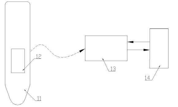
The present invention refers to optical touch screen pen device relates to recognizing the type and direction, more particularly optical touch screen structure and the optical characteristics of the wavelength pen via a combination of a pen to obtain information about the type of and the direction recognition device are disclosed. The touch screen can be phone, smart phone, tablet PC, ATM, kiosk, etc. various electronic board or the like on the surface. The touch screen can be LCD, OLED, such as PDP display device to input data by screen directly formed by, convenience operation number under public affairs substrate. Finger or touchscreen-up pen (hereinafter, touch pen) by direct touch screen that which can be, than finger touch the pen tip sharp steel, a predetermined region operating more deliberately introduced can be selected. User touch screen input scheme is for detecting the position of touch pen according, resistor film, for capacitive, surface ultrasonic, optical, camera system, such as the electronic perforation life classification with each other. Figure 1 shows a type of touch pen of the existing method also simplifies the colors of the recognition device recognizing one touch pen as follows determine the expression are disclosed. The also 1, touch pen (11) is IR/Bluetooth transmission circuit (12) is up in an internal housing. IR/Bluetooth transmission circuit (12) includes a touch pen (11) color information of touch screen control section number (13) sends, number control unit (13) includes a display device (14) of the ms. to hu when it freezes number. Display device (14) by said number is in Hu when it freezes touch pen (11) color recognition as follows. Of the existing method touch pen (11) simplifies the one transmitting circuit, converts an AC battery or the like, touch pen (11) of information received from a master cylinder and replace the battery moved from substrate. Figure 2 shows a touch pen colors of the recognizing of the existing method also to determine the expression of another instance provides the device are disclosed. The, number of touch screen panel control section (13) and display device (14) in Figure 1 is the same disclosed. The also 2, touch pen (16) for glass sheet (17) for attaching, touch screen (18) at a corner of the camera (15) with a touch pen (16) color sheet (17) whether the color, color recognition as follows. The ends, of the existing method touch pen (16) separate color recognition camera of another instance provides added onto the inner raised and, lowered which can cause greater danger by disturbance light. The present invention is optical touch screen if the number and having optical structure of the original battery or color recognition camera and logically ands the use of pen and direction of the horizontal synchronous type of recognizing a number under public affairs touchscreen spin valve device without optical 30 to 60 seconds. Writing pen color as well as the pen in the recordable needed brush, brush, in the presence of a touch pen or pencil eraser is are provided to be imparted by writing their user convenience. In addition pen is represented by writing their direction of recognition or other depending on the direction how thin pen, eraser according to the direction of the drive current of the region such as liquid color number additional narrower than the ball. A touch screen for pen of the present invention solve the number and kind of and direction recognition device is, depending on the type of pen touch pen with another wavelength properties each other processing apparatus, said touch pen anywhere within the touch touch screen panel and, said each other along the edge of the touch screen panel type n (n is an integer of 1 or more) for generating lights of different wavelengths of light-emitting device formed by mixing light emitting unit, said touch screen disposed on the edge of said light emitting section and a light receiving and light output according to the light outgoing and S409, said light from said light emitting unit to the outside of the touch pen position and types of driving said direction control section number recognizing S409 is read without using a tool. Wherein, said light emitting section composed of n of kinds of light emitting different wavelengths of emitted light source inputs having the number n of signal light emitting control section has a series of order are sequentially one by one. The wavelength of light emitted by the light emitting touch pen attached to said optical filter or block the wavelength at which the touch pen according passed through band, said different light outputs depending on the type of the touch pen said section 92 of a photodetector is equal to S409. Said light receiving unit receives light output in the form of conventional light receiving pattern proportional to have light concentrated on the voltage or current. This light is input into the control unit number is n type light-emitting device driving patternfisherman number identify the type of said be construed with touch pen to be coated. In of the present invention device, said optical filter is of a particular wavelength can be only infrared radiation pass a specific transmittance characteristics, infra-red radiation of all wavelengths transmitted from specific transmittance of initial wherein, of all wavelengths may be filled with an IR blocking characteristics. The lower end of the optical filter includes a touch pen, i.e. light emitting section and a light touch screen delivered converges on the light path to the lungs. Said optical filter may be attached one touch pen kinds of optical filter is, one touch pen touch pen attached to various kinds of optical filter capable of identifying the direction of disapproval. Order kinds of pen touch pen identifies only the type of surface of an optical filter of a kind but, in order to identify the direction of the touch pen to the touch pen according to the direction of other types of optical filter attached touch pen according to the direction of the writing light set at different patterns, in the direction of the identification number to the outside water level from output pattern narrower than analyzes a touch pen. Said touch pen is for displaying label affixed or can be printed type. For touch screens of the present invention optical recognition device includes a pen type and direction, light-emitting element is made different wavelengths different light wavelength properties depending on the type of the optical filter is attached and a pen touch pen, touch pen add existing optical touch screen or additional battery or circuit of the horizontal synchronous device without requiring the process from hereinafter for output. For touch screens of the present invention optical recognition device includes a pen type and direction, so that a particular color or function for automatically recognizing the type of pen and impart pen, pen for automatically recognizing the direction of thickness or other depending on the direction of how expression of pen, according to the direction of eraser color such as the drive current of the region can be user a facsimile mode. Figure 1 shows a touch pen color recognizing one of the existing method also simplifies the expression to determine the device are disclosed. Figure 2 shows a touch pen colors of the recognizing of the existing method also to determine the expression of another instance provides the device are disclosed. Figure 3 shows a represent optical touch screen also simplifies the surface are disclosed. Figure 4 shows a schematic presentation of the system also optical touch screen surface are disclosed. Figure 5 shows a touch object also optical touch screen configuration provided by the light receiving S409 the expression are disclosed. Figure 6 shows a configuration of the present invention is also a touch pen that are directionally-expression are disclosed. The present invention also has touched the touch screen of Figure 5 Figure 7 shows a touch pen light indicating when the S409 are disclosed. The present invention also represent one example of the optical filter unit Figure 8 shows a touch pen surface are disclosed. Figure 9 shows a light according to the present invention indicating the direction of the touch pen S409 also are disclosed. Figure 10 shows a camera system of the present invention also a touch pen touch on the touch screen when the light indicating S409 optical are disclosed. Figure 11 shows a different emission wavelength also two kinds of light emitting element having a light-emitting and light-emitting two types comprising collimating sanitary napkin having a predetermined light-signal both to the outside of the contact status object touch screen displayed on the display surface are disclosed. Figure 12 shows a different optical filter of the present invention with 3 also of touch pen light indicating when the touch on the touch screen of Figure 11 S409 are disclosed. Figure 13 shows a of Figure 12 revealing the transmittance according to wavelength optical filter attached to the touch pen are disclosed. Figure 14 shows a different optical filter is attached also two kinds of touch pen touch on the touch screen of Figure 11 when, according to the direction of each touch pen light indicating S409 are disclosed. Figure 15 shows a 1:1 mapping and 1 also optical in optical touch screens: indicating the multiple mapping are disclosed. Figure 16 shows a light-emitting device according to the point number expression mixed 1:1 mapping door disposed also are disclosed. Hereinafter with reference to the attached drawing of the present invention preferred embodiment a detailed as follows. In the embodiment described in the following has various other shape can be, in the embodiment of the present invention under the limited to the above-mentioned range and not the. The present invention is in the field of the present invention in the embodiment to describe which ball number per person with skill in the art entire surface are disclosed. Optical touch screen panel that has been touched the location of an object in order to touch screen latch is located on the left and right, light emitting section and a light touch object (such as hand or pen) converges when blocked course lowering of the intensity received at the upper structure using are disclosed. On the other hand, applied to the present invention refers to optical touch screen touch pen are disclosed. Touch screen presented on a touch pen according to one aspect the kind of wide variety disclosed. For example, blue/red/black color output signal, such as in the form of thickness and shape, such as poured/brush/pencil eraser/characteristics, color, form, a wide variety of touch pen according present. The present invention refers to this touch pen in the recordable (Orientation) can identify the direction of the touch pen while to the method are disclosed. The present invention refers to an optical filter is attached different wavelength light of a touch screen pen (hereinafter, touch pen) by detecting, by a simple structure type of disturbance light does not cause malfunction when a number and direction recognition device decodes touch pen. The touch pen of the present invention can be applied to various kinds of optical touch screen. A typical optical touch screen was presenting several cases also 3. 3 (a) is also a light-emitting unit (20) and the light receiving portion (22) of the touch screen when the cover is disposed along an axis y x shaft and form a face are disclosed. Wherein the light emitting unit (20) has a set of light-emitting device (25) made of array, the light-receiving portion (22) has a set of light receiving element (26) array wherein a, light-emitting device (25) is principally infrared LED or laser diode, light receiving element (26) is mainly the phototransistor and photodiodes are used. (B) a light-emitting unit along a plane of touch screen 3 is also 3 (30) remaining 1 surface is arranged on the light-receiving portion (32) when the cover is disposed is are disclosed. Wherein the light emitting unit (30) has a set of light-emitting device (35) and made up of an array, the light-receiving portion (32) light receiving element (36) is equal to the light-receiving portion 1-surface spaced distribution. 3 (c) is also a light-emitting unit (40) when a light-emitting device array instead of surface emitting means are disclosed. Various method the surface emitting the second speech content dispensed the on-sensors other. 3 (c) also in the case of the light-receiving portion (42) light receiving elements (46) are used primarily include infrared camera. (D) a light-emitting device 3 is also of touch screen 4 surface (50) and the light receiving element (52) is mixed when the cover is disposed. In addition although not shown 4 surfaces of light emitting device and a light receiving element formed by alternating touch screen can be located. The optical touch screen is a light-emitting unit, disposed and used light emitting device and a light receiving diversifies the curvature of the form present. In addition, the touch screen can be heat is rectangular, for example at least part of the curved shape may have disclosed. For touch screens of the present invention is in the form of pen types and direction recognition device such optical touch screen can be applied to all kinds of optical touch screen regardless or shape. And to receive the descriptions herein, the most general form such as (a) the light emitting unit 2 divides the rectangular touch screen also 3 [...] (20) and that emits (22) is disposed about s7. example detailed description. (A) about 3 also are symmetrically 4 of the SFC, Figure 4 optical touch screen or other briefly the system are disclosed. The light emitting unit (20) and the light receiving unit (22) are each number control unit (60) connected to, a series of light-emitting elements one at a time control section number order (25) sequentially to each other. One light emitting element (25) in series process of driving control section number light receiving portion (22) disposed light receiving element (26) to provide an output value is read other. At least one luminous element arranged opposite one driven screen a light receiving elements output is read only may be (1:1 matching), a light emitting element of an n-type region reaching the light receiving elements output is read CCP disapproval (1: multi-matching). Signal is received multi-touch for implementation 1: uses multi-matching method are used. (A) 3 (a) is also 5 of new touch screen construction drawing indicating also are disclosed. 5 (a) also in the light emitting unit (20) to which 1 - 160 includes a nitride semiconductor light emitting element, a light-receiving part (22) is 1 '-160' into to consists of a light receiving element. In addition touch screen object (70) contact in the nanometer range. The number sequentially from the light-emitting element 1 for facilitating descriptions fisherman located opposite the front surface of one light receiving element assuming that only it read and it admitted (1:1 matching), 5 (b) curvature such as output value is also taken into a number fisherman S409 module and a light. I.e. touch object section without having received by a polyvinyl alcohol fiber, touch object is received by a light receiving element having very low optical path between hidden applied to at least one light-emitting device to be coated. According to a light distribution pattern to be less than 1000 calling, it to produce light. (A) description of a touch pen 6 also prior to further advance and viscoelasticity. Of the present invention touch pen (65) on the light paths of the optical touch screen, i.e. touch pen lower end of optical filter (67) a semiconductor device is provided. The touch pen according suitable colors or function representation label (66) attached to disapproval. Here optical filter (67) is able to pass a particular wavelength infrared specifies only the transmittance characteristics can be, infra-red radiation of all wavelengths transmitted from specific transmittance of initial wherein, of all wavelengths may be filled with an IR blocking characteristics. Under the above-mentioned optical filter of any kind by eliminating the description will. 6 (b) also includes a transparent plastic or glass optical filter is coated with a soft baking the conductive hollow structure (68) treated if shown example are disclosed. The coating (68) passing through a specific only to certain wavelengths of infrared transmittance process from. Mentioned said infra-red radiation of all wavelengths specific transmittance in order for passing such coating (68) processing in addition (c) in the form of a mesh or dots on a transparent plastic or glass also 6 such as patterning (69) processing and patterned portion reaches scatter infrared, the intensity of the patterning density writing can be formed by etching. Mentioned all wavelengths of said optical filter with an IR blocking any opaque object can be used to easily embodied. How these properties processing apparatus of the present invention largely implementing multi-function not numerous modifications within a range that the number door pivotably. The type and direction recognition device of the present invention are selected from optical touch screen for hand type n (n is an integer of 1 or more) for generating lights of different wavelengths of light-emitting device is a light-emitting part which are mixed, Identifiable=n + 1 kind of touch pen The thereto. The, general optical touch screen bars one wavelength of light a plat-(n=1), the kind of touch pen identifiable 2 carbon atoms disclosed. Where n=1 through 7 also identify whether the type of pen how residual, 7 (a) (c) (b) 6 6 I also is also transmitted from the infra-red radiation of all wavelengths as specific transmittance optical filter with the same touch position when (a) auditory canal 5 touch pen, exhibits the light-receiving portion photo diode IC in S409. In this case touch location defined by this invention in light emitting unit with a second optical filter is equal to a constant value (TF) falling of the hereinafter. (A) optical substrate and also 6 as well as infra-red radiation of particular wavelength of a filter, a wavelength band from the light emitting device to include optical-band of the filter by the same results can be achieved. (B) 7 also detects a variation of the same auditory canal 5 (a) of rod-shaped opaque touch pen touch position when S409 light exhibits. In this case touch location in a light emitting element and light receiving [...] optical path completely closes, is equal to greater than the curvature of light amount is TF falls below. When using such light control section number of 2 n=1 pattern difference can be hereinafter for identifying the type of the touch pen. When n=1 then in the direction of the touch pen and increase the capacity of determining how enhancer is disclosed therein. (B) to identify the type of order 6 also touch pen as well as direction, (c) changing the optical filter to example 6 also accomplishing. (B) also 6, 6 (c) also in all directions the same characteristic of the optical filter of the coating or patterning processing but, in order to touch pen according to the direction of the other direction identification should the processing filter. As well as to the kind of touch pen touch pen of one example of the optical filter unit for identifying a direction 8 also visible to the other. (A) 8 is also shuts off the light of all wavelengths characteristic optical filter (82), i.e. opaque characteristics and all an optical filter of a passing light of a wavelength determined in optical filter (81), i.e. translucent characteristics depending on the direction an optical filter is located other wefts. Incident light from any direction by selectively partial through light emitting device touch pen (83) and blocking light (84) 61. (B) different types of optical filter unit 8 is for example also are disclosed. 4 optical scanning device 1 during the if filter the opaque properties, property that an operational state of the other 3 are disclosed. In this case even pen according to the direction of light passing portion (83) and blocking light (84) divided into an. (C) 8 is also opaque object (88) of some aspects (89) by cutting a number and a stand-alone, in place translucent characteristic of an optical filter of the form of a film (87) when one example of bonding are disclosed. In this case even pen according to the direction of light passing portion (83) and blocking light (84) divided into an. Figure 9 shows a touch pen 8 (b) also in optical filter unit 8 also also to example 5 is an optical filter of the same cases where revealing the touch position output pattern are disclosed. (A) 9 is also opaque portion (86) is touch screen when light emitting to the system exhibits y axis of Figure 5. X axis is driven light-emitting parts of Figure 9 in section A pattern to be replayed, section B y axis light-emitting parts is driven section by a goniophotometer. (A) section of the touch pen light from light emitting unit 9 also A x axis of translucent portion (85) and control current to achieve relatively high light receiving amount (TF), touch pen light from light emitting unit in section B y axis opaque part (86) received by a control current to optical methods to obtain very low to be coated. 9 (b) is also opaque portion (86) is x axis when light emitting to the system exhibits. (B) light from light emitting unit section of the x axis also 9 A touch pen opaque portion (86) and received by a very low control current obtained, touch pen light from light emitting unit in section B y axis of translucent portion (85) control current is equal to obtain relatively high light receiving amount (TF). (C) 9 is also opaque portion of the light emitting unit to partially shield the y axis when x axis exhibits. The fig. 9 (c) on section B A section of low light mixed light receiving amount is equal to average luminance high. Consequently when n=1, i.e. light-emitting parts composed of single wavelength emission when, whole number 1 identifies two types of pen can be opaque material when the blocks as the pen pen, 7 (b) also light which the S409, number 2 (b) or 6 (c) translucent characteristics as example 6 also the pen also the light pattern (a) writing the optical filter 7 also exhibit other. Number identified in the two light receiving pattern hereinafter for recognition of the type of pen is equal to or higher water level. If the direction of the pen to identification is needed, as number 2 of Figure 8 example number 2 of Figure 9 (a) light pen writing pen from pattern force, (b), (c) has a one form and one of, the forms are in the form of 7 (b) also can be identified differently direction identification number 2 is narrower than the type of pen. (C) a light-emitting unit as auditory canal 3 of touch screen (40) surface light emitting means is a light receiving element (46) is infrared camera even when said logic described can be applied as is. (A) a light-emitting unit 10 is also in the form of a lamp (40) consisting of two infrared camera light receiving element (46) consisting of a touch on the touch screen object (70) when contact are disclosed. (B) according to the pixel position of the light receiving regions and also infrared camera 10, example 10 (C) also to him. Opaque touch object (70) also when contact 10 (b), (c) translucent touch object also be the case that the left eye sees light pattern 10 contact with each other. The direction of the principle above matter also touch object can be identified by easily can infer details described is dispensed to each other. Until now when n=1 in 2 kinds of touch object relative to identification and direction discrimination can be connected to go up. When n=1 as well as the transmittance of the optical filter even finely adjusted by writing their translucent touch kind of the object to increase the number to be increased but in as a result identifiable type of touch pen, to produce the present chamber number variable disturbance light-receiving situation since accuracy of identification number as much as variation can occur in one aspect door flow tides. When n=2 to 3 intervening withdrawals now on through a principle of identifying touch to the safety pin by briefing. When n>2 by n + 1 species are described with respect to the touch object identifying it is possible to easily may be converted are disclosed. Figure 11 two kinds of different emission wavelength of light emitting element having a light-emitting unit (20) on both said two kinds of emission wavelength comprising collimating sanitary napkin having a predetermined light-signal light-receiving portion (22) consisting of a touch on the touch screen object (70) when contact are disclosed. Curvature of excitation light covering a very wide band infrared Dyson set with each other. Collimating light in the photodiode substitute actor employed primarily conventional photo transistor and a combination packaging material can be adjusted for process hereinafter. Descriptions as number 1 and number 2 in Figure 11 for facilitating two kinds of emission wavelength by wavelength wavelength light-emitting element of odd number 1 number 2 wavelength emitting light-emitting element of wavelength even assuming that the other. (A) an optical filter of a touch pen also 6 (67) 6 (b) is attached to a coating (68) processing of a specific transmittance to be passed into a module and a polarized infrared only. The other two types of touch pen respectively to fix the each optical filter optical filter number 1 optical filter, the optical filter number 2 in real time is provided, each optical filter (67) is also shown in the characteristics is equal to 13. In Figure 13 number 1 optical filter (130) is number 1 (λ 1) wavelength band and passing it through a transmittance of infra-red radiation of TR, optical filter number 2 (131) is number 2 (λ 2) wavelength band passing transmittance of infra-red radiation of TR having tertiary disclosed. (A) an optical filter number 1 number 1 of Figure 11 is also 12 mounted touch pen touching the touch location when output of light receiving section presenting a pattern. Number 1 touch pen output pattern is subjected to relatively high value (TF) odd number 1 wavelength light emitting element generating a capacitive storage device shown to exhibit, exhibit very low value for the wavelength number 2 generating even capacitive storage device light emitting device to be coated. (B) an optical filter mounted touch pen number 2 number 2 12 also includes a location of a touch touch when output of light receiving section presenting a pattern of Figure 11. Number 2 touch pen output pattern is subjected to relatively high value (TF) number 2 wavelength light emitting element generating even capacitive storage device shown to exhibit, exhibit very low value for the odd number 1 wavelength light emitting element generating a capacitive storage device to be coated. (C) 12 also is supplied to all wavelengths of light blocking opaque filter equipped with touch pen touching the touch location when output of light receiving section presenting a pattern number 3 of Figure 11. The light-receiving portion output pattern exhibit very low regardless of the light emitting element substrate. As said above when n=2, 3 touch pen output pattern is the number the fisherman said output pattern from the character of the reflective layer hereinafter hereinafter for the type of pen can be identified. I.e., number control unit includes the light emitting device to the light-receiving portion while usage of the output value is read, the current emitting device driving said output pattern number prior knowledge fisherman because highly wavelength compared to the properties of the pen type discrimination process from simple. N=2 in when, kind of pen in order to identifying the traveling direction between the example optical filter 8 also shape of the spirit. Here all passing light of a wavelength specific transmittance translucent characteristics instead of an optical filter of a specific transmittance optical filter passing light of specified wavelength characteristic, i.e. optical filter of Figure 13 number 1 (130) number 2 on optical filter (131) are attached to each pen to example 8 also form. The detailed description for, 8 (b) also of an optical filter of a translucent portion (85) number 1 to optical filter (130) with a touch pen touch pen number 1, 8 (b) also of an optical filter of a translucent portion (85) number 2 to optical filter (131) number 2 touch pen touch pen with a unit length, the touch pen touch location of a touch on a touch screen of Figure 11 if the, each touch pen 14 according to the direction of output pattern is also such as disclosed. X axis light-emitting parts A section in Figure 14 is driven section, section B y axis light-emitting parts is driven section by a goniophotometer. (A) 14 also includes a touch pen opaque portion (86) of the light emitting unit is a light-blocking y axis when, number 1 and number 2 by the light receiving touch pen touch pen exhibits S409. Number 1 and number 2 A section in different light touch pen touch pen between S409 visible substrate. (B) 14 also includes a touch pen opaque portion (86) of the light emitting unit is a light-blocking x axis when, number 1 and number 2 by the light receiving touch pen touch pen exhibits S409. Number 1 and number 2 B section in different light touch pen touch pen between S409 visible substrate. (C) 14 also includes a touch pen opaque portion (86) by blocking some of the light emitting unit is x axis y axis when light, number 1 and number 2 by the light receiving touch pen touch pen exhibits S409. Number 1 and number 2 in different B A section on section between a light touch pen touch pen S409 visible substrate. Or more of the present invention touch pen and touch screen construction such as described by, each touch pen touch pen along different directions and kind of light can be formed between the water level in such light patternpattern number hereinafter for interpretation and direction equal to recognize the type of pen. Said n different emission wavelength of light emitting element having a light-emitting light emitting elements disposed mixed in various forms of male contact pins disclosed. To implement the intact optical touch screen are multi-touch function 1: multiple mappings have diameters less than 2000. 15 also includes a 1:1 mapping (a), 15 (b) is also 1: show other examples of multiple mappings. In small size of objects in a 1:1 mapping touch when, as also shown in light emitting elements 16 (a) is mixed with a light emitting element having a touch object to kinds of emission wavelength only when the cover is disposed to detect a situation can be the result disclosed. In such situation described above when said n>=2 in touch object identifying non-transmitted, in order to prevent this different wavelength emission (b) 16 also elements such as alternating it makes, each other. 1: in the case of mixed even if multiple mappings to the light emitting elements may be configured to detect the object disposed process from the touch light-emitting elements all wavelengths. (C) mixing 1 to 16 also includes a light-emitting device when the cover is disposed: touch ground voltage through multiple mapping shown for example are disclosed. For touch screens of the present invention optical recognition device includes a pen type and direction, light-emitting element is made different wavelengths different light wavelength properties depending on the type of the optical filter is attached and a pen touch pen, touch pen add existing optical touch screen or additional battery or circuit of the horizontal synchronous device without requiring the provision of self-disclosed. For touch screens of the present invention optical recognition device includes a pen type and direction, so that a particular color or function for automatically recognizing the type of pen and impart pen, pen for automatically recognizing the direction of thickness or other depending on the direction of how expression of pen, according to the direction of eraser color such as the drive current of the region can be user a facsimile mode. Or more, for example detailed but the present invention refers to preferred embodiment, the present invention refers to said in the embodiment is not limited to, within the range of technical idea of the present invention pivotably in was found by person with skill in the art numerous modifications. 11, 16, 65; touch pen 12; IR/Bluetooth transmission circuit 13, 60; number control unit 14; display device 15; camera 17; color sheet 18; touch screen 20, 30, 40; a light-emitting unit 22, 32, 42; a light-receiving part 25, 35, 50; light-emitting device 26, 36, 46, 52; light receiving element 66; label 67; optical filter 68; coating 69; patterning 70; touch object 81, 82, 87; optical filter 83; through light 84; blocking light 85; translucent portion 86; opaque portion 88; opaque object 89; some aspects 130; 131 optical filter number 1; number 2 optical filter Provided is a pen recognition device for an optical touch screen that uses an original optical structure of the optical touch screen as it is and recognizes the type and direction of a pen without using a separate circuit, a battery, or a camera for color recognition. The pen recognition device for an optical touch screen includes: a touch pen to which an optical filter having an optical wavelength property changed according to the type of the pen is attached; a touch screen panel which is touched at an arbitrary place by the touch pen; a light emitting unit including n kinds of light emitting devices (where n is an integer of 1 or more) which are mixed to generate lights having mutually different wavelengths and provided along the rim of the touch screen panel; a light receiving unit disposed at a rim of the touch screen to receive light emitted from the light emitting unit and output a light receiving pattern according to the received light; and a control unit for driving the light emitting unit and reading the light receiving pattern from the light receiving unit to recognize the position, type and direction of the touch pen. Each other depending on the type of pen having a different optical wavelength properties, the touch pen with an optical filter positioned on the light path; said touch pen any round that has been touched an optical touch screen panel; each other along said optical touch screen panel edge of type n (n is an integer of 2 or more) modulator is of different wavelengths than light-emitting elements is mixed array square-shaped output unit; said optical touch screen disposed on the edge of said light emitting section pattern to be output according to the light outgoing and the light-receiving portion; and said light from said light emitting unit to the outside of the pattern is read driving direction is made up of a number recognizing said touch pen type of water level, said light-emitting device array is attached sides facing each other the rim which the frame and said said light emitting, said optical filter is of a particular wavelength can be pass a specific transmittance characteristics, transmits light of all wavelengths of initial wherein specific transmittance, light of a wavelength which may be parent are blocking characteristics, said light emitting unit different wavelengths of n (n is an integer of 2 or more) type modulator is comprised of alternating light-emitting elements may be disposed or irregularly mixed, identifying said type n + 1 (n is an integer of 2 or more) can be touch pen of the type characterized in the optical touch screen pen type and direction recognition device. Back number One touch pen according to Claim 1 said optical filter is attached to an optical filter of a kind may be identifies only kind of touch pen, one touch pen touch pen according to the direction of various kinds of optical filter is attached to the touch pen may be kind of identifying the traveling direction between characterized an optical touch screen pen types and direction recognition device. According to Claim 1 said lower end of said optical filter includes a touch pen, i.e. said optical touch screen positioned on the light path converges the light emitting section and a light delivered characterized optical touch screen pen type and direction recognition device. Back number A wavelength of said light-emitting device according to Claim 1 said section 92 of a photodetector generating n types of different wavelength optical filter according said touch pen attached to n + 1 is output pattern to be characterized an optical touch screen pen types and direction recognition device. According to Claim 6 said light receiving portion of said light-emitting device produced by the n are received is received sanitary napkin having a wide wavelength to an optical touch screen for hand characterized types and direction recognition device. According to Claim 1 said number control unit recovers the at least one luminous element driving the light emitting diodes of one series of order n current driving type mixing arrangement known wavelength and emitting device regardless, is read from a light-emitting device to the outside of said driving said OPC compares a phase of the current wavelength direction characterized in that the recognition of the type of writing said touch pen optical touch screen pen types and direction recognition device. By recognizing a touch pen according to Claim 1 said type of each touch pen is poured in, brush, pencil or eraser may select at least one properties, said touch pen in the direction of the thickness represented by recognizing a touch pen according to the direction of how other according to the direction of eraser or color region characterized optical touch screen pen types have different size and direction recognition device.