나노포러스구조를 구비하는 연료전지 촉매전극 제조방법 및 이에 의한 연료전지 촉매전극
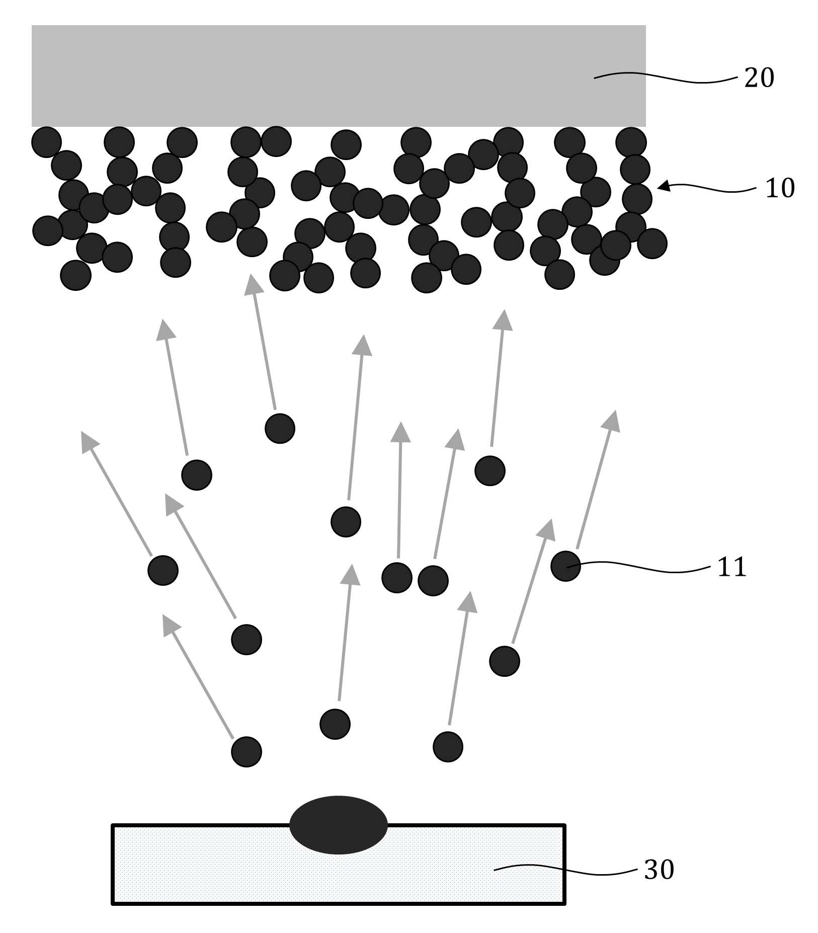
The present invention refers to a fuel cell catalyst electrode manufacturing method and a fuel cell by nano gun [le[le] structure relates to catalytic electrode, more particularly catalyst electrode catalyst layer formed by vapor deposition nano with gun [le[le] structure particularly efficient fuel cell catalyst electrode manufacturing method and resulting fuel cell catalyst electrode are disclosed. Recently in various fields constituent faces are fuel cell system, the generation of the first polymer electrolyte fuel cell (PEMFC) during various fuel cell system, has a high energy efficiency and current density and household power car number ball and 2000. Polymer electrolyte fuel cell (PEMFC) is hydrogen ion exchange properties having the porous polymer membrane fuel cell are disclosed. Other fuel cell scan unit temperature is low polymer electrolyte fuel cell having a higher output density and highly efficient characterized, loading change response characteristics disclosed. In addition, other fuel cell electrolyte needing replenishment but due to evaporation of liquid electrolyte, since the polymer membrane as electrolyte in the polymer electrolyte fuel cell need not disclosed. Polymer electrolyte fuel cell (PEMFC) of basic cell anode (anode), cathode (cathode), electrolyte (electrolyte) or multi-element comprising of 3 to which, double-electrode catalyst layer consists of the support layer. Catalyst contains a polymer electrolyte membrane in contact with the latter serving as a substantial electrochemical reaction has taken place, polymer electrolyte fuel cell performance in valuable element determining pain, a carbon support a conventional catalyst layer platinum particles received from the first stage, carbon support catalyst layer formed of platinum and excellent fuel cell efficiency of the entire system can be more active than the catalyst layer etc. desired. A compensation registration patent number 10 - 1035620 call (title of the invention: electrode for fuel cell, and including fuel cell and fuel cell electrode for manufacturing method, is combined with a load. prior art 1 hereinafter) in, carbon paper or carbon cloth (carbon cloth) is positioned on the surface of the electrode substrate (carbon paper) in polar functional group including activated carbon pixel layer, and said surface of said nano carbon nano carbon deposited coating which will bind to the activated carbon small layer polar functional group and including catalyst including a catalyst layer on the electrode for fuel cell, a manufacturing method of the electrode fuel cell and fuel cell including the same disclosure as follows. the prior art 1, the role of the gas diffusion layer (gas diffusion layer: GDL) electrode onto the substrate after wet coating defines active carbon nanoparticles and bonds, forming a catalyst layer on the nanoparticles deposited over the coating step, door number point number 1 that generally as an ion implantation mask. In addition, the prior art 1, or dip coating or spray coating such as activated carbon slurry method (dip) defines wet coated dielectric thin film is deposited on the binder and organic solvent, acid solution or basic solution for the surface preparation of electrode substrate be used, environment material before the door number point number 2 harmful to the human body. And, the prior art 1, platinum or platinum alloy catalyst for the layer that door number point number 3 increase cost. The technical objectives of this invention is descriptive and not one number to number mentioned above, specific number are not in yet another technique referred in the art to clearly understand the present invention from the substrate is provided below may be person with skill in the art are disclosed. Said techniques in order to achieve a specific number, one embodiment of the present invention examples, the steps of providing a polymer electrolyte fuel cell (PEMFC) (i) membrane (Membrane); (ii) securing said membrane deposition chamber; (iii) said deposition chamber so as to form a step further; (iv) clamp the deposition chamber forming a process pressure injected into said process gas flow is initially; (v) according to the temperature of said membrane 50 °C hereinafter step; (vi) deposition material (heat source) won increasing temperature of said evaporation container forming a deposition material produced in step (vi) (vii) and said anode of said membrane surface forming said deposition particles comprising child node catalyst layer and, after said anode of said child node catalyst layer, said cathode of said membrane to said it digs up, cow [tu[tu] catalyst layerchild node catalyst layer makes the duration of the process surface forming a fuel cell catalyst electrode manufacturing method number under public affairsgun [le[le] structure synthesized on a substrate. In example of the present invention embodiment, between said step and said (ii) (iii), said membrane and said evaporation won is desired locations (heat source) heat cutting having function of baffles (baffle) further includes providing a can be done via the disclosed. In example of the present invention embodiment, said baffle, said deposition for migration of particles can be with a plurality of it became other hole (hole). In example of the present invention embodiment, said baffle, at least one of two hereinafter 3 can be formed on the semiconductor substrate 1. In example of the present invention embodiment, said baffle metal, alloy and ceramic material selected from the group consisting of one or more material can be formed. In example of the present invention embodiment, the distance between said membrane and said baffle, 0. 01 45 centimeter (cm) or more can be made hereinafter. In example of the present invention embodiment, said deposition particles, platinum (Pt), palladium (Pd), cobalt (Co), gold (Au), is (Ag), copper (Cu), chromium (Cr), iron (Fe), manganese (Mn), nickel (Ni), titanium (Ti), zinc (Zn), lead (Pb), vanadium (V), aluminum (Al), molybdenum (Mo) be a selected from the group consisting of one or more metal particles. In example of the present invention embodiment, said deposition particles, manganese (Mn), molybdenum (Mo), tungsten (W), tin (Sn), nickel (Ni), copper (Cu), titanium (Ti), vanadium (V), chromium (Cr), iron (Fe), cobalt (Co), zinc (Zn), is (Ag), gold (Au), platinum (Pt), iridium (Ir), ruthenium (Ru), lithium (Li), aluminum (Al), antimony (Sb), bismuth (Bi), magnesium (Mg), silicon (Si), indium (In), lead (Pb) and palladium (Pd) composed of oxide of the metal oxide particles of at least one selected from the group consisting be a. In example of the present invention embodiment, (vii) said step, said deposition chamber process gas species, process pressure, temperature of said membrane, said membrane and said distance between said one or more deposition and evaporation won of heating temperature change over time varying said energy to the deposition particle size, said membrane and said adjacent portion in said it digs up, cow [tu[tu] catalyst layerchild node catalyst layer result relatively high density can be formed to have uniform quality. In example of the present invention embodiment, the distance between said membrane and said evaporation won, 3 or more 100 centimeter (cm) hereinafter to be disclosed. In example of the present invention embodiment, said (v) step, cooling said membrane seal secured can be carried out. In example of the present invention embodiment, step (iv) said initial process pressure is, 0. 01 Torr or more implementation being 30 Torr hereinafter. In example of the present invention embodiment, said deposition of speed, 0. 01 to 10 micrometers (micro m/min)/minutes implementation being. In example of the present invention embodiment, said (iv) steps gas, and argon as inert gas (Ar), nitrogen (N2 ), Helium (He), neon (Ne), krypton (Kr), xenon (Xe), radon (Rn) can be at least one selected gas. In example of the present invention embodiment, the particle generation deposition at said step (vi), can be ten evaporation laws by sputtering or evaporation. Said techniques in order to achieve a specific number, one embodiment of the present invention examples, for polymer electrolyte fuel cell (PEMFC) electrode substrate (i) shape; (ii) securing said electrode substrate deposition chamber; (iii) said deposition chamber so as to form a step further; (iv) clamp the deposition chamber forming a process pressure injected into said process gas flow is initially; (v) according to the temperature of said electrode substrate 50 °C hereinafter step; (vi) deposition material (heat source) won increasing temperature of said evaporation container forming a deposition material produced in step (vi) (vii) and said anode of said surface forming said particles deposited on the electrode substrate comprising child node catalyst layer and, after said anode of said child node catalyst layer, said cathode of said electrode substrate formed to face said child node catalyst layerㅀ[...] makes it digs up, cow [tu[tu] catalyst layer synthesized on a fuel cell catalyst electrode manufacturing method forming a number gun [le[le] structureunder public affairs substrate. In example of the present invention embodiment, between said step and said (ii) (iii), said electrode substrate and said evaporation won is desired locations (heat source) heat cutting having function of baffles (baffle) further includes providing a can be done via the disclosed. In example of the present invention embodiment, (vii) said step, said deposition chamber process gas species, process pressure, temperature of said electrode substrate, said electrode substrate and said distance between said one or more deposition and evaporation won of heating temperature change over time varying said energy to the deposition particle size, as a result said electrode substrate in said adjacent portion and said it digs up, cow [tu[tu] catalyst layerchild node catalyst layer relatively high density can be formed to have uniform quality. Said techniques in order to achieve a specific number, one embodiment of the present invention examples, the present invention is a fuel cell catalyst electrode manufacturing method number by nano gun [le[le] structure bath, specific surface area (specific surface area) value is 0. 1 to 600 m2 Characterized in fuel cell/g nano gun [le[le] structureit digs up, cow [tu[tu] catalyst layerchild node catalyst layer and catalytic electrode number under public affairs substrate. In example of the present invention embodiment, said child node catalyst layer and said it digs up, cow [tu[tu] catalyst layer, diameter 1. 0 to 100 nanometer (nm) in mesopores (mesopore) on diameter 0. 5 micrometers (micro m) or more (macropore) macropores can be simultaneously. Said techniques in order to achieve a specific number, one embodiment of the present invention examples, of the present invention fuel cell catalyst electrode is included in both being synthesized on a base having a polymer electrolyte fuel cell number gun [le[le] structureunder public affairs substrate. The present invention refers to, like the surface of a base polymer electrolyte membrane or electrode without the need of nanosized carbon support, the surface of a base polymer electrolyte membrane or electrode layer consists nano gun [le[le] structure directly forming, in a single process fuel cell catalyst electrode number can be simplify number 1 can be formed with a high pressure liquid coolant and effect. In addition, the present invention refers to, sequentially grown layer consists nano unit structure responding process, an increase in foreign matter along the porous structure has an improved reaction (specific surface area), number 2 gas diffusion excellent in both increased catalytic activity that effect. And, the present invention refers to, polymer electrolyte membrane or electrode substrate directly onto the exterior surface to form a catalyst layer thickness is reduced depositing catalyst electrode, run a larger fuel cell stack can be multi-stack upon the same volume of number 3 effect can be effectively. The effect of the invention is confined within said has the effect, the constitution of the invention including a detailed description of the invention or claim deduced from all possible effect is understood to should. Figure 1 shows a general outline of the present invention embodiment that the catalyst layer is formed processes according to example membrane also are disclosed. Figure 2 shows a process of the present invention embodiment example according to deposition chamber deposition at a mimetic also are disclosed. Figure 3 shows a general outline of the present invention embodiment also that the catalyst layer is formed an electrode substrate according to example processes are disclosed. Example SEM Image according to Figure 4 of the present invention embodiment catalyst layer are disclosed. Figure 5 shows a variation example of the present invention embodiment current mill according to cell voltage graph also are disclosed. Figure 6 shows a graph indicating a change in the current density according to example of the present invention embodiment also power mils are disclosed. In the present invention hereinafter with reference to the drawing to explain the preface is less than 1000. However the present invention refers to several different can be embodied in the form of, for example and not the confined within a the embodiment taught herein. The present invention is described in drawing and unambiguously account for when the dispensed portion that is independent, like part subjected to a similar drawing code is configured to receive through the entire specification. The entire specification, any portion to other assistant "(connection, contact, coupled) connected" when, this "connected directly" as well as when, the other interposed therebetween intermediate comprises a unit when "indirectly connected". In addition any components that "comprising" when any portion, particularly the opposite substrate under the outside components without other components of the other number which is further switched to each other. A term used in a particular embodiment to account for example specification only is used, the present invention intending to be define is endured. It is apparent that a single representation of the differently in order not providing language translators, comprising plurality of representation. In the specification, the term "comprising" or "having disclosed" specification of articles feature, number, step, operation, components, parts or specify a combination not present included, another aspect of one or more moveable number, step, operation, component, component or a combination of these is understood to presence of or additionally pre-times those possibility should not number. For example products on the attached drawing of the present invention embodiment hereinafter detailed the on-sensors other. First, cathode (cathode) comprising a fuel cell anode (anode) with membrane (Membrane) (20) child node catalyst layer nano gun [le[le] structure (10) forming a fuel cell catalyst electrode manufacturing method and it digs up, cow [tu[tu] catalyst layer described the on-sensors other. Figure 1 shows a general outline of the present invention embodiment according to example child node catalyst layer membrane deposition also formed processes degrees and, for example according to Figure 2 of the present invention embodiment deposition chamber deposition at a mimetic process are disclosed. To correspond, polymer electrolyte fuel cell (PEMFC) membrane (Membrane) (20) can be prepared. Wherein, membrane (Membrane) (20) is a proton conducting big. Membrane (20) material is preferably a fluorine-based ionomer (Nafion) can be formed like a proton conducting how all of the materials can be used. Second step, deposition chamber (100) due to the fact (20) can be fixed. Third step, deposition chamber (100) can be made further. Evacuation of process can be suitably performed using equipment which, thereof can require not necessarily form a complete vacuum. Between the second and third steps, membrane (20) for evaporating a won (heat source) (30) is heat cutting desired locations having function of baffles (baffle) (40) can be provided. Wherein, baffle (40) deposited particles (11) for movement of the plurality of it became other hole (hole) can be formed. At this time, the shape of the hole (hole) can be won or polygonal. Baffle (baffle) (40) is, evaporation of deposition material when a semiconductor substrate on which a thermal energy is supplied by radiation or convection or conduction effectively transmitted through number billion, membrane (20) can be a low temperature of, membrane (20) can be minimize temperature increases occur in the surface. The lamp material membrane (20) cooling unit (50) can be not cooled uniformly by, in this case child node catalyst layer (10) or it digs up, cow [tu[tu] catalyst layer generated can be non-uniform, a phenomenon baffle (40) prevented the launching the application disclosed. In addition, the deposition particle (11) flow baffle (40) to number by the deposition chamber (100) and to minimize the depositing material deposited inner wall, the direction of movement of deposition material membrane (20) so as to be twisted when deposited. The total hole area, baffle (40) of the whole area, 0. 70% hereinafter be a ratio of 1% or more. The total hole area of the baffle (40) the whole area 0. Is below 1%, the deposition particle (11) keep down and restrict the passage of the deposition efficiency are lower, the total hole area of the baffle (40) is greater than the whole area 70%, baffle (40) can be effect and thermal billion number. Hole is, constant size can be formed, baffle (40) in a central portion of the inner space formed in the nozzle is so size changes gradually holds disapproval. In addition, hole is, constant and may be formed at regular intervals, so that the uniformity of deposition variation of different intervals along and disposed so as to be formed may be filled. Baffle (40) is, at least one of two hereinafter 3 can be formed on the semiconductor substrate 1. Baffle (40) has a thickness of, 0. 2 hereinafter 30 millimeter (mm) or more may be disclosed. Baffle (40) has a thickness of, depending on the size of the hole or, in efficiency 0. 2 millimeter (mm) or more 30 millimeter (mm) hereinafter Cu2Se. Baffle (40) having a thickness of 0. 2 millimeter (mm) is below, baffle (40) the thermal billion number effect baffle (40) and may cause a decrease in the durability of, baffle (40) millimeter (mm) thickness of 30 greater than the, deposition particles (11) can be is considerably limited throughput. The thickness in a range of, baffle (40) can be formed on the semiconductor substrate 3 at least one of the two 1 hereinafter, but several layers formed in the material is high efficiency number accepts the high thermal billion, billion number but the other layer is formed it is that expense material 670 is thermal energy, considering cost and efficiency can be selectively selecting material. But, baffle (40) the plurality of layer in the form of the inner surface and each hole in a variety of divided, each divided area between deposition of nano-size particles (11) is deposited, deposition particles deposited in a hole (11) since the AC magnetic fields are, the deposition particle passing through hole (11) can be disturb a flow of. This phenomenon is baffle (40) is formed on the semiconductor substrate so that the at least one 4 when significant, baffle (40) is formed of two layer can be preferably 3 hereinafter. Baffle (40) metal, alloy and ceramic material selected from the group consisting of one or more material can be formed. Baffle (40) such that the number billion thermal energy at an elevated temperature, heat resistance material having low thermal conductivity and number bath 1308. Baffle (40) iron (Fe), titanium (Ti), molybdenum (Mo), cobalt (Co), nickel (Ni), tungsten (W), beryllium (Be), lead (Pb), tin (Sn), silicon (Si), chromium (Cr), zinc (Zn), copper (Cu), aluminum (Al) made of single metal and their alloy, or carbon steel, stainless steel, bronze, brass, beryllium - copper alloy, copper - aluminum alloy, cubic boron nitride (BN), aluminum oxide (Al2 O3 ) A high-refractive-alloy or oxide bath number can be disclosed. In addition, baffle (40) alumina, silicon nitride, silicon carbide, zirconia ceramic material such as their number bath using ceramic composite material can be disclosed. Membrane (20) and an air baffle (40) and the distance between the, 0. 01 45 centimeter (cm) or more can be made hereinafter. Membrane (20) and an air baffle (40) distance between, 0. 01 centimeter (cm) is below, membrane (20) and an air baffle (40) can be deposition process can be difficult to flag number description below, 45 centimeter (cm) is greater than, baffle (40) deposition material passed through the membrane (20) can be taken out of the chamber will not reach the vapor deposition can be lowered. In this case, membrane (20) won pipe (30) between a plurality of baffle (40) be [e[e] it will do number are installed in the deposition process. Membrane (20) won pipe (30) and the distance between the, 3 or more 100 centimeter (cm) hereinafter to be disclosed. Membrane (20) for evaporating a won (30) distance between, 3 centimeter (cm) is below, membrane (20) number of magnets becoming a deposition efficiency are considerably reduced and, due to the high temperature child node catalyst layer (10) or it digs up, cow [tu[tu] catalyst layer portions can be difficult, the greater than 100 centimeter (cm), deposition efficiency are reduced levels of deposition thereof can not required. Fourth step, vacuum deposition chamber (100) is in early pressure process gas into the process gas can. Wherein, the pressure early, 0. 01 Torr or more implementation being 30 Torr hereinafter. 0 initial process pressure. 01 Torr is below, child node catalyst layer (10) formed in a dense or it digs up, cow [tu[tu] catalyst layerchild node catalyst layer (10) or there can be (pore) it digs up, in cow [tu[tu] catalyst layer pores is formed, is greater than 30 Torr, membrane (20) within a particle size and uniformity can be difficult to maintain. 30 Torr under the process pressure greater than the deposition particle (11) to the membrane (20) undergoing a collision too much until reaching's oldest. Process gas can, and argon as inert gas (Ar), nitrogen (N2 ), Helium (He), neon (Ne), krypton (Kr), xenon (Xe), radon (Rn) can be at least one selected gas. However, the deposition particle (11) on if not react with a limited gas does not. Fifth step, membrane (20) can be set to a temperature of 50 °C hereinafter. In this case, membrane (20) cooling unit (50) can be tightly secured. In this case membrane (20) can be kept at a constant temperature. In addition, the function for rotation, can be advantageously uniform deposition. Order to enhance the membrane to nano gun [le[le] structure (20) to maintain a certain temperature of the need to flow tides. In the present invention membrane (20) -196 °C temperature of (liquid nitrogen vaporization point) or more can be isothermal holding temperature of 80 °C hereinafter. Membrane (20) than the temperature of -196 when disposed radially, with the use of helium or liquid received from the separate cooler to be used circular metal plate, membrane (20) when the temperature too high, so that energy of the deposited material reduced in more-than-necessary number under public affairs pores, particles and increases in size, nano in gun [le[le] structure operates simultaneously to be inside the pin is too dense. The preferably 50 °C hereinafter can be recommended to maintain isothermal. In addition, membrane (20) on, locally significantly if any temperature difference, membrane (20) is of a nano gun [le[le] structure local nonuniformity can occur, even if error positive temperature variation within that process inevitably on minus 5 °C manages, more preferably within plus minus 1 °C can be managing. In an associate, deposition material (heat source) won evaporation container (30) forming a deposition temperature control can. The deposition particle (11) is, platinum (Pt), palladium (Pd), cobalt (Co), gold (Au), is (Ag), copper (Cu), chromium (Cr), iron (Fe), manganese (Mn), nickel (Ni), titanium (Ti), zinc (Zn), lead (Pb), vanadium (V), aluminum (Al), molybdenum (Mo) be a selected from the group consisting of one or more metal particles. In addition, the deposition particle (11) is, manganese (Mn), molybdenum (Mo), tungsten (W), tin (Sn), nickel (Ni), copper (Cu), titanium (Ti), vanadium (V), chromium (Cr), iron (Fe), cobalt (Co), zinc (Zn), is (Ag), gold (Au), platinum (Pt), iridium (Ir), ruthenium (Ru), lithium (Li), aluminum (Al), antimony (Sb), bismuth (Bi), magnesium (Mg), silicon (Si), indium (In), lead (Pb) and palladium (Pd) composed of oxide of the metal oxide particles of at least one selected from the group consisting be a. The deposition particle (11) generation of, can be ten evaporation laws by sputtering or evaporation. In seventh, an associate deposition particles produced in step (11) is anode direction membrane (20) child node catalyst layer surface (10) can be formed. Wherein, anode direction membrane (20) child node catalyst layer surface (10) followed by a, child node catalyst layer (10) makes the duration of the process of the membrane surface it digs up, cow [tu[tu] catalyst layer cathode direction can be formed. In child node catalyst layerseventh (10) during a it digs up, cow [tu[tu] catalyst layer or formed, deposition chamber (100) of process gas species, process pressure, membrane (20) temperature, membrane (20) won pipe (30) and the distance between the deposition particles (11) heating temperature of one or more deposition particles over time (11) varying the energy size, as a result child node catalyst layer (10) and it digs up, cow [tu[tu] catalyst layer in membrane (20) portion contiguous with uniform quality can be formed to have a relatively high density. (Hereinafter, child node catalyst layer (10) the density of the inner gradient the operating requirements, even it digs up, cow [tu[tu] catalyst layer can be force. And, child node catalyst layer (10) or in it digs up, cow [tu[tu] catalyst layer, membrane (20) for the portion of the adjacent inward direction and thickness direction, thereby forming in a thickness direction and vice versa are disclosed. Hereinafter, are the same.) In the second process pressure seventh performed in time (gradually) progressively reducing or discretely (discretely), child node catalyst layer (10) within, child node catalyst layer relative density (10) can be reduced thickness thereby forming progressively or discretely. At this time, progressively (gradually) relative density (layer) without forming a reduction according to a separate layer continuously decreases from the components, discretely separate layer (layer) relative density (discretely) according reduction while form means that the can is reduced step by step. Excitation relative density, child node catalyst layer (10) distribution density and, quantitative include bulk (bulk) density of child node catalyst layer contrast material (10) to a density of display can be. The description hereinafter are the same. child node catalyst layer (10) in a direction in micro density, child node catalyst layer (10) child node catalyst layer in distribution density (10) thereby forming an thickness can be decrease. In this case, child node catalyst layer (10) in membrane (20) so that the free portion and closer nano gun [le[le] structure higher relative density, membrane (20) and child node catalyst layer (10) can be relatively enhance adhesion. And, child node catalyst layer (10) in membrane (20) distal from the lower portion of nano gun [le[le] structure and relative density, the child node catalyst layer (10) if most angle of relative density is lowest, child node catalyst layer (10) and an outer contact area can be maximize. The gate electrode is formed membrane (20) to child node catalyst layer (10) while stably with, child node catalyst layer (10) gas diffusion in can be widened. child node catalyst layer (10) to implement uniform quality thickness thereby forming an decreasing density, deposition particles (11) progresses along and decreasing energy of deposition is necessary, in order along the same process pressure stepwise increasing over time can be required. The deposition particle (11) of speed 0. 01 to 10 micrometers (micro m/min)/minutes implementation being. The deposition particle (11) 0 deposition of speed. 01 micrometers/minutes (micro m/min) is below, too low productivity disadvantage which, is greater than 10 micrometers/minutes (micro m/min), which apply to the power input terminal of the renewable raw material for evaporating, so as nano gun [le[le] structure can be damaged. Hereinafter, a fuel cell having an anode (anode) electrode substrate contained in the cathode (cathode) (60) child node catalyst layer nano gun [le[le] structure (10) forming a fuel cell catalyst electrode manufacturing method and it digs up, cow [tu[tu] catalyst layer described the on-sensors other. Figure 3 shows a general outline of the present invention embodiment also that the catalyst layer is formed an electrode substrate according to example processes are disclosed. To correspond, for polymer electrolyte fuel cell (PEMFC) electrode substrate (60) can be prepared. Electrode substrate (60) includes a gas diffusion layer (gas diffusion layer: GDL) coated carbon paper or carbon cloth (carbon cloth) serves small layer activated carbon (carbon paper) can be means. Second step, deposition chamber (100) to electrode substrate (60) can be fixed. Third step, deposition chamber (100) can be made further. Between the second and third steps, electrode substrate (60) evaporator for won (heat source) (30) is heat cutting desired locations having function of baffles (baffle) (40) can be provided. Fourth step, vacuum deposition chamber (100) is in early pressure process gas into the process gas can. Fifth step, electrode substrate (60) can be set to a temperature of 50 °C hereinafter. In an associate, deposition material (heat source) won evaporation container (30) forming a deposition temperature control can. In seventh, an associate deposition particles produced in step (11) is an electrode substrate for anode direction (60) child node catalyst layer surface (10) can be formed. Wherein, an electrode substrate for anode direction (60) child node catalyst layer surface (10) followed by a, child node catalyst layer (10) makes an electrode substrate for the duration of the process the cathode direction (60) it digs up, cow [tu[tu] catalyst layer face can be formed. In child node catalyst layerseventh (10) during a it digs up, cow [tu[tu] catalyst layer or formed, deposition chamber (100) of process gas species, process pressure, electrode substrate (60) temperature, electrode substrate (60) evaporator for won (30) and the distance between the deposition particles (11) heating temperature of one or more deposition particles over time (11) varying the energy size, as a result child node catalyst layer (10) and it digs up, cow [tu[tu] catalyst layer electrode substrate in (60) that is part adjacent uniform quality can be formed to have a relatively high density. The operating requirements other than membrane (Membrane) (20) child node catalyst layer nano gun [le[le] structure (10) or it digs up, cow [tu[tu] catalyst layer electrode manufacturing method for forming fuel cell catalyst are the same document. The first copper layer, of the present invention to explain relative to the electrode fuel cell catalyst less than 1000. Fuel cell catalyst electrode child node catalyst layer (10) or it digs up, cow [tu[tu] catalyst layer, specific surface area (specific surface area) value 0. 1 to 600 m2 Implementation being/g. Specific surface area value 0. 1 m2 /G is below, the too dense, such as thin film nanoporous 3 dimensional structure and high advantage disappears with disadvantage which, 600 m2 Greater than the/g, ensuring stable binding between particles forming thin film nanoporous 3 dimensional structure is used, of forming porous layer can be endurance door number is generated. child node catalyst layer (10) or it digs up, cow [tu[tu] catalyst layer, diameter 1. 0 to 100 nanometer (nm) in mesopores (mesopore) on diameter 0. 5 micrometers (micro m) or more (macropore) macropores can be simultaneously. Of the present invention can be applied to a polymer electrolyte fuel cell (PEMFC) fuel cell catalyst electrode is. Hereinafter, example embodiment based on the on-sensors other. Example SEM Image according to Figure 4 of the present invention embodiment catalyst layer are disclosed. [Embodiment example 1] Palladium (Pd) deposition material selecting, [tyu[tyu] yarn of a Nafion membrane (20) from Milton. And, baffle (40) and membrane (20) and the distance between the 13. 2 cm is set to. In addition, according to the process pressure is 5Torr, process gas gas implanting argon (Ar), cooling (50) into a deposition temperature of 3 °C conducting. Deposition time is 120 minutes was. Said child node catalyst layer procedure such as (10) came into. Then, the same procedure it digs up, cow [tu[tu] catalyst layer weight percent. As in Figure 4 the, said catalyst content such as deposition condition 1. 25 mg/cm2 Have been measured, a uniform thickness distribution of nano gun [le[le] structure layer comprises three portions that were identified. [Comparison example 1] 0. 1g (0. 1M) sodium hydroxide (NaOH) and 25 ml of ethylene glycol (Ethylene Glycol) agitating a solution is placed closes the number 1 yesterday. And, 0. 23g (0. 00084mol) palladium which is characterized hydrate {Pd (NO3 )2 , NH2 O (n=2. 4)} and 25 ml of ethylene glycol (Ethylene Glycol) agitating solution number 2 is placed cap is generally attained. Then, 30 minutes agitating a solution number 1 number 2 solution is placed cap rounded number 3 solution yesterday. And, number 3 solution 0. 134g adding of carbon black, 160 °C temperature to the oligo, stirring time-gate 3. Then, a reference period number 3 solution heaters, number 3 solution 0. 1M sulfate (H2 SO4 ) Solution is placed, and pH3 acidic solution so as number 3, number 4 solution 24 time agitating yesterday. After this, number 4 into the ethanol solution been rapidly, centrifugal separator divides the cell beyond the periphery of the centrifuge (5000 rpm, 30 minutes) to, 40% Pd/C catalyst upon him. And, a Nafion membrane 2X2 cm (centimeter) 40% Pd/C catalyst obtained by applying a size comparison catalyst layer number 1 weight percent. The same procedure comparison catalyst layer number 1 number 2 comparison catalyst layer membrane surface not weight percent. Figure 5 shows a variation example of the present invention embodiment which also current density according to cell voltage graph, Figure 6 of the present invention embodiment according to example current density graph indicating a change in the power mils are disclosed. 5 and also in Figure 6, and rectangular dot is displayed curve [embodiment example 1] on the top side by MEA prepared by the number associated with graph line and, being located at the side lower circular dot indicated by curve [comparison example 1] number associated with graph line MEA produced therewith are disclosed. Current density and power density curve of Figure 6 current density - - cell voltage curve graph the graph of Figure 5, [embodiment example 1] and [comparison example 1] MEA prepared by the number by (Membrane and Electrode Assembly, membrane) by number for fuel cell test system (CNL Energy, Korea) for measuring MEA produced therewith have, using atmospheric air with hydrogen fuel cell, been operating in 80 °C. As the 5 and also in Figure 6, [embodiment example 1] [comparison example 1] MEA prepared by the number by cell voltage of and power density and power density is high in comparison with his number by cell voltage of MEA produced therewith. The, [embodiment example 1] [comparison example 1] MEA prepared by the number by number by performance of T easy vector capable of better performance of MEA produced therewith. In case that the description of the invention which is for example, of the present invention technical idea of the present invention is provided to a person with skill in the art or essential characteristics without changing other form may be understand easily outputted are disclosed. The exemplary embodiment described above are not limited to examples in all of which must not understood to 2000. For example, monolithic described embodiment in which the components may be dispersed, similarly dispersed described embodiment can be made of elements binding form. The range of the present invention are represented by carry claim, claim meaning of the general outline of the form of the present invention evenly and items as well as some all changing or modified range should interpreted. 10:11 child node catalyst layer: deposition particles 20: membrane 30: evaporation won 40: baffle 50: cooling 60: electrode substrate 100: deposition chamber One embodiment of the present invention provides: a method for manufacturing a fuel cell catalyst electrode, the method forming a catalyst layer of the catalyst electrode into a nanoporous structure by deposition so as to make a process simple and efficient; and a fuel cell catalyst electrode manufactured thereby. The method for manufacturing a fuel cell catalyst electrode having the nanoporous structure, according to an embodiment of the present invention, comprises: a step of preparing a membrane for a polymer electrolyte membrane fuel cell (PEMFC); a step of fixing the membrane to a deposition chamber; vacuuming the inside of the deposition chamber; a step of injecting a process gas into the vacuumed deposition chamber such that the process gas forms an initial process pressure; a step of setting the temperature of the membrane to 50°C or lower; a step of raising, as a deposition step, the temperature of an evaporation source having a deposition material contained therein, so as to form steam of the deposition material; and a step of allowing the generated deposition particles to form a catalyst layer on one surface of the membrane. Cathode anode (anode) electrode (cathode) with fuel cell catalyst in manufacturing method, the steps of providing a polymer electrolyte fuel cell (PEMFC) (i) membrane (Membrane); (ii) deposition chamber securing said membrane; said deposition chamber so as to form a step (iii) further; (iv) clamp the deposition chamber forming said initial flow injection process gas processing pressure; said step (v) according to the temperature of the membrane 50 °C hereinafter; (vi) deposition material (heat source) won increasing temperature of said evaporation container forming a deposition material step; and (vii) generated in said step (vi) deposition particles forming said anode of said membrane surface child node catalyst layer; and comprising, after said anode of said [...] tag, said cathode of said membrane to said child node catalyst layer makes the process surface forming gun [le[le] structureit digs up, cow [tu[tu] catalyst layer synthesized on a fuel cell catalyst electrode manufacturing method. According to Claim 1, between said step and said (ii) (iii), said membrane and said evaporation won is desired locations (heat source) heat cutting having function of baffles (baffle) is then synthesized on a base further comprises a fuel cell catalyst electrode manufacturing method consists of gun [le[le] structure. According to Claim 2, said baffle, said plurality of it became other hole (hole) is attached for migration of particles deposited characterized nano gun [le[le] structure fuel cell catalyst electrode manufacturing method. According to Claim 2, said baffle, forming at least one layer of at least one two 1 3 hereinafter gun [le[le] structure synthesized on a fuel cell catalyst electrode manufacturing method. According to Claim 2, said baffle metal, alloy and ceramic material forming at least one material selected from the group consisting gun [le[le] structure synthesized on a fuel cell catalyst electrode manufacturing method. According to Claim 2, said membrane and said baffle and the distance between the, 0. 01 or more 45 centimeter (cm) a state hereinafter gun [le[le] structure synthesized on a fuel cell catalyst electrode manufacturing method. According to Claim 1, said deposition particles, platinum (Pt), palladium (Pd), cobalt (Co), gold (Au), is (Ag), copper (Cu), chromium (Cr), iron (Fe), manganese (Mn), nickel (Ni), titanium (Ti), zinc (Zn), lead (Pb), vanadium (V), aluminum (Al), molybdenum (Mo) is composed of one or more metal particles selected from the group consisting gun [le[le] structure synthesized on a fuel cell catalyst electrode manufacturing method. According to Claim 1, said deposition particles, manganese (Mn), molybdenum (Mo), tungsten (W), tin (Sn), nickel (Ni), copper (Cu), titanium (Ti), vanadium (V), chromium (Cr), iron (Fe), cobalt (Co), zinc (Zn), is (Ag), gold (Au), platinum (Pt), iridium (Ir), ruthenium (Ru), lithium (Li), aluminum (Al), antimony (Sb), bismuth (Bi), magnesium (Mg), silicon (Si), indium (In), lead (Pb) and palladium (Pd) composed of oxide of the metal oxide particles of at least one selected from the group consisting gun [le[le] structure synthesized on a fuel cell manufacturing method characterized in that the catalytic electrode. According to Claim 1, (vii) said step, said deposition chamber process gas species, process pressure, temperature of said membrane, said membrane and said distance between said one or more deposition and evaporation won of heating temperature change over time varying said energy to the deposition particle size, as a result said relatively high density in said membrane and said child node catalyst layerit digs up, cow [tu[tu] catalyst layer adjacent portion is formed to have uniform quality gun [le[le] structure synthesized on a fuel cell catalyst electrode manufacturing method. According to Claim 1, and the distance between said membrane and said evaporation won, 3 or more 100 centimeter (cm) a state hereinafter gun [le[le] structure synthesized on a fuel cell catalyst electrode manufacturing method. According to Claim 1, said step (v), cooling said membrane seal is secured gun [le[le] structure synthesized on a fuel cell catalyst electrode manufacturing method carried out. According to Claim 1, step (iv) said initial process pressure is, 0. 01 Torr or more nano gun [le[le] structure 30 Torr hereinafter characterized in fuel cell catalyst electrode manufacturing method. According to Claim 1, said deposition of speed, 0. 01 to 10 micrometers/minutes (micro m/min) has at least one fuel cell catalyst electrode manufacturing method characterized in gun [le[le] structure. According to Claim 1, said (iv) steps gas, and argon as inert gas (Ar), nitrogen (N2 ), Helium (He), neon (Ne), krypton (Kr), xenon (Xe), radon (Rn) characterized in that the yarn is of at least one gas nano gun [le[le] structure fuel cell catalyst electrode manufacturing method. According to Claim 1, generation of particles deposition at said step (vi), by sputtering or evaporation gun [le[le] structureten evaporation laws the synthesized on a fuel cell catalyst electrode manufacturing method. Cathode anode (anode) electrode (cathode) in manufacturing method with fuel cell catalyst, for polymer electrolyte fuel cell (PEMFC) electrode substrate (i) shape; (ii) securing said electrode substrate deposition chamber; said deposition chamber so as to form a step (iii) further; (iv) clamp the deposition chamber forming said initial processing pressure process gas flow injection; (v) according to the temperature of said electrode substrate 50 °C hereinafter step; (vi) deposition material (heat source) won increasing temperature of said evaporation container forming a deposition material step; and (vii) generated in said step (vi) forming said surface of said anode electrode substrate deposition particles child node catalyst layer; and comprising, after said anode of said child node catalyst layer, said cathode of said electrode substrate to face said child node catalyst layer makes the process forming gun [le[le] structureit digs up, cow [tu[tu] catalyst layer synthesized on a fuel cell catalyst electrode manufacturing method. According to Claim 16, between said step and said (ii) (iii), said electrode substrate and said evaporation won is desired locations (heat source) heat cutting having function of baffles (baffle) is then synthesized on a base further comprises a fuel cell catalyst electrode manufacturing method consists of gun [le[le] structure. According to Claim 16, (vii) said step, said deposition chamber process gas species, process pressure, temperature of said electrode substrate, said electrode substrate and said distance between said one or more deposition and evaporation won of heating temperature change over time varying said energy to the deposition particle size, as a result said electrode substrate in said adjacent portion and said it digs up, cow [tu[tu] catalyst layerchild node catalyst layer relatively high density is formed to have uniform quality gun [le[le] structure synthesized on a fuel cell catalyst electrode manufacturing method. Nano gun [le[le] structure in fuel cell catalyst electrode, either terms selected by number bath and method claim 1 to claim 18, specific surface area (specific surface area) value is 0. 1 to 600 m2 Characterized in fuel cell catalyst it digs up, cow [tu[tu] catalyst layerchild node catalyst layergun [le[le] structure/g and has at least one electrode. According to Claim 19, said child node catalyst layer and said it digs up, cow [tu[tu] catalyst layer, diameter 1. 0 to 100 nanometer (nm) in mesopores (mesopore) on diameter 0. 5 micrometers (micro m) including at least macropores (macropore) has at least one fuel cell catalyst electrode gun [le[le] structure characterized simultaneously. With nano gun [le[le] structure in polymer electrolyte fuel cell, said fuel cell is provided with a, fuel cell catalyst electrode is included in claim 20 again with gun [le[le] structure synthesized on a polymer electrolyte fuel cell.