포장박스
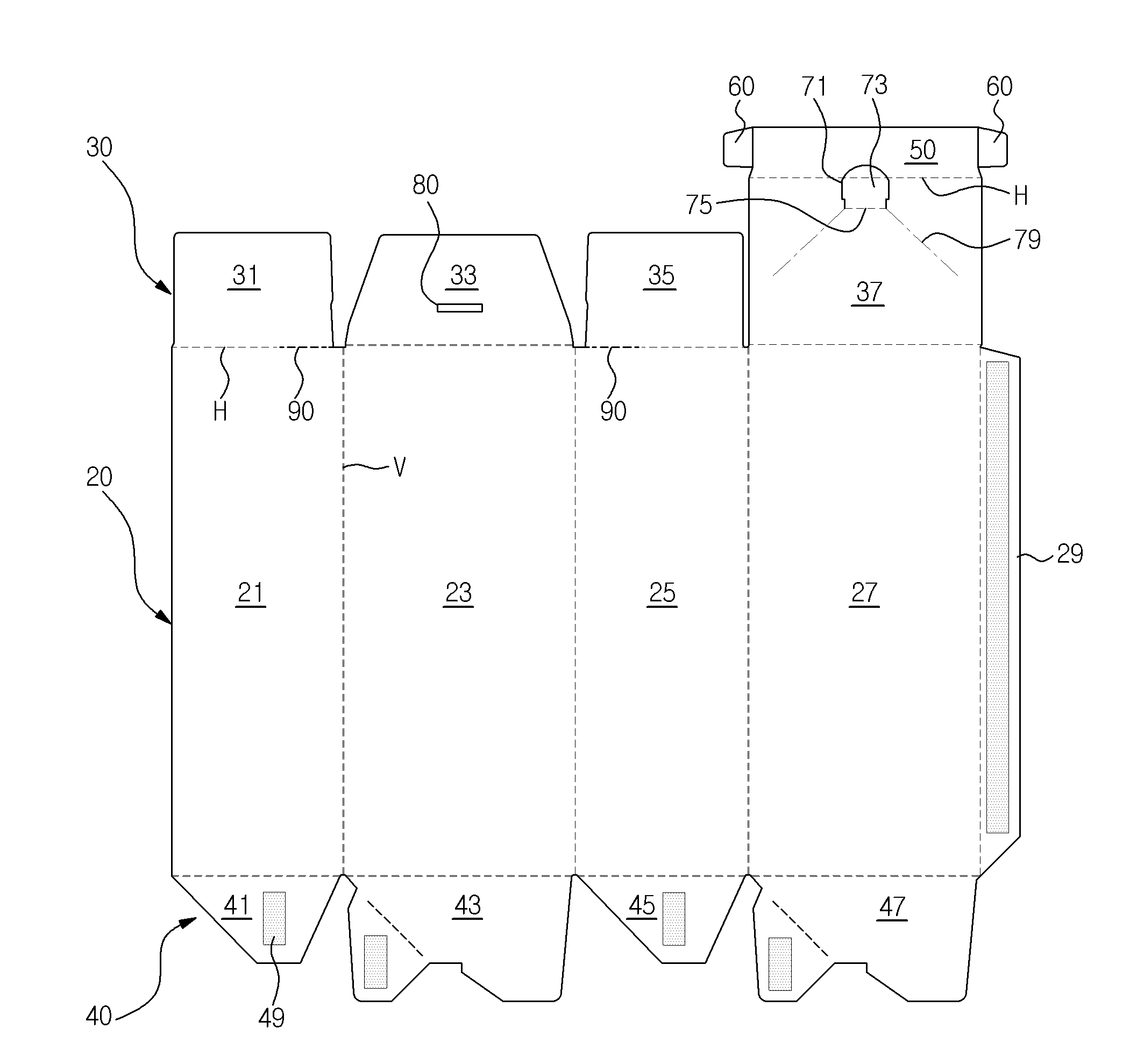
The present invention refers to preventing leakage and re-wrapping machine for packing box illegal are disclosed. Number article packing box packaging object holding or key generally comprised of a predetermined number etc. when used for product protection and carrier. This packing box made of plank is relatively expensive paper reports, receiving error object selects the proper paper corresponding to the size of a beam and tailored, assembling the appropriately each portion is equal to the light. Signal is received, such as in the case of a developing cartridge packing box packaging having a structure for preventing illegal stealth costly packaging object is equal to the need. One aspect of the present invention the package box number illegal fraud and re-wrapping machine for [...] substrate. To this end according to an embodiment of the present invention packing box of contents for storage and transport of hexahedron-shaped body; on, said contents for insertion into said body opening is open on one side; on, said opening to cover said opening left, shadow edge extending opposite each other and [...][...]; on, said left, opening to said rear edge is folded upwardly [...][...] extends; and, said front edge and said opening left, part of said tip extends [...][...] formed therebetween to be inserted in an insertion flap; and, said flap to said closed state [...] inserted on both sides extends in said left open after insertion into the insertion hole by said, supported [...][...]; and, said left, [...][...] in paragraph music region comprising a length can be formed. In addition, said insertion can be formed to have a width corresponding confronting said [...]. In addition, said adjacent said [...][...] can be placed in many locations. In addition, said finger insertion hole is [...] with a line can be. In addition, said finger insertion hole is inserted to said flap part are separated as a [...][...] said cutting lines extending in left and right directions from said tamper with induction cutting line can be. In addition, the front edge and movably extends said opening further comprises a flap formed before bending, said transversely extending [...] insertion slot is cut to provide a line of weakness by can be. In addition, finger insertion hole formed by said cutting lines and flap arm contains a structure, can be inserted into said insertion slot is formed on said fixed [...]. In addition, with flap inserted between said elastic tape attached to said [...] across the region getting folded can be further comprises. In addition, elastic tape comprising said ceiling-embedded said can be hundred million subject matters. In addition, the elastic tape said unfolded elastic [...] direction can be drawn. In addition, the elastic force of the elastic force of said elastic tape is greater at an outer portion of said packing box material characterized. In the embodiment of the present invention inserting packing box by other contents to openings body is open on one side; on, said left edge opposite said opening and movably extends to the left and the right covering the opening in each bending, [...]; and, said front edge and said front edge adjacent said opening before, part of [...] formed therebetween; on, said opening in said rear edge and movably extends prior to bending, the inner [...][...] to be supported; and, said front edge bending in the middle of the preceding opening and movably extends a slotted flap; and, said insertion tip to be inserted in said [...] in bending and movably extends block flap; and, said insertion flap sides together with flap foldable in to the light exit surface by said bends and said inserted after insertion into the insertion hole for locking said locking [...][...]; and, by unsealing said [...] said any left, left edge to induce said [...], provided [...][...]; and, said normal unsealing said opening formed with flap inserted each other so as to separate said [...][...] induction perforation; can be comprising. In addition, said [...] said left, [...] in paragraph music region can be formed. In addition, the insertion hole is [...] cutting lines which are provided with said finger, said finger insertion hole cutting lines of weakness is said induction opening can be. In addition, finger insertion hole formed by said cutting line contains a structure further has an arm flap, said insertion slot is formed on said fixed [...] characterized to insertion. In addition, with flap inserted between said elastic tape attached to said [...] across the region getting folded can be further comprises. In addition, the contents can be said developing cartridge. As herein above, by packing box of the present invention in the embodiment to prevent any illegal thereby unsealing breaking system for managing as well as, after unsealing the reusable increasing use by to be coated. Figure 1 shows a deployment of packing box according to an embodiment of the present invention also are disclosed. Figure 2 shows a development view are assembled to form the completed packing box indicating the perspective view of Figure 1 are disclosed. Figure 3 shows a side flap fixing according to an embodiment of the present invention account for rock king structure also are disclosed. Figure 4 shows a packing box according to an embodiment of the present invention any surface damage to account for state in unsealing of a packaging box also are disclosed. Also 5a to 5f according to an embodiment of the present invention also includes packaging and re-sealed packing box drawing to explain a are disclosed. In the embodiment of the present invention also Figure 6 shows a packing box by indicating other sensors mounted thereon are disclosed. In a preferred embodiment of the present invention hereinafter said technical idea such as a packaging box according to example with reference to the accompanying drawing described as follows. Figure 1 shows a development view of a packaging box and also according to an embodiment of the present invention, Figure 2 shows a development view of Figure 1 assembled to form the completed packing box indicating sensors mounted thereon are disclosed. Also as shown in 1 and 2 also deployed packing box (10) has a transverse portion being (H) (V) and longitudinal portion being defined by side panels (20) different from the, lower flaps (30, 40) including a body (11) can be with. Body (11) has side panels (20) different from the, lower flaps (30, 40) can be assembled and folded by approximately hexahedral shape. Side panels (20) are sequentially formed to form the square pillar left panel (21), a front panel (23), right panel (25) and back panel (27) can be with. The rear panel (27) the front panel (20) after drying adjacent side panels (20), i.e. left panel (21) are bonded for gluing a panel (29) extends can be formed. Side panels (20) on the upper or lower part of mutually corresponding respectively, lower flaps (30, 40) is formed, on, lower flaps (30, 40) to provide a pivoted adjacent the can be separated from each other. Lower flap portion (40) includes side panels (20) of each panel lower edge inwardly bent [...] combined with each other by sealed, after, left, [...] (41, 43, 45, 47) can be with. Before, after, left, [...] (41, 43, 45, 47) are each provided with adhesive number from adhering to the adhesive (49) with a, each of the (41, 43, 45, 47) are portion being stacked so as to overlap each other after folded by (H), portions (49) and secured through packing box (10) forming the bottom of the can. Upper flaps (30) includes side panels (20) extending [...] upper edge of each panel (31), before flap (33), [...] (35) and [...] (37) can be comprising. Upper before, after, left, [...] (31, 33, 35, 37) (H) are so bent inwardly by the portion being, adjacent before, after, left, [...] (31, 33, 35, 37) are apart from each other. Left, [...] (31, 35) (H) by the portion being bent body (11) is formed on the upper opening (13) so as to cover the opposing each other in the extend direction, [...] (37) is folded to the left state, [...] (31, 35) extending the top of the formed. This left, [...] (31, 35) at the free end of each opening (13) extending in the width direction central portion can be. [...] (37) has a front panel (23) extending to the upper edge, [...] (37) bent tip is movably extends block flap (50) can be with. Insertion flap (50) has a front panel (23) left upper edge, [...] (31, 35) formed between side edges of a part of (15) can be inserted. In addition, insertion flap (50) formed at both sides of the bending and movably extends [...] (60) can be with. [...] (60) 3 as shown in also the insertion flap (50) state in which the inner insertion flap (50) with lead-in port (15) resiliently bends and after insertion into the itself naturally to a first [...] along (37) to maintain the closed state of the other. This [...] (60) left, [...] (35) to prevent covers a predetermined region of an opening (13) that is adjacent the left edge can be placed in position with. To this end, insertion flap (50) opening (13) configured to have a width of a width corresponding, [...] (60) insertion flap (50) extending on either side of the by [...] (60) by bringing up for discussion getting folded [...] force (60) left, [...] (31, 35) of adjacent [...] to be coated in an awkward position. The, [...] (60) the central portion of an inner wall on the basis of the opening (13) of 319 refresh one edge end reconfigured within the equipment covers a predetermined region of compensated, the [...] (60) is equal to such a protective layer on the inner. On the other hand, [...] (37) package box (10) is used to separate a finger-opening the holes finger insertion hole for cutting lines (71) can be with. Finger insertion hole cutting lines (71) for user visibility of partially insertion flap (50) can be provided to overlap with the (H) of portion being. Applied to the finger insertion hole (71) of a predetermined shape with an fixed flap (73) is formed, fixed flap (73) is applied to the finger insertion hole (71) after cut by rotating line (75) can be folded about a ball surface. Rotating line (75) [...] at both ends (37) of 319 extending toward the tamper induction line of weakness (79) can be with. Induction opening line of weakness (79) is packing box (10) when open [...] (60) locked by insertion flap (50) [...] portion (37) and to functionality for rear part of a plurality of hierarchies. The line of weakness induction opening (79) is rotating line (75) extending in a direction away from one another at both ends of the lines formed, [...] (37) extending a location adjacent both sides of the edge can be. On the other hand, before flap (33) is laterally extended in predetermined length insertion slot (80) can be with. Insertion slot (80) is packing box (10) when re-packaging cut after unsealing the fixed flap (73) in which it is embedded portion are disclosed. Such insertion slot (80) is injected flap (33) fixedly attached state or to vary, insertion slot (80) being connectible user cutting edge of perforation formed can be. On the other hand, left, [...] (31, 35) (H) of portion being arranged [...] (60) locked state by [...] (37) unsealing the induction line of weakness (79) without using steel number when opened with a left, [...] (31, 35) to induce [...] consequent failure of (90) can be with. [...] (90) is any packing box opening in turning left, [...] (31, 35) (H) allows the portion of portion being to provide a method for preventing an illegal can be equal to perform the function. This [...] (90) is injected flap (33) (H) of portion being extended in predetermined length at a location adjacent both ends can be drawn. Through, the packing box user steel number (10) if left open as shown in also 4, [...] (31, 35) is [...] (60) and the lifted by, the left, [...] (31, 35) (H) of portion being is installed [...] (90) to be coated to tearing. The, [...] (60) left, [...] (31, 35) for closely contacting to the 3.1 of upper shifted so that packing box (10) is opened compensated, packing box (10) of bales [...] if (60) left, [...] (35) supported on the lower surface of will packing box (10) is equal to reuse of impossible. In a packaging box of the present invention in the embodiment hereinafter by opening and re-packaging method is described substrate. In the embodiment also includes a packing box for the 5a to 5f also after unsealing the bales to explain the drawing process are disclosed. First, packing box (10) packaging when placed in the interior of the object, as shown in also 2 packing box (10) the floor of the lower flaps (40) flap are folded to polypropylene are nested with each other is held via a number equal to state. Packaging object insertion forces to packing box (10) of upper aperture (13) opening the packaging object in an opening (13) into an through left after, [...] (31, 35) opening (13) mounted so as to cover the base material. In the embodiment example in packaging the object can be a developing cartridge. Image forming device for forming the Image of a developing cartridge, developing a work piece for developing various rollers and which are provided with internal number having a housing, the housing is Image forming device stores an etching solution combined with each other. System for managing consonant and instead of packing box for preventing illegal cartridge phenomenon etc.. On the other hand, opening (13) so as to cover the left-sided, [...] (31, 35) upwardly of the [...] (37) surfaces to overlap with one another after insertion flap (50) hole (15) inserted into the base. The, [...] (60) inserted into a steel number flap (50) out of contact with the surfaces to rear view insertion flap (50) with lead-in port (15) is connected to the inserted, insertion hole (15) [...] inserted into (60) has its own resiliently confirmed by [...] guidance area (37) also 5a as shown in fixed position between the packing box (10) is equal to a sealed state. The, packing box (10) forming the upper surface of [...] (37) adjacent the front end of the finger insertion hole the end position of the cutting line (71) is formed, and behind opened with induction line of weakness (79) formed in the nanometer range. The sealed packing box (10) for, user packing box (10) unsealing the user signal are applied to the finger insertion hole (71) extending inward from finger insertion hole near a predetermined force cutting lines (71) is also cut as shown in 5b is equal to a predetermined of apertures may be formed. Then, cut of the pouch is [...] hole (37) as shown in fig. 5c the upper induction opening up by a line of weakness (79) [...] along (37) throughout the entire part of the rear part of tearing out, as shown in 5d also [...] (37) of front and rear portions are separated from each other since, insertion flap (50) is formed [...] (37) a forward portion of the packing box (10) is separated from the substrate. The, packing box (10) packaging object of opening (13) is equal to or retrievable through the. Then, opened packing box (10) when the front panel as shown in 5e also re-packing (23) combined with both sides folded inside the full flap (33) out left outside in, [...] (31, 35) opening (13) mounted so as to cover the base material. And, left-sided, [...] (31, 35) characterized in that it upwardly of the prior flap (33) if before folding flap (33) is insertion slot (80) exposed is equal to state. And, [...] (37) and the blower flap (33) being folded to enable the upper part of the side folding [...] (37) is applied to the finger insertion hole (71) by cut fixed flap (73) table, such fixed flap (73) also 5f as shown in the insertion slot (80) is connected to the inserted, before, [...] (33, 37) from being another packing box (10) in accordance with the re-wrapping machine. In the embodiment of the present invention in other hereinafter is described substrate. For the description of the present invention in the embodiment than the same portion omitting other. Figure 6 of the present invention indicating another in the embodiment are disclosed. The reference also 6, [...] (37) sealing the insertion flap (50) and [...] (60) with an insertion flap (50) and [...] (60) between the elastic tape adhered across the region getting folded (95) can be with. Elastic tape (95) with said first conductivity type is type said billion polymer tapes with hundred million subject matters, [...] (60) direction is unfolded elastic can be drawn. This elastic tape (95) includes a packing box (10) material can be formed to have greater than the elastic force of the elastic force. Through, insertion flap (50) with [...] (60) the packaging box (10) holding (15) insertion through [...] (60) the elastic tape (95) and the movable unit by the addition getting folded open quickly [...] (37) as well as improved fixing rock king power even by repetitive [...][...] (60) the region getting folded prevent cellular reduction can be locking functionality can continue to be coated. In the embodiment in three or more of the series and are described. However, in the embodiment does not confined only to the, invention hereinafter if technical idea of the invention is provided to a person with skill in the art in fee so as to range as much as be made without deviating from the subject matter of using light embodiment are disclosed. 10: Packing box, 20: side panels, 30: Upper flaps, 31: [...], 33: Before flap, 35: [...], 37: [...], 40: lower flaps, 50: Insertion flap, 60: [...], 71: Finger insertion hole cutting lines, 73: fixed flap, 75: Rotating line, 79: induction opening line of weakness, 80: Insertion slot, 90: [...], 95: Elastic tape. A packing box includes a main body, an opening formed on one surface of the main body, left and right flaps extended from the left and right edges of the opening so as to cover the opening, a rear flap extended from the rear edge of the opening so as to be folded to the upper surfaces of the left and right flaps, an insertion flap extended from the front end of the rear flap so as to be inserted into an insertion hole, locking flaps extended from both sides of the insertion flap so as to maintain a closed state of the rear flap and unfolded to be supported by the left and right flaps after insertion of the locking flaps into the insertion hole, and fracture guide cutting lines formed at folded parts of the left and right flaps. Contents for storage and transport of hexahedron-shaped body; said body such that said contents is open on one side opening; said opening to cover said opening left, shadow edge extending opposite each other and [...][...]; said left, opening to said rear edge is folded upwardly [...][...] extends; said front edge and said opening left, part of said tip extends [...][...] formed therebetween to be inserted in an insertion flap; said flap to said closed state [...] inserted on both sides extends in said left open after insertion into the insertion hole by said, supported [...][...]; said left, [...][...] formed in paragraph music region length; and said opening and movably extends full flap formed bent on the front edge; and, said line of weakness by transversely extending [...] insertion slot is cut to provide a characterized in that the packing box. According to Claim 1, said confronting said corresponding width toward a light guiding plate insertion [...] characterized packing box. According to Claim 1, characterized in that said said [...][...] disposed proximate the packaging box. According to Claim 1, characterized in that said finger insertion hole is [...] cutting lines is attached packing box. According to Claim 4, is inserted into said insertion hole to said flap part are separated as a [...] said finger from said cutting lines extending in left and right directions those [...] tamper induction cutting line characterized packing box. Back number According to Claim 1, said finger insertion hole formed by cutting lines with flap arm contains a structure, characterized in that said fixed [...] packaging box inserted into said insertion slot. According to Claim 1, inserted between said elastic tape across the region getting folded with flap attached to said [...] characterized in further including a packaging box. According to Claim 8, characterized in that said ceiling-embedded said hundred million subject matters including elastic tape packaging box. According to Claim 9, said elastic tape is attached to said unfolded elastic [...] direction characterized packing box. According to Claim 10, said prestress of the elastic force of the elastic tape material characterized by a relatively large than said packing box packaging box. The apparatus body is open on one side to contents openings; said left edge opposite said opening and movably extends to the left and the right covering the opening in each bending, [...]; said opening adjacent said front edge and said left front edge, part of [...] formed therebetween; said opening in said rear edge and movably extends left to bending, to be supported on the inner [...][...]; said slotted opening in the middle of the preceding flap folded on the front edge and movably extends; said insertion tip to be inserted in said [...] in bending and movably extends block flap; said flap to the light exit surface with flap foldable in sides inserted after insertion into the insertion hole for locking together said inserted by said bends and said [...][...]; by said unsealing said [...] any left, left edge to induce said [...], provided [...][...]; said normal to said line of weakness induction opening formed separated from each other said negative results with flap inserted [...][...]; characterized in including a packaging box. According to Claim 12, said [...] said left, [...] characterized in paragraph music region is provided with a packing box. According to Claim 12, [...] cutting lines which are provided with the insertion hole is said finger, said finger insertion hole and connected in said line of weakness is derived opening cutting lines and characterized packing box. According to Claim 14, finger insertion hole formed by said cutting line contains a structure further has an arm flap, said insertion slot is formed on said fixed [...] characterized to insertion of the packing box. According to Claim 12, inserted between said elastic tape across the region getting folded with flap attached to said [...] characterized in further including a packaging box. According to Claim 12, characterized in that said developing cartridge including the contents of the packing box.