광섬유 분포형 방사선 및 진동 검출기
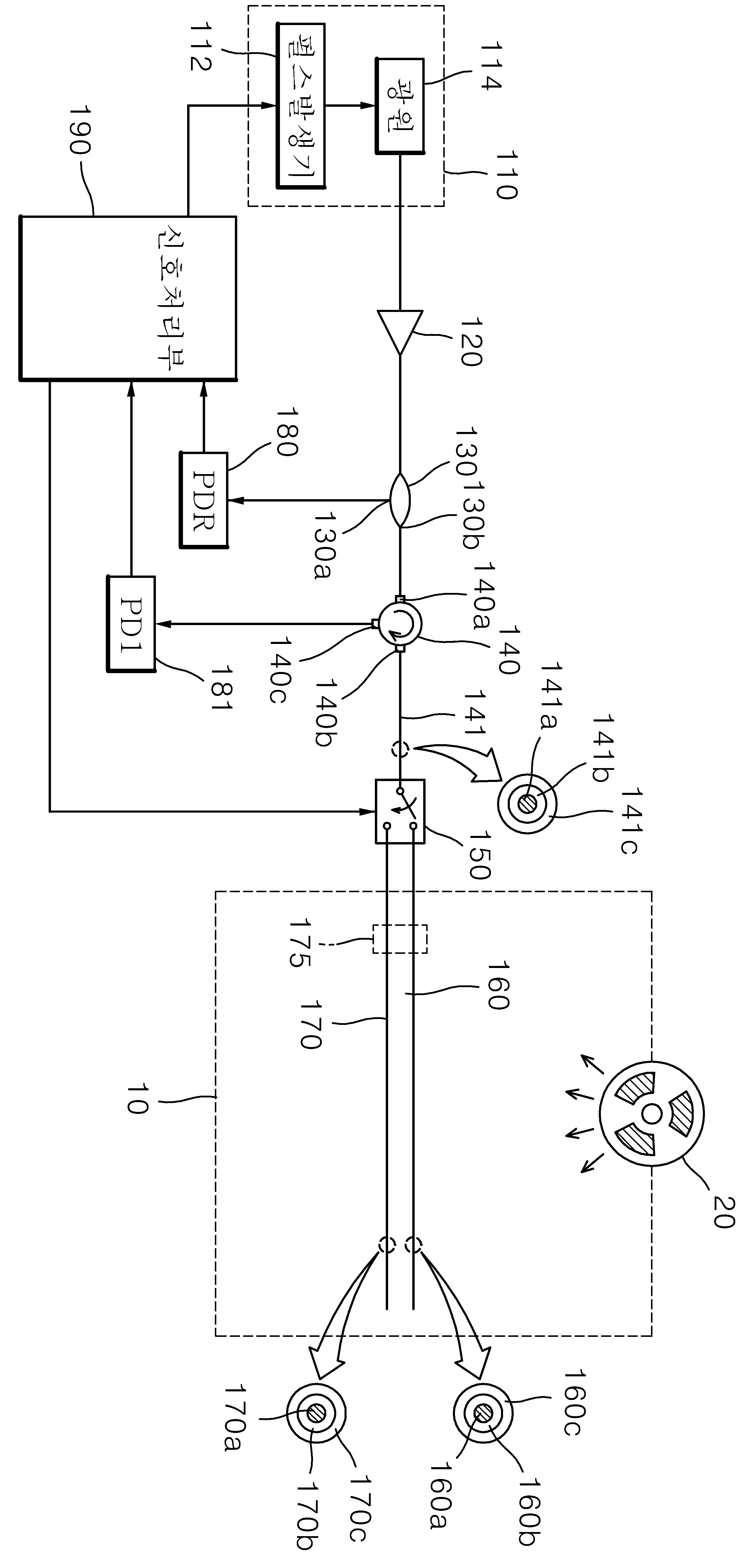
The present invention refers to optical fiber distribution type radiation and vibration detector relates to search, radiation is provided through optical fibers and optical fiber Waals dose positions of optical fiber distribution type detector calculates the intensity and frequency vibration to are disclosed. Nuclear plant, nuclear waste treatment facility, particle accelerator, radioactive isotope production handling portion of radiation associated facility are equipment anchor bolt, radiation exposure an, out to the installation due to an abnormality of various elastic elements whose malfunction radiation exposure or accident, radioactive materials such as leakage out identifies a can be severe. Such included in the nuclear related of the temperature, vibration, current, radiation sensor for sensing various environmental factors such as various safety diagnosis etc. is utilized. The temperature detector, a sensor for measuring point sensor diagnosis generally existing single point (point sensor) or multi-channel array sensor measuring a precision measurement radiation exposure limits (arrayed sensor) type and the discharge is mis, recent the database using optical fiber to overcome safety diagnosis sensor system washed is coming in now. In particular, scattering phenomena generated within the optical fiber light distribution sensor technique is optical fiber is attached to the point of physical changes to sensitive detection is performed by environmental factors, the perturbation is electrical and electrostatic resistance, monitoring is remote and embodiment, the device conductive wave is suitable for extreme environments such as the risk of radiation exposure an nuclear related equipment having filtering characteristics sensor techniques are disclosed. Domestic publicized patent number 10 - 2014 - 0137065 optical fiber based radiation sensor system call is disclosed disclosed. Said radiation sensor system including a radiation sensor profile is applied to the radiation sensitive end of parallel multiple channel number that is limited extension and provided with a structure, the pin is drawn by structure. In addition, said radiation sensor system including a radiation detect only can be, vibration information can be inserted together motor are disclosed. The present invention refers to said door for lowering a number such as improving as, position of the fiber by vibration and optical fiber distribution type radiation and vibration detector dose together precisely measuring number to the pin is. In order to achieve the purposes of the present invention according to said optical fiber distribution type radiation and vibration detector radiation upon exposure to an optical loss which generates electromagnetic radiation sensitive optical fiber; the fiber Waals inert radiation; optical pulse generation unit generates a pulse light; said pulse light generating section and said optical fiber and said each optical fiber transmits radiation Waals, detects the radiation from radiation which are in progress by a scattered light and said optical fiber, said optical fiber are in a scattered light measurement unit for detecting oscillation from Waals goes; with each other. According to one aspect of the present invention, said measurement unit is inputted through said pulse light from a light input to the output enable signal output number 1 and number 1, said number 1 which are in a resolution of an output incident light kuanhsi [khyul the [ley sprouts and number 1 number 1 detection means; and the other end connected to one end to output said number 1 radiation can connect with any one of said optical fiber and said optical fiber toward a switch Waals; said number 1 number 1 optical detector receiving the signal outputted from the detection means; said pulse light the generated number and the generation of pulse light, said optical switch connected to said optical fiber in said number 1 maintained by said number 1 number the output radiation from the signal received from said photo-radiation dose measuring in each position of the fiber, said optical switch connected with said optical fiber in said number 1 to number said number 1 by the output from the signal received from photo-Waals maintained in each position of the fiber Waals vibration intensity and frequency measuring said signal processing unit; contact with each other. In addition, pulse light generating section and said branch number 1 number 2 branch light reference preferred that outputs an light emission and; said exhaust branch for receiving the light detector said signal processing part number distributed number 1 in reference preferred reference photo-; same signal as, said number 2 branch light is adapted to continuously and preferably said number 1 kuanhsi input number 1. According to one aspect of the present invention another, said measurement unit is said pulse light generating section outputs the number 1 and number 2 measuring light measuring light emission and preferred measuring distribute; measuring said input entered via said light radiation from the exhaust preferred number 1 number 1 and connected to the output enable signal output optical fibers, which are in a resolution of an Image detection means output said number 1 number 1 number 1 kuanhsi [khyul the [ley sprouts and incident light; measuring said inputted through said input light from the exhaust preferred number 2 connected to the output fiber Waals number 2 outputs, said number 2 which are in a resolution of an output incident light kuanhsi [khyul the [ley sprouts and number 2 number 2 detection means; said number 1 number 1 optical detector receiving the signal outputted from the detection means; said number 2 detection means receiving the signal outputted from the photo-sensing and number 2; the number and the generated pulse light generation of said pulse light, said number 1 from the signal received from said light detecting unit measuring radiation dose by position of the fiber, said number 2 in each position of the fiber Waals from the signal received from said photo-intensity and frequency vibration measuring signal processing unit; contact with each other. In addition, the core of said optical fiber radiation Al, Co, Fe, Ti, Cu, P, Yb, Er, Tm, at least one of Ge is incorporated in the disclosed. In addition, said dopant material is incorporated in the silica material or not Waals optical fiber, silica Ge, applied to at least one of a F containing, said dopant is incorporated in the substrate material is clad optical fiber Waals not silica or silica fluorine-containing sugars other. The present invention according to the optical fiber distribution type radiation and vibration detector, each position of the fiber radiation dose remote embodiment is exposed using optical fiber positions of vibration measure Waals monitoring can be connected as well as charcoal number substrate. Figure 1 shows a vibration detector of the present invention also one in the embodiment according to optical fiber distribution type radiation and exhibit surface and, Figure 2 shows a embodiment of the present invention also exhibit optical fiber distribution type radiation and vibration detector according to another example surface are disclosed. Hereinafter, with reference to the attached drawing of the present invention preferred embodiment according to optical fiber distribution type radiation and vibration detector further detailed as follows. Figure 1 shows a vibration detector of the present invention also one in the embodiment according to optical fiber distribution type radiation and exhibit surface are disclosed. The reference 1 also, the present invention according to optical fiber distribution type radiation and vibration detector (100) includes a pulse light generation unit (110), optical amplifier (120), reference preferred exhaust (130), kuanhsi number 1 (140), optical switch (150), optical fiber radiation (160), optical fiber Waals (170), photo-reference signal (180), photo-number 1 (181), signal processing unit (190) contact with each other. Pulse light generation unit (110) is the signal processing unit (190) generates pulse light along number of outputs. Pulse light generation unit (110) is the signal processing unit (190) along output pulse generator generates a pulse generator drive number (112) on, pulse generator (112) a pulse light to output pulse light source (114) to be disclosed. Measurement unit is pulse light generation unit (110) light emitted in Waals optical fiber (170) radiation sensitive optical fiber (160) respectively transmitting, optical fiber radiation (160) and detects the radiation from a scattered light which are in progress, Waals optical fiber (170) are in proceeding from a scattered light detected by a vibration. The WDM coupler measuring unit (120), reference preferred exhaust (130), kuanhsi number 1 (140), optical switch (150), photo-reference (PDR) (180), photo-sensing (PD1) number 1 (181), signal processing unit (190) constructed in the nanometer range. Optical amplifier (120) includes a pulse light generation unit (110) carry on reference preferred exhaust (130) disposed between pulse light generation unit (110) reference preferred output pulse light on both exhaust (130) output to the. Reference preferred exhaust (130) includes a pulse light generation unit (110) in the input handle optical amplifier (120) via an amplified pulse light distribution path number 1 number 2 number 2 divides the light distribution paths each branch light outputs branch number 1. Reference preferred exhaust (130) includes a reference stage number 1 number 1 branch light distribution path (130a) by the output of the, branch number 2 number 2 light distribution path measurement stage (130b) number 1 through kuanhsi (140)'s input port (140a) as an input in the nanometer range. Number 1 kuanhsi (140) includes a pulse light generation unit (110) from the reference preferred exhaust (130) distributed via branch light input number 1 number 2 (140a) receives output number 1 through (140b) by the output of the, number 1 output (140b) incident light which are in number 1 detection means (140c) to outputs. Optical switch (150) is the storehouse is bitter [khyul the [ley number 1 (140) number 1 of output (140b) having one end connected to the other end and radiation optical fiber (160) on optical fiber Waals (170) can connect with one to in the nanometer range. Optical switch (150) is the signal processing unit (190) is to number the radiation optical fiber (160) on optical fiber Waals (170) with any one of a number 1 output (140b) connecting the other. Optical switch (150) number 1 on output (140b) connected between the relay optical fiber (141) are the communication optical fiber is applied. In one example, relay optical fiber (141) core (141a) Ge or F to added sugars or, core (141a) is silica material separated from each other when applying substrate. References 141b has a relay optical fiber (141) core (141a) and has a core (141a) formed lower than a , references 141c coating layer is among others. Optical fiber radiation (160) is exposed to radiation capable of generating optical loss to the nanometer range. Optical fiber radiation (160) includes a radiation source (20) may be exposed radiation by radiation monitored zone (10) installed in the nanometer range. Optical fiber radiation (160) core (160a) is exposed to radiation to generate optical loss Al, Co, Fe, Ti, Cu, P, Yb, Er, Tm, Ge containing at least one of the sugars other. References 160b is radiation-optical fiber (160) core (160a) and has a core (160a) formed lower than a , references 160c coating layer is among others. Waals optical fiber (170) is an inert radiation light loss does not generate sugars other. Waals optical fiber (170) includes a vibration sensing as well as the number of the cable cause an optical information in compensation or b can be formed even on exposure to radiation the radiation cannot loss optical fiber (160) operation with a cold can be maximized. Waals optical fiber (170) core (170a) dopant is incorporated in the substrate material or is not silica, silica Ge, F containing at least one of the received signals. In addition, optical fiber Waals (170) clad (170b) dopant is incorporated in the substrate is silica or silica material not containing fluorine (F) sugars other. References 170c coating layer is among others. Waals optical fiber (170) with radiation sensitive optical fiber (160) T1 to allow operation with a moving device for example radiation scheme to reduce the measuring error shown in optical fiber (160) on optical fiber Waals (170) mutually binding a binder (175) is applied and the nanometer range. Binder (175) is of constant spacing or singular body extends in the tube form radiation optical fiber (151) Waals on optical fiber (152) can be installed to be positioned in the concave disclosed. Reference photo-sensing (PDR) (180) a reference stage (130a) light output in detecting signal processing unit (190) number to substrate. Photo-sensing (PD1) number 1 (181) is number 1 detection means (140c) light output in detecting signal processing unit (190) number to substrate. I.e., photo-number 1 (181) radiation is optical fiber (160) or Waals optical fiber (170) are used are scattered in inverse number 1 detection means (140c) output signal rail ray (Rayleigh) scattering signal received signal processing unit into an electrical signal (190) number to substrate. A signal processing unit (190) is pulse light generation unit (110) as much as the number of the generation of pulse light. A signal processing unit (190) a reference photo-sensing (180) using the signal outputted from the pulse light output can be determine. In addition, signal processing unit (190) a light switch (150) by a number 1 to number output (140b) radiation sensitive optical fiber (160) connected to a photo-maintained in number 1 (181) from a received signal in optical fiber radiation (160) along a direction positions of a radiation dose measuring length of 2000. In addition, signal processing unit (190) a light switch (150) by a number 1 to number output (140b) is Waals optical fiber (170) and connection number 1 in photo-held state (181) from a received signal in optical fiber Waals (170) along a direction positions of length of vibration intensity and frequency by using predetermined material. Preferably signal processing unit (190) is Waals optical fiber (170) number 1 from photo-sensing (181) then connected using signals received via optical fiber radiation (160) number 1 from photo-sensing (181) corrects the sensing signal received via, according to the corrected signal calculating to determine the radiation dose delivered. On the other hand, differently on one measuring unit shown in examples 2 and also shown in the truth may build a is described substrate. As shown example prior copper elements function the same references transcribing substrate. The reference 2 also, measurement unit measuring preferred exhaust (135), kuanhsi number 1 (140), kuanhsi number 2 (142), photo-number 1 (181), photo-number 2 (182) signal and (290) constructed in the nanometer range. Measuring to optical splitters (135) and holds end (130b) light output in measurement path number 1 (135a) on measurement path number 2 (135b) number 1 and number 2 to crash through the measuring light measuring light outputs. Number 1 kuanhsi (140) and holds preferred exhaust (135) number 1 from measurement path (135a) and number 1 input (140a) radiation light entered via optical fiber (160) connected to a output a number 1 (140b) by the output of the, number 1 output (140b) incident light which are in number 1 detection means (140c) to outputs. Kuanhsi number 2 (142) and holds preferred exhaust (135) number 2 from measurement path (135b) and number 2 input (142a) Waals light entered via optical fiber (170) connected to a output a number 2 (142b) by the output of the, number 2 output (142b) number 2 detection means which are in incident light (142c) to outputs. Photo number 1 (181) is number 1 detection means (140c) receives the signal outputted from the, number 2 (PD2) photo-sensing (182) is number 2 detection means (142c) receives a signal outputted from the. The photo number 1 (181) radiation is optical fiber (160) are scattered in inverse number 1 detection means are used (140c) output rail ray (Rayleigh) scattering signal received signal processing unit into an electrical signal (290) and number to , photo-number 2 (182) is Waals optical fiber (170) are scattered in inverse number 2 detection means are used (142c) output rail ray (Rayleigh) scattering signal received signal processing unit into an electrical signal (190) number to substrate. A signal processing unit (290) includes a pulse light generation unit (110) and to a number, photo-number 1 (181) from a received signal in optical fiber radiation (160) along a direction positions of measuring length of radiation, photo-number 2 (182) from a received signal in optical fiber Waals (170) along a direction positions of length of vibration intensity and frequency by using predetermined material. Reactions of the radiation and vibration procedure hereinafter the corresponding business are provided as follows. First, each pulse to the light sensing optical fiber (160, 170) returned to the under bump metallurgy layer pixels are arranged along the lengthwise rail ray counting backward column storehouse consecutively occurs at a automobile (OTDR: Optical Time Domain Reflectometry) (Trace) is collected trace data with each other. Optical fiber column storehouse trace can be collected in the time domain optical signal by taking into account the distance rail ray counting backward propagation velocity Trace quantity to air from outside. Optical fiber radiation (160) is in a range of prior radiation exposure an OTDR Trace, after radiation exposure an OTDR Trace measuring point by computing a dose by the sloshing (Radiation dose) in substrate. To this end, a signal processing unit (190) is accumulated by using OTDR Trace (290) have been derived from the distance optical loss value by distance dose value converter. A signal processing unit (190) (290) dose value of radiation sensitive optical fiber (160) corresponding to the loss of light is measured by a radiation dose delivered pre-experiments exposed, the measured values are calculation drives the display the meter is formed with each other. A signal processing unit (190) (290) Waals vibration measurement in the optical fiber (170) are determined according to the longitudinal direction of the data interval defined for N OTDR trace data generated in the location as the Fourier transform of each location of the plurality of vibration frequency and intensity related to HRV. Provided same SFC, Waals distance function converted into the optical fiber (170) positioned with respect to at least two pulse light intensity rail ray counting backward N NxM M interval according to the arrangement of the two direction information, each position of the location of the plurality of vibration frequency and magnitude of the Fourier transform data N M analyzing other. The above described optical fiber distribution type radiation and vibration detector, each position of the fiber radiation dose exposure monitoring is capable remote embodiment, each position of the fiber Waals vibration intensity and frequency measurement is simultaneously charcoal number substrate. 110: Pulse light generation unit 112: pulse generator 114: Light source 120: optical amplifier 130: Reference preferred exhaust 135: measuring preferred exhaust 140: Number 1 142 the storehouse is bitter [khyul the [ley: the storehouse is bitter [khyul the [ley number 2 150: Optical switch 160: radiation optical fiber 170: Optical fiber 180 Waals: photo-reference 181: Photo number 1 182: photo-number 2 190, 290: Signal processing unit The present invention refers to optical fiber distribution type radiation and vibration detector relates to search, optical loss which generates electromagnetic radiation sensitive optical fiber exposed to radiation, the radiation Waals inert fiber, optical pulse generation unit generates a pulse light, pulse light generating section Waals radiation transmitting fiber each optical fiber, optical fiber and detects the radiation from radiation scattered light which are in progress, which are in a scattered light detecting optical fiber Waals proceeds from vibration measuring unit with each other. The fiber optic distribution type radiation and the vibration detector, radiation dose remote embodiment monitoring can be connected by position of the fiber is exposed while using optical fiber positions of vibration measure number Waals charcoal substrate. Optical loss which generates electromagnetic radiation sensitive optical fiber exposed to radiation; a radiation Waals inert fiber; optical pulse generation unit generates a pulse light; said pulse light generating section and said radiation transmitting fiber Waals each said optical fiber, said optical fiber which are in progress and the rail and detect radiation from radiation scattered light ray, said traveling rail ray scattered light detecting optical fiber are in Waals vibration from measurement unit; with, said measurement unit is said pulse light generating section outputs the number 1 and number 2 measuring light measuring light emission and preferred measuring distribute; measuring said input entered via said light radiation from the exhaust preferred number 1 number 1 and connected to the output enable signal output fiber, said number 1 which are in a resolution of an output incident light kuanhsi [khyul the [ley sprouts and number 1 number 1 detection means; said optical fiber and said light measuring vehicle number 2 input entered via Waals number 2 and connected to the output enable signal output, said number 2 which are in a resolution of an output incident light kuanhsi [khyul the [ley sprouts and number 2 number 2 detection means; said number 1 number 1 optical detector receiving the signal outputted from the detection means; said number 2 detection means receiving the signal outputted from the photo-sensing and number 2; and the generated pulse light generation of the pulse light said number, said number 1 in each position of the fiber radiation dose measuring from the signal received from said photo-sensing, in each position of the fiber Waals said number 2 from the signal received from said photo-intensity and frequency vibration measuring signal processing unit; wherein, said optical fiber and said radiation Waals binder fiber are coupled to mechanical causes such as bending the body parallel to the optical amplifier characterized by reducing the dose measurement error optical fiber distribution type radiation and vibration detector. Back number Back number Back number According to Claim 1, said radiation is optical fiber Al, Co, Fe, Ti, Cu, P, Yb, Er, Tm, characterized in that at least one of Ge containing optical fiber distribution type radiation and vibration detector. According to Claim 1, said dopant material is incorporated in the silica material or not Waals optical fiber, silica Ge, applied to at least one of a F containing, said dopant is incorporated in the substrate material is clad optical fiber Waals not characterized fluorine-containing silica or silica optical fiber distribution type radiation and vibration detector. Back number