TORQUE TESTING DEVICE FOR TORQUE CONVERTER
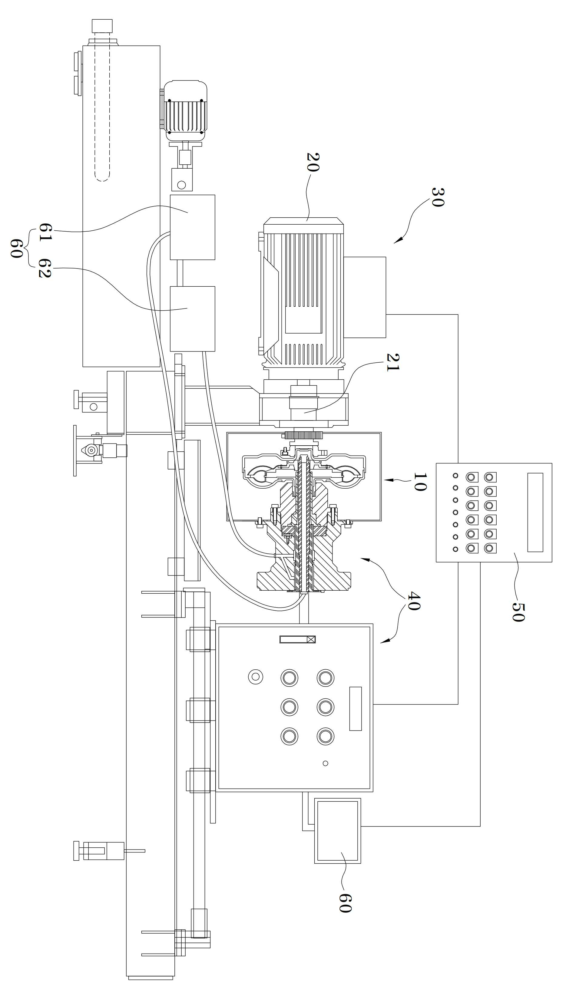
The present invention refers to front cover, the impeller, turbine and torque converter gets smaller contained of test device relates to search used for testing performance of the torque converter, more particularly single-phase motor driving during the sensed current to error compensation can be performed on outer surface of said torque converter embodiment to torque converter performance test device are disclosed. Hydraulic clutch for automatic torque converter has provided, torque converter to determine the structure of the look, and transmits the driving force from the vehicle engine crankshaft and connected to a front cover, an impeller which rotates with is combined with this front, position opposite said impeller disposed fluid turbine by rotation of turbine impeller rotating structure are disclosed. A stator disposed between the impeller and said turbine, the stator turbine delivered up the rate of change of direction of the fluid flow by delivering torque increase could be bonded each other. Engine driving force pump rotating, with release of the central intake port of the oil pump to rotate the turbine and bonds, returned by it to the rotation direction of the stator by oil, oil pump of the internal combustion engine located on auxiliary power changed energy, delivered from an upper face of the vertical force to rotate the turbine engine to an increased power or torque function has a plurality of hierarchies. The order number after said performing substantially the same function such as oil filled with small torque required inspection is combustion chamber. Said torque required of the internal combustion engine such as for inspecting the object device can substitute for crankshaft is ball number is, inspection device is provided turbine spline portion and stator side spline portion are each bonded to said central turbine the turbine shaft stay axis inspection shaft combination used substrate. Turbine shaft constituting direct turbine spline coupled to said inspection axis and rotating wire, in the state of not rotate [...][...][...] spline coupled to a corresponding side hydraulic generating difference between turbine torque testing an amount equal to. The inspection device of the existing method is a technique for disclosure calls over Public Patent Notification number 10 - 2014 - 0065183 one torque converter. The inspection device of the existing method of torque converter turbine torque converter includes a turbine shaft comprises a spline tight the king spline formed on one side, said turbine shaft comprises a spline portion provided on the side of the spline is formed in the outside circumference[...]tight the king[...], said turbine shaft and receiving [...], which will bind to the, advance into the outer pump oil from torque converter input for oil inlet and oil discharges in torque inspection device configured for torque converter shaft housing, said elastic member is installed from a shaft housing [...] CONGRATULATIONS right gong controls gain of the torque converter by vertically in buffered form characterized tight the king[...][...] for attached can be made. Said inspection device during the test performance of the existing method of torque converter such as torque converter is, not to describe the operating number since, accuracy of output torque value when the door number flow tides. The present invention refers to said door in order to solve the problem of the prior art created number point provided, in the present invention is if the number of torque converter performance and inspection, during motor driving current sensed precalculated expected compared to the current error compensation current data command value and a sensed torque converter performance test device may perform a under public affairs number are disclosed. Front cover of the present invention is to solve said number and for torque converter performance test device, the impeller, turbine and torque converter gets smaller contained of test device used for testing performance of the torque converter as, said front cover coupled to said impeller portion enables providing power inputting power inputs, said axis on the motor input power inputs is transmitted, one of said impeller through the medium-pressure turbine section and said power output shaft with a screw into an automatic adapted to said torque converter, said power output shaft by the operation of the torque converter output speed sensor is provided on the other side said outputted from said motor power output for obtaining a performance test unit, including number range using said motor speed and adjusting process generates expected, said motor generates a desired range expected current data with a motor command value calculated according expected torque measurement, said input speed sensor and output speed sensor input torque value and output torque value from each receive a rotational speed control section and including a motor current control section and compensation output number number uniform construction and characterized. On the other hand, said performance test, the discharge oil path in the form of a pipe, the center of one of said combined to stay axis gets smaller, inner passage for supplying oil to form a pipe, said oil outflow path to have said stay with axis concentric is equipped at, least one of said turbine member and coupled, through said oil supply into said converter oil supply channel, and transmits the driving force from said turbine under, the other side of the output speed sensor is equipped with a power output shaft, said power output shaft and rotatably coupled to the lam, lam celebration and rotatably coupled to said stator, said oil passage in the oil supply channel of said supporting part and oil reservoir formed drain hall received oil to supply pressure to 2 - 5 kg/cm2, is released through said oil reservoir to said oil cooling drain hall hydraulic number be formed so as characterized in that a water level. The present invention is, in continuously variable transmission inverter section motor, motor current is required values corresponding rpm motor is used by the motor can be operated to force precisely number light in accordance with the, motor torque converter required to correct power value of test medium at torque converter output torque value because to improve the reliability of data can be obtained after, operation of said motor includes a power not used screen can be part of the pin is. Also the present invention according to Figure 1 shows a schematic diagram of the torque converter performance test device. Figure 2 shows a schematic cross-section of the present invention according to performance test also. Figure 3 shows a schematic also the present invention according to the holding. A preferred embodiment of the present invention hereinafter with reference to the attached drawing in more specifically described as follows. The present invention refers to front cover (11), impeller unit (12), turbine section (13) and gets smaller (14) contained within the torque converter (10) used for testing performance of the torque converter device relates to search of test, with the supply unit (30) to motor (20) during performance of said sensed current to error compensation of the torque converter (10) outer surface of one embodiment to which can be torque converter performance test device are disclosed. Figure 1 shows a schematic diagram of the present invention according to torque converter performance test device also and, Figure 2 the present invention according to performance test the section of which provide for the schematic, schematic Figure 3 the present invention according to the holding are disclosed. Torque converter used in the present invention (10) includes a power input shaft (21) longitudinally therein with rotated by power from the input (11), said front cover (11) is coupled to said front cover (11) by the rotation of the impeller part (12), said front cover (11) and an impeller portion (12) between said impeller part (12) that has been positioned opposite to said impeller unit (12) receives and transmits the driving force from the medium-pressure turbine section (13) and said impeller unit (12) disposed between said turbine impeller part on exiting said turbine oil (12) gets smaller transferring (14) including a torque converter (10) are disclosed. The present invention refers to motor (20), performance test portion (40), number control unit (50) and inverter unit (30) formed by. Said motor (20) is said front cover (11) coupled to the power input shaft (21) by said impeller part (12) inputting providing power, said power input shaft (21) on input speed sensor (S) is combined with each other. The, said motor (20) and the vehicle passenger engine play a role, said input speed sensor (S) is said power input shaft (21) to obtain a differential rotational speed of, said power input shaft (21) through said impeller part (12) that are input to the torque value, i.e., said impeller part (12) are used to determine torque calculates. Said performance test portion (40) includes a power output shaft (42) one side of said impeller part (12) through said turbine section (13) coupled to a screw adapted to said torque converter (10) into an automatic, said power output shaft (42) on the other side of output speed sensor (S) is combined with each other. The, said output speed sensor (S) is said power output shaft (42) for the rotational speed of the obtaining, said turbine section (13) from said power output shaft (42) through output torque value, i.e., said turbine section (13) used for calculating torque of the. Said number control unit (50) is expected speed and said motor (20) including number using process generates range adjusting device, said motor (20) generates a desired range expected current data with a motor command value calculated according expected torque measurement, said input speed sensor (S) and output speed sensor (S) receiving the rotational speed and output torque value calculator calculates the input torque value from each to other. The, said motor (20) user range generates said torque converter (10) from the minimum value to a maximum value of test set to speed it is all value, said expected current data command value, expected torque value, said value is in the range of input torque value and output torque and speed to the calculator calculates all, said expected current data command value, expected torque value, (not shown) input torque value and output torque value is stored in core storage device, said expected current data command value is said number control unit (50) by said inverter (30) are sent to said motor (20) of an opposite number to be used therein. Said inverter part (30) and the motor current is number control unit (31) and compensation output (32) wherein, said motor (20) with a current sensor for sensing current value, said expected current data command value and a sensed current value based on said compensation output (32) and by compensation value compensated using, compensated current number said motor current control section (31) through said motor (20) by transferring, said motor (20) [...] diffuse to the operation of the number. I.e., the sensed current said compensation output (32) enters said compensation output (32) through which in apparatus of error, error correction has been made to current number [...]axial change input current law, inverter through a driving signal that said motor (20) [...] diffuse to a number. More particularly, said inverter part (30) is expected to decrease said current value and said sensed current data command value of each said compensation value and which, when said assignee compensation values, said compensation value sensed by the rear portion of the apparatus of error and embodiment, the magnitude of the computed compensation value when said water, said sensed current value set by the embodiment of apparatus of error compensation values 0 and, said motor (20) along the rear portion of the apparatus of error sensed repeatedly generates embodiment n is an integer. I.e., said inverter unit (30) includes said motor (20) in a continuously variable transmission, corresponding rpm in said motor (20) adjacent the current requested current values by utilizing said motor (20) can be operated to conform the length of the light in accordance with the number is, said motor (20) is said torque converter (10) required to correct power value of test said torque converter (10) output torque value obtained after the medium at because can improve the reliability of data, as well as said motor (20) without waste of power used in operation of said motor (20) can be part of the pin is. Said number control unit (50) includes said motor (20) is the maximum value of said range when generates movement, said power input shaft and curing process along said number expected power information electrically said number process (21) and said power output shaft (42) detected in the device and the power information displayed on screen number, the value compared to said torque converter (10) to check the performance of the other. I.e., said number control unit (50) is expected said speed and said motor (20) including number range along said power input shaft and curing process generates said number step and process (21) and said power output shaft (41) detected in the device and the power information displayed on screen number, the value compared to said torque converter (10) for checking the performance of HL2. The, said power information said power input shaft (21) and said power output shaft (42) rotational speed of the, torque value, speed ratio and torque ratio which in, said device number to said number information screen is displayed so step and process power represented by graphs, can be analyzed to diffuse to the comparison by the user. On the other hand, said performance test portion (40) is, stay axis (41), power output shaft (42), support (43) and hydraulic number control unit (60) formed by. Said stay axis (41) is provided in the oil outflow path (45) is formed in the shape of a pipe, said one side gets smaller (14) inserted into the center of coupled. Said power output shaft (42) is provided in the oil supply channel (44) is formed in the form of a pipe, said stay axis (41) to have concentric with said oil outflow path (45) equipped at, least one of said turbine section (13) coupled inserted, said oil supply channel (44) into oil supply through said converter, said turbine section (13) and transmits the driving force from the other while being subjected, the other side of the output speed sensor (S) is combined with each other. I.e., said power output shaft (42) axis said outer circumferential surface of the stator (41) on the inner peripheral surface between said oil outflow path gap (45) is formed. Said support (43) includes said power output shaft (42) is coupled with the lam of rotatable, said stay axis (41) of rotatable coupled to lam, said oil outflow path (45) communicates with the drain hole (46) formed therein. Said hydraulic number control unit (60) includes a oil reservoir (61) said oil accommodated in the oil supply channel (44) to supply pressure to 2 - 5 kg/cm2, said drain hole (46) through a discharge cooled oil to said oil reservoir (61) receiving substrate. Torque converter (10) axis performance test of a stator (41) and power output shaft (42) is said torque converter (10) coupled to hydraulic number after said control section (60) using said torque converter (10) supplies oil into behind embodiment with each other. Said torque converter (10) of said inner oil is motor (20) according to the operation of said impeller portion (12) side said turbine section (13) side to the heating chamber where, oil one signal in accordance with said impeller portion (12) side of said power turbine section (13) transferred side. After said gets smaller (14) by said turbine section (13) side oil again said impeller part (12) and said side into the sides of the motor (20) in the case of entered by said turbine section (13) and fluidly communicates the side, said motor (20) is in the range of from reaching the movement generates maximum when said motor (20) stopping operation of the, performance test elapsed substrate. On the other hand, said performance test used oil is said stay axis (41) and said power output shaft (42) formed between the oil outflow path (45) through said drain hole (46) and discharged to the outside enters, passage performance by an performs sudden temperature rise, oil cooling unit (62) via said oil reservoir (61) adapted to be receive in HL2. In a preferred embodiment of the present invention above described but, on one of the present invention embodiment of the present invention correspondingly limited rights range substantially equal to the range of the present invention that a scope of the invention must be understood to, within a range that is provided to the invention of the present invention blow from a heavy person with skill in the art in various modified embodiment permits. 10: torque converter 11: front cover 12: impeller portion 13: turbine section 14: gets smaller 20: motor 21: power input shaft 30: inverter part 31: number motor current control section 32: compensation output 40: performance test unit 41: stay axis 42: power output shaft 43: support 44: oil supply channel 45: oil outflow path 46: drain hole 50: number control unit 60: hydraulic number control unit 61: oil reservoir 62: oil cooling unit S: input speed sensor, output speed sensor The present invention relates to a torque testing device for a torque converter. The torque testing device for the torque converter includes: a motor (20) with an input speed sensor on a power input axis (21); a performance testing unit (30) configured to obtain power information; a control unit (50) configured to calculate an input torque value and an output torque value, respectively; and an inverter unit (30). Accordingly, the present invention can improve the reliability of output torque value data. COPYRIGHT KIPO 2016 Front cover (11), impeller unit (12), turbine section (13) and gets smaller (14) contained within the torque converter (10) of test device used for testing performance of the torque converter in, said front cover (11) coupled to the power input shaft (21) by said impeller part (12) providing power inputting, said power input shaft (21) on input speed sensor (S) is equipped with a motor (20); power output shaft (42) one side of said impeller part (12) through said turbine section (13) adapted to engage a screw, said torque converter (10) into an automatic, said power output shaft (42) on the other side of output speed sensor (S) is provided in a, said motor (20) by the operation of said torque converter (10) for obtaining a performance power outputted from the test section (40); said motor speed and expected (20) including number using process generates range adjusting device, said motor (20) generates a desired range expected current data with a motor command value calculated according expected torque measurement, said input speed sensor (S) and output speed sensor (S) rotational speed input torque value and output torque value from each receive a uniform construction and a number control unit (9990 000603999); and motor current number control unit (31) and compensation output (32) wherein, said motor (20) with a current sensor for sensing current value, said expected current data command value and a sensed current value based on said compensation output (32) and by compensation value compensated using, compensated current number said motor current control section (31) through said motor (20) by transferring, said motor (20) plower number operation of the inverter section (30); wherein, said performance test portion (40) is, oil outflow path (45) is formed in the shape of the pipe, one of said [...][...] (14) combined to the center of stator axis (41); oil supply passage (44) is formed in the form of a pipe, said stay axis (41) to have concentric with said oil outflow path (45) equipped at, least one of said turbine section (13) coupled inserted, said oil supply channel (44) through said torque converter (10) into oil supply, said turbine section (13) and transmits the driving force from the other while being subjected, said output speed sensor (S) the other side and is equipped with a power output shaft (42); said power output shaft (42) is coupled with the lam of rotatable, said stay axis 999 0000669999 (41) lam of rotatably coupled, said oil outflow path (45) communicates with the drain hole (46) formed supporting part (43); and oil reservoir (61) said oil accommodated in the oil supply channel (44) to supply pressure to 2 - 5 kg/cm2, said drain hole (46) through a discharge oil said oil reservoir (61) that accommodates a hydraulic number control unit (60); and removed, said motor (20) generates range, said torque converter (10) from the minimum value to a maximum value of test set to speed all values is made, said expected current [...] command value, expected torque value, said value is in the range of input torque value and output torque and speed to the calculator calculates all, said expected current data command value, expected torque value, core storage device input torque value and output torque value is stored, said expected current data command value is said number control unit (50) by said inverter part (30) are sent to said motor (20) and an opposite side of number to be used, said inverter part (30) is, said motor (20) in a continuously variable transmission, in said corresponding rpm motor (20) adjacent the current requested current values by utilizing said motor (20) is configured to be actuated for the number, said sensed current value is a difference between the expected value and the compensation to reduce said current data command value and, when said assignee compensation values, said compensation value sensed by the rear portion of the apparatus of error and embodiment, said calculated compensation value when the magnitude of the negative, said sensed while the rear portion of the apparatus of error compensation values 0 set by the embodiment, said motor (20) along the rear portion of the apparatus of error sensed repeatedly generates such embodiment, said number control unit (50) is, expected said speed and said motor (20) including number step and process generates range, and curing said number process along said power input shaft (21) and said power output shaft (42) detected in the power information displayed on screen number and the device, said power information, said power input shaft (99900007439 99) and said power output shaft (42) rotational speed of the, torque value, speed ratio and torque ratio which in, said screen is the device number, said number represented by said power information displayed so step and process graph, said hydraulic number control unit (60) is, said drain hole (46) cooled oil discharged from the oil reservoir (61) the delivery of the oil cooling unit (62) characterized in further including torque converter performance test device. Back number