VARIABLE VALVE LIFT APPARATUS OF ENGINE
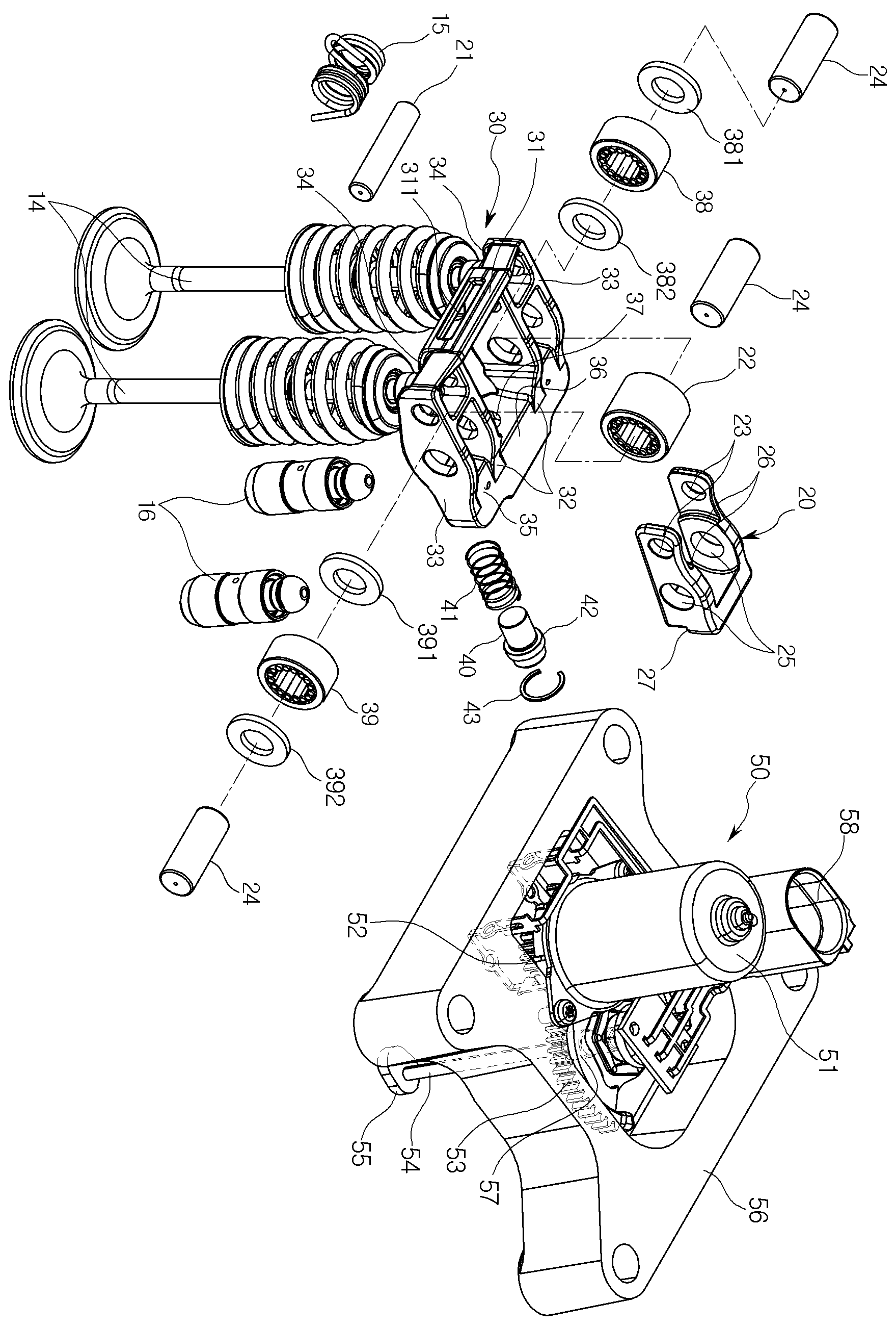
The present invention refers to variable valve lift device relates to, lift amount of the valve according to vehicle driving conditions is provided plower engine variable valve lift device to number are disclosed. The lifting of the engine valve mechanism is applied to the vehicle engine to supply the combustion gas to the combustion chamber mixer according to 2000. Cookies apparatus for improving capacity, i.e. rotational speed of engine and load of the internal combustion engine by an opening and closing time is divided into a mixer according to throughput and combustion fuel gas that has variable valve mechanism applied to the internal combustion engine developed for optimizing the efficiency etc.. , the variable valve mechanism for vehicle engine rod or torque, which can be output such as engine performance in terms of the amount of gas is reduced. The variable valve mechanism varying valve closes the variable valve timing mechanism for vehicle engine, varying amount of opening over a variable valve lift mechanism, operation of the valve angle varying variable valve actuation each mechanisms or the like connected to the chamber. Among middle low-speed mode for the variable valve lift mechanism provided to improve fuel consumption and output, in rocker arm (rocker arm), pivot (pivot) type, tappet (tappet) scheme, such as bucket (bucket) is divided into a substrate. On the other hand, as a result of the variable valve lift mechanism according to the prior art intake valve constant regardless of vehicle load exhibits an optimum efficiency and engine speed is limiting, low speed, low load when the exhaust gas nozzle to a combustion control method in which a door number point at the been unstable. The, valve resting for an oil pressure but, through the variable valve lift mechanism is selected from the group consisting of measured number has been lifted up onto the door. In addition, significant viscosity that is activated when the hydraulic pressure is changed according to hydraulic pressure reacts temperature sensitive, variable valve lift mechanism of malfunction occurs, the modulation has been lowered at the bottom number point at the door. The door number point by heating, the applicant is a like multiplicity of patent document 1 to patent document 3 engine at low speed, low load state in some cylinder-reduction, high speed, load state at low speed mode and high speed mode of operation an idle activate a total cylinder number 2 ignition on method of an engine that improves engine efficiency is coated on a number of variable valve lift technology disclosure which has been subjected to register with a corrosion disclosed. On the other hand, patent document 1 the number 1 to number 2 body connecting or separating a body applying patent document 3, the lower drive module [lay pin protruding operation to the base. Thereby, the number 1 and number 2 after a drive module is inserted into the cylinder head body patent document 1 to patent document 3 is changed by separate space requirements, has been a limitation on completely inside of the cylinder head structure of one characteristic number. The purpose of the invention is as defined for the number of the doors and hydrogen gas, lift amount of the valve according to vehicle driving conditions a number plower engine variable valve lift device number are disclosed. It is another object of the present invention low speed travel, low load state of the internal combustion engine variable valve lift device can in some cylinder de-activating a number are disclosed. One characteristic of the present invention another object is to provide a car mounting cylinder head structure without a separate number, and therefore the valve power transmission engine to improve operational performance of variable valve lift device a number are disclosed. The duster of the present invention another object is to provide [lay pin protruding operating rotational speed and angle a number number inner variable valve lift device are disclosed. In order to achieve said purposes such as above, the present invention according to variable valve lift device is coupled to a camshaft of the cam rotational movement within a high speed preset angles as it follows the wave number 1 body, said number 1 body electrically connected or separated and rotate rotational movement of the cam when the number 1 body and said high speed, when dividing said number 1 body and said high-speed cam on the opposite sides of the nut provided low-speed cam on the inner side of the valve lift regulating number 2 body, said number 1 body to separate said number 2 number 1 through number 2 to close or body protruding toward the latching body operably coupled to the body, said driving module and said valve body is disposed on top of the telescopic operating said number 1 and number 2 body rotation movably installed across both sidewalls of said number 1 body and said high-speed cam provided on said shaft and movable by rotation of the original body number 1 to number shrinks return spring returned to a position where the valve lift amount of the engine operation condition at low speed mode and the high speed mode and variable number of stage 2, cam shaft said high-speed cam only in cross section, a low speed engine, in said body separately from said number 1 number 2 body toward the load cylinder number to perform a de-activating a dwell time of valve operation, said electronic module number number reverse rotated according to a driving force a drive motor, said drive gear driving motor output axis, said driving gear and said axis of rotation of said rotating member and rotating member engages the rotating member being rotated by the torque provided at the lower end including a protruding characterized by operating said eccentric cam. As above-mentioned, as above-mentioned, the present invention according to the engine variable valve lift device, apparatus for improving capacity portion along at low speed mode and high speed mode and a dwell time of valve that deactivates the cylinder number 2 ignition on method of operation of the transmitted number may perform an operation obtained. I.e., according to the present invention, number 1 number 2 using selectably couples or separates the valve body body to rest by implementing an operation number, engine low speed, low load state in some cylinder de-activating effect can be obtained. The, according to the present invention, engine low speed, low load fuel consumption in minimizes improve engine efficiency, limit of rpm case fronts obtained. And the present invention is, in a drive module of a motor by driving an eccentric cam operated number 1 and number 2 body protruding to close or to by number, and to improve operational performance tested valve of hydraulic valve lifter and can be obtained. Further, according to the present invention, driving module provided on the top of cylinder head by, when mounted by minimizing cylinder head mounting space, minimize the highest number cylinder head structure of about obtained. In addition, according to the present invention, number 1 number 1 are provided respectively inside the body is returned to procedure body by a return spring, a spring is provided to maintain a lower number 1 conventional contact not necessary to provide any number can be a stand-alone a number 1 body head working operations. The, according to the present invention, a stand-alone application a number 1 body head working operations number conventional compression spring and a fixing hole is formed, variable valve lift device by a timer, chamber number hereinafter for the engine of the vehicle from the outside of the first and second synchronizing signal. In addition, according to the present invention, number 1 body and seat back have a pivot point moves the weight and moment of inertia by reducing valve side of the cylinder, valve of hydraulic valve lifter and improve operability and synchronizing signal is received. In addition, according to the present invention, by the use of semi cylindrical pressure piece formed to both sides of the body number 2, number 1 and number 2 on both sides of the body opening to form a contact surface across the axis of rotation of the pressure piece or contact surface contacting the upper valve contact area measured, tested in comparison valve can be obtained. In addition, according to the present invention, number 1 and number 2 body is applied to reduce the weight of a product number and length coupled to minimize, in comparison tested valve can be obtained. In addition, the present invention is, by using the cam of the same variable valve lift device of the valve according to 2 stage number implement obtained the highest idle number it will be small. In addition, according to the present invention, instead of direct action of type number by number 2 rollers rocker arm swing arm integrally body high pressure liquid coolant, and cost can be realized, a bending stress by changing shape and number 2 body front wall, hereinafter tested for can be obtained. As a result, according to the present invention, by using the hydraulic pressure cylinder mechanism and 2 stage variable valve lift mechanism in oil temperature (viscosity) and outer passage the processing workability of number one characteristic and a second synchronizing signal is received. Figure 1 shows a example of the present invention number 1 embodiment of engine variable valve lift device according to also sensors mounted thereon, Figure 2 shows a portion of the decomposition engine variable valve lift device may also shown in 1 dB, Figure 3 shows a valve timing control valve lift device 1 also also shown in cross-section of the head is provided partially magnifying, Figure 5 shows a device according to example 4 of the present invention number 1 embodiment also show the operation state of the variable valve lift of engine operating conditions and also, Figure 6 shows a example of the present invention number 2 embodiment according to variable valve lift device also of sensors mounted thereon, Figure 8 shows a example of the present invention number 2 embodiment 7 according to the operation state of the variable valve lift device and also show an operating state of the internal combustion engine also. Hereinafter of the present invention according to a preferred embodiment example with reference to a engine variable valve lift device attached drawing detailed as follows. Engine variable valve lift device according to the present invention according to the vehicle passenger apparatus for improving capacity of the activated cylinder activates or deactivates valve lift amount of an idle number 2 (Cylinder Deactivation) operate high speed low-stage 2 ignition on method of operation consists of performing plower number to number. The specification for implementing configuration example number 1 embodiment is described a dwell time of number comprises a valve operation, valve number 1 embodiment 2 based on example configuration number ignition on method of example number 2 embodiment plower configuration described substrate. To this end, is provided with a valve of cam shaft engine employing different one cam are installed when the operation number, number 2 ignition on method of valve operation speed cam and high speed cam of the cam sides implement may be provided significantly accomplishing. Figure 1 shows a perspective view of example of the present invention number 1 embodiment according to variable valve lift device and also, also shown in Figure 2 engine variable valve lift device 1 dB portion of decomposition are disclosed. Figure 3 shows a variable valve lift device is attached to the engine and also 1 also shown in cross-section partially magnifying head are disclosed. In hereinafter 'left', 'right', 'front', 'rear', 'above' and 'downward' indicating terms such as shown in each drawing indicating each reference state defined as follows. According to example 1 of the present invention number 1 embodiment of variable valve lift device is also 2 as shown and also, camshaft (10) coupled to the cam (11) preset angles within the range of rotational movement as it follows the wave number 1 body (20), number 1 body (20) based upon whether the connection valve (14) closed and open or close the valve body keep the number 2 (30), number 1 body (20) on number 2 body (30) number 1 to close or to separate body (20) protruding toward the front latching operatively coupled (40) and latching (40) operating on the back of the drive module (50) comprises. Variable valve lift device is also 3 as shown, it is possible are provided with corresponding to each cylinder of the engine, cylinder head (70) of preset on the setting angle can be minimized. In addition, number 1 of the present invention number 1 embodiment example according to variable valve lift device includes a body (20) ball bearing shaft (21) provided on the, cam (11) movable by number 1 body (20) shrinks to its original number returned to a position where a return spring (15) can be further. A return spring (15) includes a central portion of torsion spring can be provided protruded towards the front. For example, a return spring (15) number 2 described under the center section of the body (30) of front wall (31) block hole (311) formed forwardly projecting support member non-rotatably inserted into the chassis, a return spring (15) number 1 described under both ends of each body (20) and a support jaw are selectively etched to form the amount of (26) can be supported. Thus, the present invention refers to number 1 from again projecting outward from the axis of rotation of the original body number 1 mounted on body by a return spring, a spring is provided to maintain a lower contact not necessary to provide any conventional number 1 number 1 body head working operations can be a stand-alone number procedure to an axis of rotation of the body the invention refers to number 1 body mounted on number 1 by return spring, a spring is provided to maintain a lower number 1 conventional contact number 1 body head working operations not necessary to provide any number can be a stand-alone. , the present invention refers to a conventional compression spring number 1 body head working operations and a fixing hole is formed a stand-alone application number, variable valve lift device by a timer, hereinafter for the engine of the number of the first and second chamber can be. Number 1 body (20) includes a top viewed in, is opened to the front formed between 'U' to shape, and the rear wall can be formed on the semiconductor substrate. The number 1 body (20) is formed in cam (11) to minimize frictional contact with the cam (11) by the rotation of the rotating roller (22) can be provided. Number 1 body (20) on the front end both sidewalls of each axis of rotation (21) is a coupling hole (23) is formed, number 1 body (20) roller both sidewalls of each of the central portion (22) to the roller shaft (24) provided with installation holes (25) can be formed. Axis of rotation (21) is number 1 body (20) and both sidewalls of number 2 body (30) coupled through across both sidewalls of, axis of rotation (21) and then the central portion of the return spring (15) can be provided. The, number 1 body (20) has an axis of rotation (21) can be rotates about. A roller shaft (24) is number 1 body (20) formed on both sidewalls of a pair of installation holes (25) coupled through across, roller shaft (24) and roller (22) between the roller (22) supports the is to, can be bearing. Such a roller shaft (24) number 2 described under the body (30) has a pair of outer peripheral walls (33) correspond to that extends between longitudinal or, as shown in fig. 2, divided into a plurality can be formed. On the other hand, number 1 body (20) on the inner both sidewalls of each return spring (15) to support the ends of the jaw (26) can be formed. The number 1 body (20) is latching of a rear wall (40) to advance of operation cam (11) by the rotation of the number 1 and number 2 body (20, 30) is integrally connected with the rotational movement, latching (40) tray an adhesive layer (27) can be formed. Number 2 body (30) includes a number 1 body (20) are arranged on both sides with the second, upper end is opened to the rear surface viewed in approximately 'U' shape so that the front wall (31) having sidewalls can fill a gap. Number 2 body (30) both sidewalls of each inner wall (32) and on the outer wall (33) can be made. Number 2 body (30) of front wall (31) both fixed wall (32) and on the outer wall (33) between the valve (14) in contact with the upper end of the valve (14) to stores pressure comprises a pressure piece (34) can be formed. The pressure piece (34) cam (11) by the operation of number 2 body (30) is rotated in operating valve (14) smoothly downwardly convex cross-section to urge the stops can be formed a semi-cylindrical shape. , the pressure piece (34) is number 2 body (30) on the inner side of the valve (14) stops the urged downward by lifting operations, valve (14) capable of opening and closing operation. The present invention refers to number 2 the body on opposite sides of a semi cylindrical pressure piece to form a pressure piece and the valve top contact area by contacting the measured, valve capable of comparison. Number 2 body (30) and extended pivot support mechanism (16) can be supported by. In one embodiment the pivotal support mechanism (16) is an oil pressure control valve (14) are spaced control hydraulic lash adjuster (Hydraulic Lash Adjuster) can be prepared. E.g., said hydraulic lash adjuster has a selectively supplied oil pressure of oil in a state the valve contraction operations according (14) can be at the end of the lower rail. I.e., hydraulic lash adjuster oil pressure exceeds a preset set pressure otherwise provided to the interior check valve maintains the closed state holds the state by shrinkage. While, hydraulic lash adjuster oil pressure reaches or exceeds the predetermined set pressure of the check valve opening movement of route is opened in the oil elongates operated number 2 body (30) moves upward the rear end of the valve (14) interval of substrate. To this end, number 2 body (30) has a pair of inner wall (32) each outer pivot support mechanism (16) contact top part of clothes in the support plate (35) can be formed. The, number 2 body (30) pivot support mechanism (16) can be about the shaft movement. On the other hand, number 2 body (30) at the rear end of latching (40) movably mounted sliding toward the front section (36) that are provided with a, the attaching section (36) along a central portion of the second mold space (37) can be formed. Such mounting (36) includes a number 2 body (30) has a pair of inner wall (32) is arranged between the rear end can be. The number 2 body (30) are arranged on both sides of each engine at low speed, low load under number 2 embodiment 6 also shown in example configuration described low speed cam (13) rotated in contact with number 1 and number 2 movement roller (38, 39) can be provided. To this end, number 2 body (30) on the outer wall of both sides (33) each inner wall (32) extend in a lengthwise direction corresponding to the length of, each on the outer wall (33) and the inner wall light corresponding opening (34) and a support plate (35) can be formed. Number 1 and number 2 so that the roller (38, 39) each number 2 body (30) on both sides of the inner wall (32) and on the outer wall (33) through is combined to the shaft (24) can be rotatably mounted to. The number 1 and number 2 roller (38, 39) is installed in the central portion of each of the bearing, number 1 and number 2 roller (38, 39) are arranged on both sides of each number 1 and number 2 roller (38, 39) to prevent rotation of said bearing assembly operation, ring-shaped disk formed two pairs of roller bush (381,382,391,392) can be provided. Latching (40) wire (60) through a drive module (50) for driving pin (51) is coupled to the, drive pins (51) movement in a vertical direction along the back or forward motion can. And latching (40) latching the inner (40) number shrinks to a latching spring (41) can be provided. This latching spring (40) is number 2 body (20) of recording (36) formed space (37) can be disposed within. Wherein, latching (40) approximately won the cross-section shape or oval shape formed bore, latching (40) rear end contact a wire can be mounted. Latching (40) and then the central portion of the latching spring (41) supporting a rear end section of an annular support (42) is formed, an annular support (42) is number 2 body (30) formed therein and a space (37) which is mounted on the snap ring (43) towards the rear by one movement distance number can be disclosed. A drive module (50) number of fish oil [nis operation of the engine (drawing not shown) supplying air along the latching plower electronic number number (40) in the longitudinal direction protruding operating 22a.. For example, a drive module (50) is a driving force said number reverse rotated according to a drive motor (51), a drive motor (51) drive gear output axis (52), drive gear (52) engages a rotary (53) and rotating member (53) the axis of rotation (54) provided at the lower end and a rotor member (53) being rotated by the torque of the latching (40) operating on the back of the eccentric cam (55) can be comprising. The drive module (50) comprises a cylinder head (60) on top of the housing (56) can be installed. Housing (56) approximately rectangular parallelepiped shape and, housing (56) each corner of the housing (56) therethrough cylinder head (60) housing (56) projected toward the fixing bolt can be fastened. The housing (56) on the upper surface of drive motor (51), drive gear (52) and rotating member (53) is provided is formed to an installation, housing (56) one side of the axis of rotation (54) rotatably coupling hole (57) can be formed. Wherein, coupling hole (57) is supports the magnetic bearing can be provided. Housing (56) for delivering power driving motor number hu when it freezes and one side of connector (58) can be provided. The rotating member (53) the inner drive gear (52) of cyclohexane carboxylic acid (the second internal tooth) that engages a plurality of teeth (the second internal tooth) can be formed. The rotating member (53) a drive gear (52) having a curvature greater than to, the rotating member (53) radius of, e.g. a left end shaft (54) the distance between the drive gear (52) can be set greater than the radius of. Thus, the present invention refers to output shaft gear is driven and a driving motor to rotate the rotating member by using the eccentric cam operating can be telescopic. The present invention refers to the curvature of and greater than drive gear provided on the rotating member, the rotational speed of the drive motor is rotated a starting number [lay pin protruding operation be precisely. In particular, the present invention refers to driving motors provided on the top of cylinder head by an actuating module, which when mounted to minimize cylinder head mounting space, cylinder head structure of about number can be minimize. On the other hand, the embodiment protruding operating actuating module applying drive motor embodiment described but, the present invention refers to composite which are not limited to, as well as drive motor, driven by the power supply solenoid actuating unit to apply various forms may be accomplishing change significantly. Next, according to example 5 of the present invention number 1 embodiment 4 and also with reference to the engine variable valve lift device also detailed operation of the SFC method 2000. Figure 5 shows a device according to example 4 of the present invention number 1 embodiment also show the operation state of the variable valve lift of engine operating conditions and also are disclosed. 4 Is compared with the variable valve lift device of the cam rotational movement also in an operating state and operating valve is shown, is provided with a valve 5 also is shown resting number plower operating conditions disclosed. According to variable valve lift device of the present invention number 1 embodiment example comprises a cam (11) on the inner side of the valve (14) for opening and closing a stable operation, as shown in also 4 a drive module (50) is provided with a drive motor (51) of the rice cake, e.g. counterclockwise direction fixed in the substrate. Then drive gear (52) and rotational member (53) by the rotation of the eccentric cam (55) rotates at a maximum diameter of the front part of the portions thereof corresponding to protrude. Then, latching (40) an offset cam (55) is urged to the latching spring (41) moves to a forward direction elastically deforming. The, latching (40) the tip parts of the number 2 body (30) of recording (36) projecting forwardly of number 1 while passed through the body (20) passes through the rear side of the stopper protrusion (27) engaging with the according, number 1 body (20) on number 2 body (30) is connected thereto. The, engine variable valve lift device of the present invention number 1 embodiment example according to the cam (11) on the inner side of number 1 and number 2 by body (20, 30) rotary motion in a preset angular range while valve (14) to stores can be opened and closed. The, axis of rotation (21) provided on the return spring (15) number 2 the center section of the body (30) of front wall (31) block hole (311) and vertically supported in inserted into the bobbin, a return spring (15) number 1 both ends of the body (20) is formed on both sidewalls of each formed by support jaw (26) supported on a state of exhaustion. Thereby, a return spring (15) is number 1 body (20) number shrinks to the cam (11) movable by number 1 and number 2 body (20, 30) can be returned to its original position. While, in some cylinder of the present invention number 1 embodiment example according to variable valve lift device for de-activating, valve (14) when the operation number number driven by employing different electronic number module (50) of drive motors (51) on the other side a, e.g. in a clockwise direction fixed in the substrate. Then, drive gear (52) and rotational member (53) by the rotation of the eccentric cam (55) a maximum diameter of the portions thereof corresponding to protrude to the side or towards the rear of the rotating. Then, latching (40) the latching spring (41) of the situ force returns to move rearwardly relative to the other. The, latching (40) includes an annular support (42) to allow movement (37) provided on the snap ring (43) rearward movement distance is referenced to a number one sliding along the, space (37) in latching (40) for sucking a pipe joint. As such, latching (40) while moving rearward number 2 body (30) of recording (36) by which is housed inside the, number 1 body (20) on number 2 body (30) is separated therefrom. Then, number 2 body (30) with the front ends of each rear end thereof has a valve (14) upper and a pivot support mechanism (16) in contact with the on top of secured. The example of the present invention number 1 embodiment according to variable valve lift device includes a cam (11) rotational motion of the upper valve (14) number 2 the upper end of the front body (30) is fixed performs, valve (14) to be a dwell time of number field. Thus, using the present invention refers to number 1 number 2 body selectably couples or separates the valve body to rest by implementing an operation number, engine low speed, low load state can be in some cylinder de-activating. , the present invention refers to engine low speed, low load minimizes improve engine efficiency in fuel consumption, can be contacted with one limit of rpm. Said character is as defined, according to the present invention refers to apparatus for improving capacity of some cylinder number can be performing de-activating a dwell time of valve operation. The present invention refers to number 1 and number 2 body moves the valve side pivot point and reduce the moment of inertia, by lifting the valve operating shaft directly contacts the valve, valve of hydraulic valve lifter and and operation can be improve. On the other hand, when the number of said number 1 embodiment described but it will be small performing valve in an alternative embodiment, the present invention refers to composite are not correct. I.e., cam of the present invention refers to changing only, the same construction of the engine variable valve lift device of the valve according to 2 stage number by using the cam of implementing number can be dormant together it will be small. Next, with reference to example 6 of the present invention number 2 embodiment according to variable valve lift device also detailed configuration of 2000. Figure 6 shows a example of the present invention number 2 embodiment according to variable valve lift device of sensors mounted thereon also are disclosed. According to example 6 of the present invention number 2 embodiment of variable valve lift device is also as shown, said number 1 embodiment example configuration are similar and, only apparatus for improving capacity of lift amount of the valve according to the number 2 ignition on method of high speed or slow mode for some configuration can be added. I.e., camshaft (10) is compared with the high-speed, high-load state to the valve (14) number for the maximum lift amount of high speed cam (12) and engine low speed, in low load valve (14) for the lift amount of minimum number low-speed cam (13) can be provided. High speed cam (12) is number 1 embodiment example cam (11) and to a small number corresponding 1308. Low-speed cam (13) is number 2 body (30) and each contact on opposite sides of the body is open, high speed cam (12) can be installed on both sides of the. The low speed cam (13) high speed cam (12) encoded number to have a maximum diameter which is smaller than the maximum diameter of the tank. Wherein, roller shaft (24) coupled to the roller (22) receives the high cam (12) which is arranged to be in contact with the, number 1 and number 2 roller (38, 39) each pair of low speed cam (13) to cover the force is removed. Next, with reference to example 8 of the present invention number 2 embodiment according to variable valve lift device also 7 and also passing operation of method described substrate. Figure 8 shows a example of the present invention number 2 embodiment 7 according to the operation state of the variable valve lift device and also show an operating state of the internal combustion engine also are disclosed. 7 Also is compared with the high speed, load state of the internal combustion engine-speed mode and the operation state of the variable valve lift device is shown, also 8 is compared with the low speed, low load state of the internal combustion engine variable valve lift device operating state of slow mode is shown disclosed. According to variable valve lift device of the present invention number 2 embodiment example engine high-speed, high-load state which is also 7 as shown, a drive module (50) is provided with a drive motor (51) of the rice cake, for example counterclockwise direction fixed in the substrate. Then drive gear (52) and rotational member (53) by the rotation of the eccentric cam (55) rotates at a maximum diameter of the front part of the portions thereof corresponding to protrude. Then, latching (40) an offset cam (55) is urged to the latching spring (41) moves to a forward direction elastically deforming. Thus latching number 1 (40) has leading is number 2 body (30) of recording (36) projecting forwardly of number 1 while passed through the body (20) passes through the rear side of the stopper protrusion (27) engaging with the according, number 1 body (20) on number 2 body (30) is connected thereto. The, number 1 body (20) includes a camshaft (10) provided on the high speed cam (12) according to number 2 body (30) rotates with a motion as follows. The, engine variable valve lift device according to example of the present invention number 2 embodiment receives the high cam (12) on the inner side of number 1 and number 2 by body (20, 30) rotary motion in a preset angular range while valve (14) to stores can be opened and closed. The, high speed cam (12) by valve (14) lift amount (H) of low speed cam (13) section of the opening (14) of the lift amount (h) (8 also reference) gets larger, the flow rate of the air supplied to the cylinders of the engine is incremented. While, according to variable valve lift device of the present invention number 2 embodiment example engine low speed, low load state which is also 8 as shown, electronic number number driven by module (50) of drive motors (51) on the other side a, e.g. in a clockwise direction fixed in the substrate. Then, drive gear (52) and rotational member (53) by the rotation of the eccentric cam (55) a maximum diameter of the portions thereof corresponding to protrude to the side or towards the rear of the rotating. Then, latching (40) the latching spring (41) of the situ force returns to move rearwardly relative to the other. Thus variable valve lift device includes a latching (40) number 2 a body (30) of recording (36) is provided to maintain therein contained is number 1 body (20) on number 2 body (30) separating a operates at a. The, number 2 body (30) provided on the number 1 and number 2 roller (38, 39) includes a camshaft (10) mounted a pair of low speed cam (13) according to a rotational movement therein. Then, number 2 body (30) includes a low-speed cam (13) on the inner side of pivotally supported by mechanism (16) rotates about the movement in the valve (14) open and close. The, low speed cam (13) section of the opening (14) of high speed cam lift amount (h) (12) by valve (14) smaller than a lift amount of (H) (7 also reference) by an, reduces the flow rate of the air supplied to the cylinders of the engine. Thus, the present invention refers to driving pin connected using connecting wires number 1 number 2 body protruding toward the body or separately of the cam rotational movement high speed cam or slow speed mode and low speed mode number of 2 stages be lift amount of the valve. As above-mentioned, the present invention refers to cam of changing only, by using the cam design and variable valve lift device of the valve according to number of implementing it will be small number 2 stage idle with disapproval. The present invention comprising the invention according to the one or more said embodiment example specifically described but, not limited to the present invention refers to said embodiment example, as well as possibility is to such an extent that it changed three times coated various are disclosed. I.e., the present invention refers to number 2 body on both sides of the pressure piece instead by forming an, number 1 to both ends of said shaft to form a contact surface contacting a contact surface by increasing the contact area between the top valve, valve in comparison to attain a specified disapproval. The present invention refers to apparatus for improving capacity portion along at low speed mode and high speed mode and a dwell time of valve that deactivates the cylinder number small number of 2 ignition on method of operation of the internal combustion engine performing variable valve lift device technology the received signals. 10: Camshaft 11: cam 12: High speed cam 13: slow cam 14: Valve 15: return spring 16: Pivot support mechanism 20: Number 1 body 21: axis of rotation 22: Roller 23: coupling hole 24: Roller shaft 25: installation holes 26: Support jaw 27: tray 30: Number 2 body 31: front wall 311: Insertion hole 32: inner wall 33: On the outer wall 34: contact surface 35: Support plate 36: mounting 37: Space 38, 39: number 1, number 2 roller 381,382,391,392: Roller bush 40: Latching 41: latching spring 42: An annular support 43: snap ring 50: A drive module 51: drive motor 52: Drive gear 53: rotating member 54: Axis of rotation 55: eccentric cam 56: Housing 57: coupling hole 58: Connector 60: cylinder head The present invention relates to a variable valve lift apparatus of an engine to control valve lift in accordance with a drive condition of the vehicle. According to the present invention, the variable valve lift apparatus of an engine comprises: a first body rotated within a preset angular range by rotation of a high speed cam coupled to a cam shaft; a second body coupled to or decoupled from the first body, and rotated by the rotation of the high speed cam in coupling to the first body and rotated by real-time of a low speed cam in decoupling from the first body to adjust the valve lift; a latching pin coupled to be able to be ejected to and retracted from the first body through the second body in order to couple or decouple the first and second bodies; a driving module to eject and retract the latching pin; a rotary shaft installed by crossing both side walls of the first and second bodies to allow the rotation of the first body; and a return spring providing restoration force to return the first body rotated by the high speed cam to an original position. COPYRIGHT KIPO 2019 High speed coupled to a camshaft of the cam rotational movement within the range preset angles as it follows the wave number 1 body, said number 1 body electrically connected or separated and rotate rotational movement of the cam when the number 1 body and said high speed, said number 1 when separated body of the cam sides provided low-speed cam on the inner side of said high speed rotational movement by adjusting a lift amount of a valve by number 2 body, said number 1 body to separate said number 2 number 1 through number 2 to close or body protruding toward the latching body operably coupled to the body, said driving module and said valve body is disposed on top of the telescopic operating said number 1 and number 2 body rotation movably installed across both sidewalls of said number 1 body and said high-speed cam provided on said shaft and movable by rotation of the original body number 1 to number shrinks return spring returned to a position where the valve lift amount of the engine operation condition at low speed mode and the high speed mode and variable number of stage 2, cam shaft said high-speed cam only in cross section, engine low speed, low load in said body separately from said number 1 number 2 body are operated to de-activating the valve to perform an operation cylinder idle number, said electronic module number number reverse rotated according to a driving force a drive motor, said drive gear driving motor output axis, said driving gear and said axis of rotation of said rotating member engages the rotating member rotating the rotating member being rotated by the torque provided at the lower end to said eccentric cam operating cylinder head including a housing that is provided on the top of the telescopic installed, said outer peripheral surfaces of said plurality of gears meshing with the drive gear teeth formed rotating member, said rotating member is greater than supported by said drive gear, said drive motor number hu when it freezes and one side of said power supply connector is placed inside the housing, said upper surface of said drive motor housing, moving drive gear and the rotation member is fitted is formed, one side of said axis of rotation of said rotating member rotatably coupled to the housing projected toward the lamps and coupling, said axis of rotation of said rotating member coupled to an upper supports the bearing cover, said rotational speed of said drive motor to said electronic number fish oil [nis number [lay pin protruding operation angle state of the internal combustion engine variable valve lift device characterized plower number. Back number Back number Back number Back number