METHOD AND APPARATUS FOR LTE-WLAN AGGREGATION INTERWORKING PROTOCOL
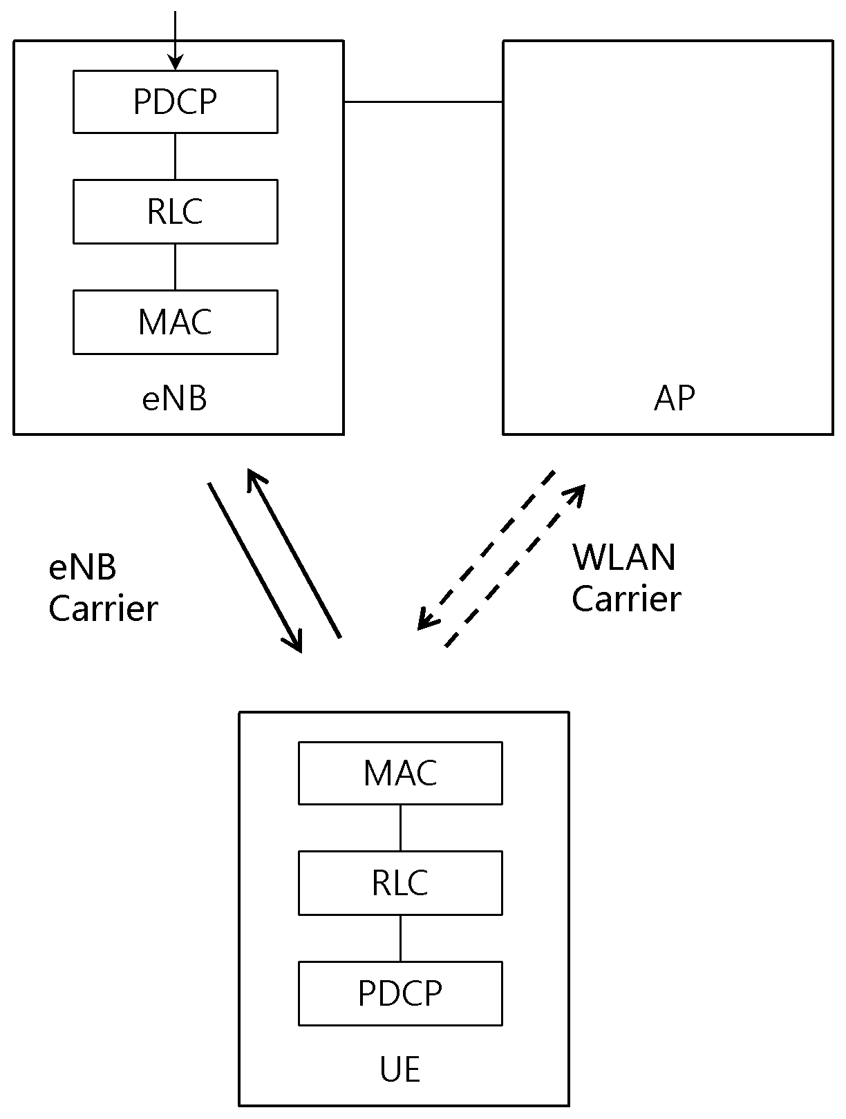
In the present invention refers to RAN (Radio Access Network) level for WLAN E-UTRAN carrier in addition to user plane or not the transfer of data in, between a base station and a terminal identifies a user plane data WLAN through for transmitting and/or receiving relates to device and method. User plane terminal is the present invention refers to method for transmitting data in, a WLAN E-UTRAN a step of adding a carrier to a position in; and individual electronic package PDCP on user plane data unit separation or by linking E-UTRAN carriers and/or WLAN carrier for transmitting data user plane required separation or interlock provides device and including method step. Uplink/downlink data transmission path also Figure 1 shows a one example of it is shown a. plane from the. Uplink/downlink also Figure 2 shows a in another example of a data transmission path it is shown a. plane from the. Figure 3 shows a also uplink/downlink data transmission path is another example of an it is shown a. plane from the. Figure 4 shows a also uplink/downlink data transmission path is another example of an it is shown a. plane from the. Figure 5 shows a user plane protocol structure also the present invention according to one example of it is shown a. plane from the. Figure 6 shows a user plane protocol structure also the present invention according to one example of it is shown a. plane from the. Also the present invention according to Figure 7 shows a user plane protocol structure in another example of a it is shown a. plane from the. Another also Figure 8 shows a configuration of base station based on a received embodiment show. surface thereof, and the. Also Figure 9 shows a another embodiment of a user terminal based on a show configuration. surface thereof, and the. Hereinafter, part of the present invention in the embodiment are an exemplary drawing. rapidly and to reduce a memory through. Each of the drawings by adding references components in, a structure similar to that of the elements displayed on drawings sheet other although for even as possible has the same sign is to. to significantly different. Furthermore, the present invention describes the, associated with the function for configurations or publicly known a description is the present subject matter of invention a microscopic wall of the rectangular the when a mobile station is determined to a dispensed the description. The present specification in low cost terminal MTC (or low complexity) coverage enhancement terminal or for supporting for supporting terminal can be means. The present specification (or low complexity) and low cost terminal MTC in coverage enhancement for supporting terminal can be means. MTC in specification or low cost terminal (or low complexity) for supporting and/or coverage enhancement defined by a particular category can be means terminal. In other words, the present specification in LTE terminal MTC MTC-related operation performing based on defined new UE category/type 3GPP Release-13 low cost (or low complexity) can be means. In the existing terminal MTC specification or a CPT supporting LTE coverage or coverage, low power consumption or existing and supporting UE category/type 3GPP Release-12 hereinafter defined in, or defined new UE category/type Release-13 low cost (or low complexity) can be means. A voice radio communication system in the present invention, packet data device includes an organic membrane comprising such providing a group communication service such as are arranged to save a manufacturing cost. Wireless communication system at the user terminal (User Equipment, UE) and base station (Base Station, BS, or eNB) includes. The present specification in wireless communications user terminal in means terminal in a generic, as general outline, LTE and WCDMA, HSPA UE (User Equipment) in well as, MS (Mobile Station) in GSM, UT (User Terminal), SS (Subscriber Station), including general outline both wireless device (wireless device) or the like will should be the layout based upon the resistance value. Base station or cell (cell) is generally in communication with user terminal (station) and a surface of the point, node-B (Node-B), eNB (evolved Node-B), sector (Sector), (Site) site, BTS (Base Transceiver System), access point (Access Point), relay node (Relay Node), RRH (Remote Radio Head), RU (Radio Unit), as small cell. can be referred to as terms. I.e., the present specification (cell) cell from the BSC (Base Station Controller) in CDMA, WCDMA of NodeB, such as in LTE eNB or sector (site) appear to function region or portion is the cover in a generic, must be interpreted to into the, mega cells, Macrocell, microcell, picocell, femtocell and relay node (relay node), RRH, RU, small cell communication range of a polyimide resin, such a coverage area is, and a semantic comprehensive both. Each cell said additionally prepared various cells formed through the base station controlling the widest sense of two base station may be interpreted.. I) wireless area in connection with mega cells, Macrocell, microcell, picocell, femto-cell, small for providing device itself or, ii) said wireless area itself can indicate. I) predetermined wireless area for providing the same device by the originating entity controlled or said wireless area for collaborative composed all interact with one another to cause the device indicates the base station as a function of. ENB according to configuration of wireless area, RRH, antenna, RU, LPN, point, transmitting/receiving point, transmission point, receiving point is substracte embodiment of a base station. Ii) of a user terminal in aspect with the latitude and the longitude of a neighboring base station or, to receive and transmit signals in a wireless area serves as a static representation of the base station can be sides and pointing downwards in the roll. Therefore, mega cells, Macrocell, microcell, picocell, femto-cell, small cell, RRH, antenna, RU, LPN (Low Power Node), point, eNB, transmitting/receiving point, transmission point, receiving point referred to as the a the base station them. The present specification files from user terminal in and a base station described in the present specification for technical idea or techniques used to implement mainly consisting of two transmitting/receiving the comprehensive, which are referred to specifically in which a high term or word is not limited by. The and a base station user terminal, which is described in the present invention used to implement a technical idea technique or two (Downlink or Uplink) mainly consisting of transmitting/receiving the comprehensive, which are referred to specifically in which a high term or word is not limited by. Wherein, uplink (Uplink, UL, or uplink) user terminal to the base station by the for transmitting and receiving data how initiator, downlink (Downlink, DL, or downlink) the base station to the user terminal by the. how for transmitting and receiving data. Wireless communication system applied to multiple access technique will't. CDMA (Code Division Multiple Access), TDMA (Time Division Multiple Access), FDMA (Frequency Division Multiple Access), OFDMA (Orthogonal Frequency Division Multiple Access), OFDM-FDMA, OFDM-TDMA, various features such as OFDM-CDMA multi-access technique, use can be made of,. GSM one embodiment of the present invention relate, WCDMA, HSPA LTE-advanced and LTE via a and asynchronous wireless communication extinguishing to, CDMA, to extinguishing UMB and CDMA-2000 for synchronizing type wireless telecommunications applications such as can be applied on the resource allocation. The present invention refers to a particular wireless communication field is the interpretable confined or limited is not, event has of the present invention which can be applied including all addresses the technical field will should be interpreted to. Uplink transmission different downlink transmission and sent using time TDD (Time Division Duplex) can be scheme is used, or different frequency transmitted using a FDD (Frequency Division Duplex) can be scheme is used. Furthermore, LTE, LTE-A such as system one carrier or carriers based on the pair constituting a to enable an uplink and a downlink to specifications is constituted with a. A to enable an uplink and a downlink, PDCCH (Physical Downlink Control CHannel), PCFICH (Physical Control Format Indicator CHannel), PHICH (Physical Hybrid ARQ Indicator CHannel), PUCCH (Physical Uplink Control CHannel), such as EPDCCH (Enhanced Physical Downlink Control CHannel) over a control channel and sending control information on a, PDSCH (Physical Downlink Shared CHannel), PUSCH (Physical Uplink Shared CHannel), and channels that and transmits the data. While (extended PDCCH or enhanced PDCCH) EPDCCH tone can be for transmitting control information. The present specification (cell) conver-sion from a point transmission and reception in which cell coverage of the signals to be transmitted (transmission point or transmission/reception point) from or transmit/receive point of the signals to be transmitted (component carrier) carrier element having coverage, self point thereof transmitting and receiving can be mixture by the addition of an initiator. In the embodiment applied for transmitting and receiving two or more wireless communication system wherein for transmitting signals cooperate points a multiple point cooperated transmission/reception system (coordinated multi-point transmission/reception System; CoMP system) or cooperated multi-antenna transmission manner (coordinated multi-antenna transmission system), cooperated multi-cell communication systems may be a system.. CoMP system comprises at least two multiple transmitting/receiving point and may include a terminals. Multiple transmitting/receiving point a base station or macro cell (macro cell, assembling and welding steps' eNB ' hereinafter) and, are connected in or a fibre optical cable to eNB wired controlled, or Macrocell the highest transmit power in the region of at least one low transmission power may RRH. Hereinafter in downlink (downlink) has transmit at those points in communication or communication path to the mixture by the addition of an initiator, a terminal (uplink) uplink multiple transmit and receive in. communication path or communication to the point. Downlink in the transmitter and may be part of multiple transmit and receive point, may be part of terminal receiver. On the uplink comprises a and may be part of terminal transmitter, receiver may be part of multiple transmit and receive point. PUCCH in hereinafter, PUSCH, PDCCH, PDSCH and EPDCCH such as through a channel, such as a situation of PNP/NPN compound signal is' PUCCH, PUSCH, PDCCH, PDSCH EPDCCH and for transmitting, : this recorder receives' a also the form-time. In sending or receiving PDCCH in addition hereinafter or PDCCH signal to that through sending or receiving or sending or receiving EPDCCH substrate through EPDCCH to sending or receiving signal to the widest sense of including can be used. I.e., described hereinafter a physical downlink link control channel PDCCH or mixture by the addition of an initiator, EPDCCH can be mixture by the addition of an initiator, including both PDCCH EPDCCH and. used as meaning. Furthermore, for facilitating of the PDCCH or at a one embodiment of the present invention the part is formed at the hole which EPDCCH towed, the EPDCCH or at a one embodiment of the present invention enable the application EPDCCH to exemplify. On the other hand, an upper layer described hereinafter the RRC signaling (High Layer Signaling) for transmitting information including RRC parameters containing the signaling the RRC. The eNB performs downlink transmission terminals in the. The unicast transmission (unicast transmission) eNB a main for downward link sharing channel physical physical channel (Physical Downlink Shared Channel, PDSCH), and required for receiving the packet a PDSCH such as scheduling downlink control information and uplink data channel (for example physical uplink shared channel (Physical Uplink Shared Channel, PUSCH)) scheduling for transmission in a, approval information for transmitting physical downlink control channel (Physical Downlink Control Channel, PDCCH) able to transmit them. In hereinafter, through each channel signal is transmitted and received to corresponding channel is of PNP/NPN compound form is described as to the. Guide the standardization until December 2014 the 3GPP Rel-12 running on the, comprises a work items 3GPP/WLAN interworking. The aforementioned 3GPP/WLAN interworking provides inter-working function RAN assisted WLAN item. The E-UTRAN RRC_IDLE and the terminals and state RRC_CONNECTED WLAN traffic steering-based bidirectional terminal between E-UTRAN and can help a. E-UTRAN the terminal to broadcast and dedicated RRC provides parameter help via signaling. The parameters aid RAN E-UTRAN signal intensity because threshold, WLAN channel utilization threshold, threshold data rate backhaul WLAN, WLAN signal strength and Offload Preference Indicator may comprise an. In addition the E-UTRAN the via signaling broadcast terminal may provide a a list of WLAN identifiers. Terminal aid RAN in assessment of access network selection and traffic steering rules use an parameters. Access network selection and traffic steering rules (fulfilled) is satisfied when terminal (indicate) the indication lamp to the upper hierarchy AS (access stratum). When apply access network selection and traffic steering rules terminal, terminal APN granularity between E-UTRAN and performs traffic steering to WLAN. As said inter-working function Rel-12 RAN assisted WLAN (standalone) WLAN E-UTRAN and independently constructed by interlocked a method provides only. Folded finishing step work 3GPP Rel-12 the aforementioned while are compared to interworking Rel-12 RAN assisted WLAN RAN tight, in level which takes into account the integrated to increase need di star LTE WLAN aggregation of wet liquid to flow down. The interworking Rel-12 RAN assisted WLAN establishing an optical fiber at a side independently WLAN and E-UTRAN APN unit to operate at to use at only continued. Thus terminal a specific user plane or not the transfer of data out the overall control of the as a mask and a migrating wireless status RAN is E-UTRAN WLAN in level (carrier/wireless link/wireless/radio resource/wireless network) of the added one carrier in E-UTRAN E-UTRAN carrier WLAN carrier (or radio link/wireless/radio resource/wireless network) could not be applied to simultaneously. WLAN in level RAN is E-UTRAN (carrier/wireless link/wireless/radio resource/wireless network) of the added one carrier in E-UTRAN E-UTRAN carrier WLAN carrier (or radio link/wireless/radio resource/wireless network) for transmitting data user plane through order 2 layer E-UTRAN on user plane data unit separating (or split or routing) or interlock can be is taken into account in a method. For example in an individual PDCP E-UTRAN carrier data to send via WLAN and/or dividing groups are transmitted through carrier transmits the selected Huffman a PDCP S3a which receives it and in an individual (or merging received) may will not be used to. PDCP or WLAN in an individual carrier data to send via a PDCP transmits the selected Huffman linking in an individual which receives it and S3a to the first rear plate. Other for example, in an individual RLC E-UTRAN carrier data to send via WLAN and/or dividing groups are transmitted through carrier transmits the selected Huffman a S3a which receives it and in an individual RLC (or merging received) may will not be used to. RLC or in an individual carrier data to send via WLAN transmits the selected Huffman linking a S3a which receives it and in an individual RLC to the first rear plate However in the prior art based on interface with layer RLC layer PDCP which is standard, based on interface with layer MAC RLC layer constitution: of such a size that a. Thus PDCP layer or an RLC layer and data to send via carrier E-UTRAN WLAN carrier by linking separation or data to transmit transmission over a carrier WLAN PDCP layer or an RLC loaded in a cleaning apparatus is requested from lower hierarchy layer cannot be application provides for a communication presentation or the PDCP layer or an RLC layer of action with the content is to may not inoperable. RLC layer PDCP for example with hierarchy and the lower hierarchy so as through an interface standardized functions of PDCP layer by using the mask pattern.. RLC layer for example an indication as to successful transfers receives the confirmation including handover in a must to be run without error in on an idle gear shaft. As described above the terminal E-UTRAN conventional particular user plane or not the transfer of data in a WLAN and added one carrier in E-UTRAN E-UTRAN layer 2 on user plane data unit separation or by linking WLAN E-UTRAN carrier for transmitting data user plane carrier could not be applied to. E-UTRAN layer 2 during each sub-layer PDCP layer on RLC hierarchy and the lower hierarchy so as through an interface standardized with PDCP layer function can provide therefore the, WLAN data user plane carrier is capable of delivering a hierarchically PDCP even existing operation in that they may or may not be inoperable. problem. Said returned reflectively difficulties the present invention refers to a specific user terminal or not the transfer of data plane in a WLAN E-UTRAN PDCP and added one carrier in individual electronic package on user plane data unit separation or by linking E-UTRAN carriers and/or WLAN carrier for transmitting data user plane required separation method or interlock in provides. The present invention refers to base station in scenarios where is non-co-located is WLAN AP and (eNodB) may be provided. Base station (eNodB) and is non-co-located is WLAN AP base station and in scenarios where the WLAN AP backhaul non-ideal (non-ideal backhaul) or near-ideal backhaul or ideal constructing/by bag can be. The present invention refers to base station scenario is co-located is WLAN AP and (eNodB) may be provided even. WLAN terminals in level RAN is E-UTRAN carrier/wireless link/wireless/radio resource/wireless network and added one carrier in E-UTRAN E-UTRAN carrier carrier/WLAN wireless link/wireless/radio resource/wireless network the user through the use of a plane and transmit and/or receive in order for the same protocol structure should of operation are provided each layer. WLAN or WLAN is E-UTRAN carrier/wireless link/wireless/radio resource/wireless network one carrier to logically adding general outline or recording medium, and records and a base station-frames are further cell E-UTRAN carrier/WLAN radio resource/wireless/wireless link (or L1/L2) WLAN PHY/MAC // wireless network for transmission provided to add a new function, to the wheelchair by blades, presenting a. WLAN terminals in level RAN is E-UTRAN (carrier/wireless link/wireless/radio resource/wireless network) of the added one carrier in E-UTRAN E-UTRAN carriers and/or WLAN carrier (or radio link/wireless/radio resource/wireless network) wireless bearer unit user plane to transfer the data of sub-layer 2 layer E-UTRAN on user plane data unit (or split or routing) separating the user or interlock can be to transmit data. For example in individual (or individual RLC) PDCP E-UTRAN carrier data to send via WLAN and/or dividing groups are transmitted through carrier transmits the selected Huffman S3a a PDCP individual (or individual RLC) enable (or merging received) may will not be used to. Or PDCP (or individual RLC) in individual carrier data to send via WLAN transmits the selected Huffman linking a S3a by using a display device (or individual RLC) PDCP individual may receive: 1.. <Data transmission path > In WLAN terminals in level RAN is E-UTRAN hereinafter (carrier/wireless link/wireless/radio resource/wireless network) of the added one carrier in E-UTRAN E-UTRAN carriers and/or WLAN carrier (or radio link/wireless/radio resource/wireless network) wireless bearer unit user plane and transmit and/or receive in, carrier E-UTRAN in PDCP layer (or organism) and/or data to send via WLAN carrier by linking separation or data to transmit for sending a user data when, the uplink and downlink data transmission path relates to scenario. 1) E-UTRAN carrier (uplink/downlink transmission), WLAN carrier (uplink/downlink transmission) Uplink/downlink data transmission path also Figure 1 shows a one example of it is shown a. plane from the. 2) [E-UTRAN carrier (uplink/downlink transmission), WLAN carrier (downlink transmission)], [ down link E-UTRAN carrier signal by using an carrier WLAN, uplink E-UTRAN carrier using] Uplink/downlink also Figure 2 shows a in another example of a data transmission path it is shown a. plane from the. 3) [WLAN carrier (uplink/downlink transmission)], [ downlink/uplink WLAN using carrier] Figure 3 shows a also uplink/downlink data transmission path is another example of an it is shown a. plane from the. 4) [E-UTRAN carrier (uplink transmission), WLAN carrier (downlink transmission)], [ downlink WLAN using carrier, uplink E-UTRAN carrier using] Figure 4 shows a also uplink/downlink data transmission path is another example of an it is shown a. plane from the. Scenario 1) or 3) in the case of downlink to the terminal over WLAN base station, base station communicating over a WLAN for uplink the terminal a user can transfer data is a method is required. Scenario 2) or 4) base station in the case of downlink WLAN to the terminal over method for sending a user data is is required. <PDCP 인터페이스 계층/개체 > User plane data transmission, header compression, ciphering service and the like the lower layers is induced from the PDCP services, such as call/step. -PDCP PDUs successful transfers an indication as to including verification data transmission service (acknowledged data transfer service, including indication of successful delivery of PDCP PDUs); -verification data transmission service (unacknowledged data transfer service); - [...] delivery (in-sequence delivery, except at re-establishment of lower layers); Discard-redundant (duplicate discarding, except at re-establishment of lower layers). Base station scheduling radio resource management by E-UTRAN is provided compared to contention-based multiple access occurs in WLAN. Thus delay sensitive service not verification data WLAN radio bearers for transmission service for transmission over carrier may not be suitable for.. PDCP PDUs hereinafter thus serving the aforementioned in successful transfers an indication as to including confirming. as further described for data transmission. A lossless data parts majority of user plane data identification mode (AM: Acknowledged Mode) using the RLC. AM RLC has are continuously transmitted without loss through the ensure data transfer and using a media access. AM RLC entity not properly received correct reception side of the RLC PDUs to negative for supplying a confirmation status report, it sends RLC.. AM RLC entity of the transmission side the RLC status report is received same and transmits the recreate. Reception side of the retransmission AM RLC entity invention, every RLC PDUs until they are received by switch correctly, or maximum number of retransmissions is reached is carried out iteratively until. A message from an UPnP is PDCP re-establishment, terminal and the receiver opens the mail for.: A reset protocol header compression-[ reset the header compression protocol for uplink and start with an IR state in U-mode (if configured)]; -Encryption algorithm and key descriptor containing. [apply the ciphering algorithm and key provided by upper layers during the re-establishment procedure]; -Together with the PDCP SDU associated with prior to PDCP re-establishment five roentgens per hour at one meter order COUNT value, corresponding to lower layer in a PDCP PDU successful transfers is first PDCP PDU having PDCP SNs from all associated diminution of already performs retransmission of PDCP SDUs [from the first PDCP SDU for which the successful delivery of the corresponding PDCP PDU has not been confirmed by lower layers, perform retransmission or transmission of all the PDCP SDUs already associated with PDCP SNs in ascending order of the COUNT values associated to the PDCP SDU prior to the PDCP re-establishment as specified below]: Performs header compression-[ perform header compression of the PDCP SDU (if configured)]; Performs-encryption of [perform ciphering of the PDCP SDU using the COUNT value associated with this PDCP SDU]; -PDCP PDU data [submit the resulting PDCP Data PDU to lower layer] a submitted and corrects the stored data. Establishing an optical fiber at a side a lossless data transmission to user plane radio bearers PDCP PDUs from RLC entity PDCP successful transfers an indication as to a pressure receiving part receiving a/confirming when performing a PDCP re-establishment can be re-transmit an PDCP SDUs. The WLAN for one carrier added E-UTRAN specific for a radio bearer user plane data in used for transmitting a, PDCP layer/in an individual user plane dividing or interlock the WLAN carrier (or WLAN carrier E-UTRAN carrier) user plane to transmit data can be. WLAN carrier this case PDCP entity PDCP PDUs PDCP PDUs from an individual the assigned individual successful transfers an indication as to/identifying management received from, when performing a PDCP re-establishment can be re-transmit an PDCP SDUs. Thus base stations and/or terminal PDCP WLAN carrier is interface with the entity for which the assigned individual an individual a PDCP PDUs PDCP PDUs successful transfers an indication as to/confirmation interfaced PDCP should provided received event can be provided to individual. Method for the same such as the next method can be is provided. Using protocol of user plane based tunnel Figure 5 shows a user plane protocol structure also the present invention according to one example of it is shown a. plane from the. Figure 5 the present invention according to a base station and a terminal liver user plane protocol structure exhibits and one example of. Between a base station and a terminal in the present invention are connected via an interface for WLAN to Ux. mark an through an interface. For example WLAN AP and a terminal Ux interface can exhibit an interface between an. Ux for example other BTS and interface WLAN AP-end an interface between an can exhibit. PDCP PDUs on the ui Ux successful transfers an indication as to/supplying a confirmation for conveying control information for a Ux user plane protocol (or Ux UP or Ux interface on E-UTRAN wireless network user plane data transfer control terminates a sleep mode, enters a, hereinafter Ux UP-time protocol) can be is provided. WLAN to between a base station and a terminal protocol Ux UP shaft connected through a on the ui Radio Network layer of user plane are located at a. Or Ux UP between a base station and a terminal protocol WLAN to on (Ux) an interface, which is connected via layer 2 user plane are located at a. Or Ux UP between a base station and a terminal protocol WLAN to on (Ux) an interface, which is connected via PDCP layer user plane are located at a. Or Ux UP between a base station and a terminal protocol WLAN to on (Ux) an interface, which is connected via RLC layer user plane are located at a. Or Ux UP between a base station and a terminal protocol WLAN to on (Ux) an interface, which is connected via PDCP a lower layer of user plane are located at a. Or Ux UP between a base station and a terminal protocol WLAN to on (Ux) an interface, which is connected via PDCP and a RLC layer between of user plane are located at a. Each protocol entity Ux UP (Ux UP protocol entity or Ux of protocol instances [...] or Ux protocol instance or Ux the interworking entity or Ux interworking instance [...] or interlock entity or interlock protocol entity or interworking entity or aggregation entity or transmission protocol entity, in-time protocol entity Ux UP hereinafter) one of radio bearers (for example data radio bearer) only can be associated. E-RAB only one protocol entity Ux UP or each can be associated. If consists of surface, Ux Ux UP protocol entity radio bearer on the ui set // adding are setup to a base station and can be constructed. One e.g., base station a wireless bearer specific (bearer-specifi), which are configured at (or radio bearer according) (DRB-ToAddMod) information bearer configuration for establishing a protocol entity Ux UP to Ux UP protocol includes the configuration information the RRC Reconfiguration through the message terminal be capable to deliver the reactant to. Also 5 the Ux UP PDU (s) or protocol data Ux UP such as a may be included in GTP-U protocol. Or, also 5 such as a the Ux UP PDU (s) or protocol data Ux UP GTP-U protocol header may be included in. Or, also 5 such as a the Ux UP PDU (s) or protocol data Ux UP GTP-U Extension can be includes in the header. Or, also 5 such as a the Ux UP PDU (s) or protocol data Ux UP GTP-U Extension in the header field for protocol Ux UP (or Container) can be includes to define a. From the base station protocol Ux UP WLAN sent to the terminal over rate at which the user data is (or PDCP PDUs) for may provide a sequence number. WLAN terminals protocol Ux UP and/or through rate at which the user data is transmitted to the base by for (or PDCP PDUs) may provide a sequence number. Ux UP protocol from the base station a is sent to the terminal over WLAN successful transfers PDCP PDUs identifying/displaying information for may provide a. Ux UP and/or through WLAN terminals protocol is transmitted to the base by a successful transfers PDCP PDUs identifying/displaying information for may provide a. Particular wireless bearer (or E-RAB) user data is sent via the interface when Ux, Ux UP protocol entity identifying successful transfers PDCP PDUs for/displaying a procedure for providing information can be invoke a. For example in the case of downlink data transmission to a, transmitted a base station assigns a sequence number consecutive Ux-UP Ux-UP packet. Terminal by the base station the exist at regular intervals or base station by a request of a base station or by Ux-UP included in packet header or by setting polling fields Ux-UP 517. detect whether a packet was lost. WLAN carrier E-UTRAN or of using all carrier provides the sensed result to the CPU, PDCP terminal of an individual reordering function of packet by pressure to be released when the gearshift lost be capable to deliver the reactant to Ux UP protocol entity. If order Ux-UP provided with a wire surface packet is detected, or if lost Ux-UP surface packet is detected, or exist at regular intervals, based on of or base station, or base station from included in packet header Ux-UP by setting polling fields, or 517, terminal a successful sent (from the or a successful) the highest Ux-UP sequence number, a successfully delivered (from the or a successful) at least one of the highest PDCP sequence number to the base station information can be. By the base station or terminal exist at regular intervals the requests from the connected electronic equipment or a base station from a base station or by Ux-UP included in packet header or by setting polling fields Ux-UP 517. detect whether a packet was lost. If order Ux-UP provided with a wire surface packet is detected, or if lost Ux-UP surface packet is detected, or exist at regular intervals, based on of or base station, or base station from included in packet header Ux-UP by setting polling fields, or 517, terminal a successful sent (from the or a successful) the highest PDCP sequence number, and declares that is lost by the terminal /-in printing sequence number of packet Ux-UP, by the terminal that is lost PDCP PDUs-in printing/and declares one or more of sequence number to the base station information can be. In one example the uplink Ux can be for transmission across the interface. As another alternative the between a base station and a terminal uplink Uu can be for transmission across the interface. E-UTRAN interface Uu a carrier exhibits and interface between a base station and a terminal of the existing method. If Uu the when for transmission across the interface can be supplied by a user via a PDCP Control PDU. For example, use can be made of, PDCP STATUS report. Other e.g. format can be supplied by a user via a PDCP Control PDU. One for example terminal by the base station the exist at regular intervals, based on of or base station, or base station from included in packet header Ux-UP by setting polling fields, or 517, or terminal this order after receiving a packet to Ux-UP provided with a wire, or terminal Ux-UP provided with a wire this order after receiving a packet to after expiry time by the base station, received undesirable Ux-UP lost packet may consider/and declares.. Other method in WLAN protocol Ux UP rate at which the user data is transmitted over a sequence number for (or PDCP PDUs) and do not supply a, PDCP PDUs using sequence number of PDCP PDUs to the terminal over WLAN successful transfers identifying/displaying information for may provide a. For example in the case of downlink data transmission to a, terminal by the base station the exist at regular intervals, based on of or base station, or base station included in packet header Ux-UP by setting polling fields, or 517, Ux-UP. detect whether a packet was lost. If order Ux-UP provided with a wire surface packet is detected, or if lost Ux-UP surface packet is detected, or exist at regular intervals, based on of or base station, or base station from included in packet header Ux-UP by setting polling fields, or 517, terminal a successful sent (from the or a successful) the highest PDCP sequence number to the base station can be. By the base station or terminal exist at regular intervals the, based on of or base station, or base station from included in packet header Ux-UP by setting polling fields, or 517, Ux-UP. detect whether a packet was lost. If order Ux-UP provided with a wire surface packet is detected, or if lost Ux-UP surface packet is detected, or exist at regular intervals, or a base station from a base station or by request of packet header Ux-UP by setting polling fields included in, or 517, terminal a successful sent (from the or a successful) the highest PDCP sequence number, by the terminal that is lost PDCP PDUs-in printing/and declares one or more of sequence number to the base station information can be. In one example the uplink Ux can be for transmission across the interface. As another alternative the between a base station and a terminal uplink Uu can be for transmission across the interface. If Uu the when for transmission across the interface can be supplied by a user via a PDCP Control PDU. For example, use can be made of, PDCP STATUS report. Other e.g. format can be supplied by a user via a PDCP Control PDU. One for example terminal by the base station the exist at regular intervals, based on of or base station, or base station from included in packet header Ux-UP by setting polling fields, or 517, or terminal this order after receiving a packet to Ux-UP provided with a wire, or terminal Ux-UP provided with a wire this order after receiving a packet to after expiry time by the base station, received undesirable Ux-UP lost packet may consider/and declares.. Downlink transmission a base station if a successful sent PDCP PDUs buffered according capacitor is in the feed back of PDCP PDUs can be removed from a. Of uplink transmissions when a successful sent PDCP PDUs buffered according capacitor is in the feed back of PDCP PDUs can be removed from a. Figure 6 shows a user plane protocol structure also the present invention according to one example of it is shown a. plane from the. Figure 6 the present invention according to a base station and a terminal liver user plane protocol structure exhibits and one example of. The IP in Figure 6 WLAN AP indicated to performed routing in the hierarchy is formed integrally with the screw and, a switching or routing/on WLAN AP Data Link Layer is MAC also for switching included category of the present invention. Also 6 to a base station and a terminal, such as GTP tunnel can be is set up. For example scenario 1), 2), 3), 4) such as a WLAN through when performing dl transmissions, the base station downlink tunnel using WLAN carrier transmission or interlock separated via user data the GTP protocol (or GTP-U protocol or protocol tunnel or any tunnel protocol interworking WLAN) can be through the. Other for example scenario 1), 3), such as through WLAN uplink transmission the case of, uplink tunnel using WLAN terminal carrier transmission or interlock separated via user data the GTP protocol (or GTP-U protocol or protocol tunnel or any tunnel protocol interworking WLAN) can be through the. The aforementioned a base station and a terminal is tunnel (for example GTP tunnel any based encapsulation for a tunnel or an underground header) between a given tunnel end point (tunnel endpoints) pair (pair) encapsulated in a user data packets (or E-UTRAN layer 2 PDU or E-UTRAN layer 2 user data) can be, used for transporting. In one example PDCP layer or an PDCP E-UTRAN in an individual carrier data to send via WLAN and/or groups are transmitted through carrier dividing when or interlock, a given tunnel is a base station and a terminal (tunnel endpoints) pair (pair) PDCP PDUs between tunnel end point may be used in carrying. As another alternative RLC layer or an RLC E-UTRAN in an individual carrier data to send via WLAN and/or groups are transmitted through carrier dividing when or interlock, a given tunnel is a base station and a terminal (tunnel endpoints) pair (pair) RLC PDUs between tunnel end point may be used in carrying. The aforementioned a base station and a terminal is tunnel tunnel protocol header (for example GTP head or header encapsulation header on tunnel any based) the tunnel end point identification information (for example TEID) includes field. This field is received (receiving) tunnel protocol entity (GTP-U protocol entity or GTP protocol entity or interlock entity or interlock protocol entity or GTP tunnel entity or GTP-U tunnel entity or GTP entity or GTP-U entity or interworking entity or aggregation entity or merging protocol entity or transmission protocol entity, hereinafter-time protocol entity tunnel in) of a an end point an unambiguous not identifies (unambiguously). Tunnel protocol header (for example GTP head or header encapsulation header on tunnel any based) that is to be included in the tunnel end point a particular user data packets (or E-UTRAN layer 2 PDU or E-UTRAN layer 2 user data) can indicate a tunnel the.. Or tunnel protocol header (for example GTP head or header encapsulation header on tunnel any based) that is to be included in the tunnel end point a particular user data packets (or E-UTRAN layer 2 PDU or E-UTRAN layer 2 user data) the radio bearer or can indicate radio bearer entity. Or tunnel protocol header (for example GTP head or header encapsulation header on tunnel any based) that is to be included in the tunnel end point a particular user data packets in the radio bearer or radio bearer can be to map the entity. Tunnel protocol header (for example GTP head or header on tunnel any based encapsulation header) contained in the tunnel end point identification information (for example TEID) demultiplexes the incoming (incoming) traffic subject to user plane radio bearers entity may to be transferred. In one example base station in an individual PDCP E-UTRAN carrier and/or data to send via WLAN carrier by linking separation or data to transmit when, downlink tunnel terminal for receiving data via the tunnel end point identification information a PDCP PDUs through S3a or corresponding terminal PDCP entity may to be transferred. WLANbase station and individual for interworking/the merging is AP (Aggregationentity)using PDCP is E-UTRAN in the hierarchy and added one carrier for WLAN LTE carrier of the inside of the main board carrier WLAN the downlink link user for transmitting data traffic on to, base station and for interworking/the merging is WLAN AP aggregation entity/interworking entity/interworking function/LTE-WLAN aggregation LTE-WLAN aggregation entity/individual logic for (aggregation entity in the marking hereinafter) is. may be required for. The aforementioned aggregation entity independently a and may be, of the function of another network entity may be accordance with a control signal of the. One e.g., base station, to produce an integrated co-located is WLAN AP and be provided to device when the aforementioned aggregation entity has an integrated device that is to be included in the functional can be entities. Other e.g., base station is non-co-located is WLAN AP and the aforementioned aggregation entity in scenarios where the WLAN AP that is to be included in the functional can be entities. Other e.g., base station non-co-located is WLAN AP and in scenarios where the aforementioned aggregation entity is a base station that is to be included in the functional can be entities. The Aggregation entity L1/L2 higher than layer entity may be embodied in. For example WLAN AP that is to be included in the functional entity when the fitting is made-up acts as individual layer higher than WLAN L1/L2 WLAN L1/L2 a terminal over a user plane and. can transfer data. Other e.g., base station that is to be included in the functional entity individual higher layer when the fitting is made-up (for example IP layer or an session layer or an application layer) acts as WLAN AP a terminal over a user plane and. can transfer data. Another e.g., base station that is to be included in the functional entity WLAN AP a PDCP PDUs when the fitting is made-up functions for transmission through acts as an individual undergoing WLAN AP a terminal over a user plane and. can transfer data. Another method in the aggregation entity is comprised of function in WLAN L2 WLAN L2 object is for operating can be to implement. In the base station Aggregation entity capable of receiving PDCP PDUs from PDCP.. Or base station of PDCP PDUs by requesting the PDCP entity capable of receiving PDCP PDUs.. WLAN a PDCP PDUs received Aggregation entity over a wireless link can be sent to the terminal. PDCP PDUs received Aggregation entity or a WLAN L1/L2 protocol can be sent to the terminal. Or a PDCP PDUs received Aggregation entity using mobile terminal and toilet bowl equipped IP WLAN AP through (or WLAN wireless link) can be sent to the terminal. WLAN terminal a PDCP PDUs received over a wireless link to a corresponding terminal PDCP be capable to deliver the reactant to individual. WLAN L1/L2 terminal terminal or the received protocol PDCP PDUs to a corresponding terminal PDCP be capable to deliver the reactant to individual. The base station specific layer PDCP for communicating data belonging bearer traffic station with a base station, as disconnected by means transmits the WLAN AP can be. PDCP unit bearer that WLAN carrier E-UTRAN object is user plane carrier to transfer the data linked with PDCP PDUs a RLC entity and the/or associated aggregation entity can be the submitting separating. PDCP E-UTRAN carrier radio bearer unit in an individual WLAN user plane carrier the base station for transmitting data for the specific bearer WLAN over a wireless link (or WLAN L1/L2 protocol or through wireless receiving function of a cityphone and communicate WLAN) PDCP PDUs received PDCP bearer, implanted terminal a to be capable to deliver the reactant individual can construct. PDCP unit radio bearer and/or in an individual WLAN carrier E-UTRAN carrier for transmitting data user plane the specific bearer the base station over a wireless link for WLAN (or WLAN L1/L2 protocol or through wireless receiving function of a cityphone and communicate WLAN) received PDCP PDUs bearer, implanted terminal a PDCP entity contain information delivering can be sent. Base station and is non-co-located is WLAN AP base station and in scenarios where WLAN AP between the (PDCP PDUs) data user plane on the ui GTP-U. can be conveyed through the rotary union protocol. Base station (eNB) and is non-co-located is WLAN AP in scenarios where WLAN AP base station and interface between the base station and supplied by a user via a WLAN AP E-RAB bearer for when conjunction, the PDCP PDUs GTP-U. capable of carrying. WLAN is E-UTRAN LTE and added one carrier for WLAN carrier the downlink carrier of the inside of the main board for transmitting data traffic on link user LTE-WLAN aggregation for constituting the surface, base station and WLAN AP an interface between an user data bearer is set up and, also 7, such as WLAN AP base station and each of the user plane of protocol instances [...] (UP Protocol entity) is preferably set-up is. Base station and WLAN AP an interface between an [...] of protocol instances user plane uses of each of on (instance)/ UP protocol is conjunction E-RAB one entity. Copyright E-RAB WALN AP and the base station data bearer user plane on an interface between an associated with bearer or base station of user plane data bearer of bearer and endpoint associated with each endpoint of WLAN AP GTP Tunnel endpoint IE (Information element) can be identified using the. The aforementioned (such that it is included in the WLAN AP) aggregation entity has the aforementioned WLAN AP [...] instance of user plane in may comprise an. Or tactical analysis [...] instance of user plane in a WLAN AP connection with.. Or tactical analysis [...] instance of user plane in a WLAN AP may operate in. Another method is non-co-located is WLAN AP and base station base station and in scenarios where WLAN AP (PDCP PDUs) data user plane on the ui between the IP protocol in the payload of can be are sent in a. The base station that the a terminal over a WLAN AP PDCP PDUs (user plane data) for IP packet data field of IP of a terminal in which the gas generator including the inserts its own address, allocated WLAN AP can be sent to a terminal over a Another method is non-co-located is WLAN AP and base station base station and in scenarios where WLAN AP (PDCP PDUs) data user plane on the ui between the WLAN L2 (or WLAN MAC) protocol in the payload of can be are sent in a. The base station that the a terminal over a WLAN AP PDCP PDUs (user plane data) WLAN L2 a (or WLAN MAC) frame of data field WLAN MAC of a terminal includes inserts its own address, allocated WLAN AP can be sent to a terminal over a. The aforementioned WLAN AP [...] of protocol instances user plane contained in the (UP Protocol entity) the downlink data for transmission if the called party determines that the authored in the first client by a feedback, PDCP PDUs received from a base station terminal during the largest successfully transmit the PDCP PDU sequence number, corresponding E-RAB for buffer size, loss circulate vacuum considered user plane protocol instant packet information for can be be transmitted to the base station. To this end terminal downwardly from PDCP PDUs by method such as successful receipt of receives information about the can be. Successful receipt of PDCP PDUs from the terminal receives information about the aggregation entity the aforementioned functionality can be included in function, as described hereinafter the content of the terminal the object partial RLC for bearer successful receipt of PDCP PDUs when the information a peering to the aggregation entity object received via the partial RLC the prescription data processor, the content of the terminal for bearer PDCP is really successful PDCP PDUs through object when received information the aggregation entity S3a to a PDCP received via the treated. RLCprotocolused to configure its behaviorPartial Establishing an optical fiber at a side between a base station and a terminal to Ux an interface for WLAN are connected via interface (one for example WLAN AP and a terminal an interface between an, other e.g., base station-WLAN AP-end an interface between an) through an the aforementioned when mark an in protocol entity Ux UP, base station and WLAN AP [...] instance user plane between when the fitting is made-up is in protocol entity UP ARQ procedure some functions for RLC layer (RLC Status reporting function for example) can be to provide. I.e. terminal of enzyme-mediated reactions by ionic user plane entity (user plane sub-layer entity) portion ARQ procedure RLC layer (RLC Status reporting function for example) some functions for can be to provide. In the case of LTE-WLAN aggregation, the LTE received over a wireless link for processing a PDCP PDUs RLC entity different from a separate user plane entity is. For example LTE RLC entity distinct from the WLAN RLC entity may be referred to.. For facilitating of the hereinafter by using a display device or protocol entity Ux UP UP a designated protocol entity. Formed at a rim of a through described for the does not placing constraints to the name thereof. UP protocol entity Ux UP protocol entity/its peer (peer) Ux UP protocol entity/PDCP PDUs UP protocol entity can be sent to. In protocol entity Ux Ux UP and UP entity/protocol interface (WLAN AP and a terminal an interface between an or BTS and WLAN AP-end an interface between an) PDCP PDUs on successful transfers an indication as to/supplying a confirmation control information for a can be to provide. The case of the downlink for example, of base station UP protocol entity Ux UP protocol entity/PDCP PDUs UP protocol entity Ux UP protocol entity/to the terminal can be sent to. Terminal the downlink protocol entity Ux UP protocol entity/PDCP PDUs UP successful transfers an indication as to/identifying management to the base stations can be to provide. I.e., terminal the downlink protocol entity Ux UP protocol entity/PDCP PDUs UP successful transfers an indication as to/confirmation for enabling a user to transmit WLAN AP. The same WLAN AP of base station protocol entity/Ux UP UP protocol can be transmission to that entity. In one example the reporting STATUS peer Ux UP UP entity/each during a transfer of data to and entity can be triggered. For example in the case of downlink data transmission to a, terminal UP entity Ux UP entity/each when will trigger STATUS reporting. As another alternative STATUS by the base station reporting the period can be triggered. For example in the case of downlink data transmission to a, terminal UP entity/Ux UP setting by the base station entity-will trigger STATUS reporting. As another alternative the reporting STATUS UP entity/peer Ux UP polling from entity can be triggered by (polling). In the case of downlink data transmission to a for example, a base station terminal WLAN AP UP or polling from entity to entity Ux UP of a terminal by polling UP entity Ux UP entity/will trigger STATUS reporting. To this end the Ux UP PDU/UP PDU may have a polling fields, polling fields is set upon receiving a Ux UP PDU/UP PDU will trigger STATUS reporting. As another alternative STATUS one reporting if the comparator detects a receiving failure of Ux UP PDU/UP PDU can be triggered. In one example in the case of downlink data transmission to a, terminal provided with a wire order entity Ux UP UP entity/Ux UP PDU upon receiving a timer can operate the. When timer expires STATUS entity Ux UP terminal. will trigger reporting. The aforementioned base station next, a predetermined message is partial RLC UP entity/Ux UP configuration information for indicating the entity RRC message can in can be terminal. UP entity Ux UP entity or partial RLC introduced through the address function according to the configuration information of the frequency a base station or protocol entity Ux UP UP PDCP PDUs downlink is set protocol entity successful transfers an indication as to/identifying management to the base stations can be to provide. I.e., terminal the downlink protocol entity UP or protocol entity Ux UP PDCP PDUs successful transfers an indication as to/confirmation for enabling a user to transmit WLAN AP. The same WLAN AP of base station protocol entity/Ux UP UP protocol can be transmission to that entity. Downlink the case of base station/WLAN AP a successful sent PDCP PDUs buffered according capacitor is in the feed back of PDCP PDUs can be removed from a. Of uplink transmissions when a successful sent PDCP PDUs buffered according capacitor is in the feed back of PDCP PDUs can be removed from a. Ux UP protocol data/UP protocol data or protocol/GTP-U the UP PDU/Ux UP PDU (s) may be included in WLAN MAC protocol. Or Ux UP UP PDU (s)/ Ux UP PDU (s) or protocol data UP/protocol data the GTP-U protocol/MAC protocol payload may be included in. Ux UP protocol header/UP protocol header user plane data (PDCP PDUs) and a control plane data includes a field for distinguish between (feedback) can be. The aforementioned tunnel protocol header (for example GTP head or header on tunnel any based encapsulation header) contained in the tunnel end point identification information (for example TEID) demultiplexes the incoming (incoming) traffic subject to user plane radio bearers entity (UP entity Ux UP entity /) can be transmitted to the. In one example base station in an individual Ux UP E-UTRAN carrier and/or data to send via WLAN carrier by linking separation or data to transmit when, downlink tunnel or downlink tunnel that are connected to a terminal receiving data over a WLAN AP the tunnel end point identification information/UP entity included the identification information in the PDCP PDUs through a Ux UP terminal corresponding or S3a UP entity/entity may to be transferred. As another alternative terminal UP entity/Ux UP WLAN entity in real-time for restricting Bidder by linking data carrier when, uplink tunnel or uplink tunnel that are connected to a receiving data over a WLAN AP a base station to a tunnel endpoint identification information corresponding or S3a a PDCP PDUs through a base station entity Ux UP UP entity/may to be transferred. As another alternative base station in an individual PDCP E-UTRAN carrier and/or data to send via WLAN carrier by linking separation or data to transmit when, downlink tunnel or downlink tunnel that are connected to a terminal receiving data over a WLAN AP the tunnel end point identification information/UP entity included the identification information in the PDCP PDUs through a S3a or corresponding terminal PDCP entity may to be transferred. PDCP PDUs using Control Establishing an optical fiber at a side between a base station and a terminal to Ux an interface for WLAN are connected via interface (one for example WLAN AP and a terminal an interface between an, other e.g., base station-WLAN AP-end an interface between an) when mark an through an, PDCP PDUs on the ui in an individual PDCP Ux successful transfers an indication as to/supplying a confirmation control information for a can be to provide. For example in the case of downlink data transmission to a, terminal by the base station the exist at regular intervals, based on of or base station, or base station included in header PDCP by setting polling fields, or 517, (received via the interface Ux) PDCP PDUs. detect whether a loss. If upon detection of PDCP PDUs provided with a wire order, upon detection of lost if or PDCP PDUs, or base station that is set by the exist at regular intervals, based on of or base station, or base station from PDCP header by setting polling fields included in, or 517, terminal a successful sent (from the or a successful) the highest PDCP sequence number to the base station can be. By the base station or terminal exist at regular intervals the, based on of or base station, or base station included in header PDCP by setting polling fields, or 517, (received via the interface Ux) PDCP PDUs. detect whether a loss. If upon detection of PDCP PDUs provided with a wire order, upon detection of lost if or PDCP PDUs, or base station that is set by the exist at regular intervals, or base station by a request of a base station or by PDCP header by setting polling fields included in, or 517, lost by the terminal to terminal and declares /-in printing sequence number of PDCP PDUs can be to the base station. In one example the uplink Ux can be for transmission across the interface. As another alternative the between a base station and a terminal uplink Uu can be for transmission across the interface. For example, use can be made of, PDCP STATUS report. Other e.g. format can be supplied by a user via a PDCP Control PDU. One for example terminal by the base station the exist at regular intervals, based on of or base station, or base station from PDCP PDU header by setting polling fields, or 517, or terminal this order after receiving the PDCP PDU provided with a wire, PDCP PDU provided with a wire this order or terminal after receiving the after expiry time by the base station, a into a reference Image, horizontal undesirable received PDCP PDU may consider/and declares.. Downlink transmission a base station if a successful sent PDCP PDUs buffered according capacitor is in the feed back of PDCP PDUs can be removed from a. Of uplink transmissions when a successful sent PDCP PDUs buffered according capacitor is in the feed back of PDCP PDUs can be removed from a. The base station using PDCP Control PDUs PDCP PDUs on the ui Ux successful transfers an indication as to/supplying a confirmation thereof, stores information about the storage medium for instructing a computer to PDCP Control PDUs PDCP PDUs introduced using successful transfers an indication as to/supplying a confirmation for storage medium for instructing a computer to information terminal can construct. The base station radio bearer configuration information (DRB-ToAddMod) or PDCP (PDCP-CONFIG) to configuration information, PDCP PDUs on the ui Ux PDCP Control PDUs using successful transfers an indication as to/supplying a confirmation storage medium for instructing a computer to related information and/or information (PollByte or PollPDU timer or a for example) can be using the first transmission block,. The present invention refers to as said carrier E-UTRAN terminal user plane the processed carrier WLAN or not the transfer of data in, between a base station and a terminal unit radio bearer to E-UTRAN carriers and/or WLAN carrier user plane or not the transfer of data in RAN level load and the base wireless status of terminal in higher and higher as the E-UTRAN effectively consider the offload data, PDCP layer/object is successfully delivered carrier WLAN a PDCP PDUs can be of feedbacks. Another also Figure 8 shows a configuration of base station based on a received embodiment show. surface thereof, and the. Also 8 with a, another embodiment based on a received base station (1000) the control section (1010) and the transmission part (1020), receiving unit (1030) includes. Control unit (1010) has the aforementioned the present invention address the need for performing a specific user terminal or not the transfer of data plane in a WLAN E-UTRAN PDCP and added one carrier in individual electronic package on user plane data unit separation or by linking E-UTRAN carriers and/or WLAN carrier for transmitting data user plane required separation or interlock operation control according to the overall operation of a base station to control. Transmission unit (1020) and a receiving part (1030) has the aforementioned the present invention required for performing an signals or message, transmitting/receiving data to the terminal is used. Also Figure 9 shows a another embodiment of a user terminal based on a show configuration. surface thereof, and the. Also refers to surface 9, another embodiment based on a received user terminal (1100) the received part (1110) and the control unit (1120), transmission unit (1130) includes. Receiving unit (1110) from the base station downlink control information and data, by a carrier channel to a receiving the corresponding message. In addition control unit (1120) has the aforementioned the present invention address the need for performing a specific user terminal or not the transfer of data plane in a WLAN E-UTRAN PDCP and added one carrier in individual electronic package on user plane data unit separation or by linking E-UTRAN carriers and/or WLAN carrier user plane for transmitting data according to the necessary separation or operating wave the overall operation of a terminal and to control. Transmission unit (1130) the base station to uplink control information and data, a transmitted over a channel to the corresponding message. The aforementioned in the embodiment dually function as a pipeline and a standard content or standard specification documents, which together significantly simplifies the description of to a if composed of part of specification. Therefore, content and standard on standard document of some of its contents of the specification a claimed or added to the which is based on a range according to the range of the present invention should interpreted to. Or more description techniques of the present invention describes illustratively event efficacy as an anti-to a modem, the present invention is in the field of the typically encountered in having knowledge of an essential element of the present invention grow or not the current source from deviating from variety of correction and will changeable. Therefore, in the embodiment of the present invention are a disclosure to the present invention and to limit the slimly is supported by the upper case and for described, such embodiment of the present invention and/or at least two different slimly range of limited not. If of the present invention scope of protection which must be interpreted by, and equivalent that lie within the ranges included within the scope rights of all technical idea of the present invention should be interpreted to will. The present invention, in transmitting user plane data by adding WLAN to an E-UTRAN carrier at a radio access network (RAN) level, relates to a method and an apparatus for transmitting and/or receiving specific user plane data between a base station and a terminal through the WLAN. COPYRIGHT KIPO 2016 Terminal is user plane for transmitting data in method, a WLAN E-UTRAN a step of adding a carrier to a position in; and individual electronic package PDCP on user plane data unit separation or by linking E-UTRAN carriers and/or WLAN user plane carrier required for transmitting data including method step or interlock separation.