METHOD AND APPARATUS FOR TRANSMITTING DATA USING WLAN CARRIER
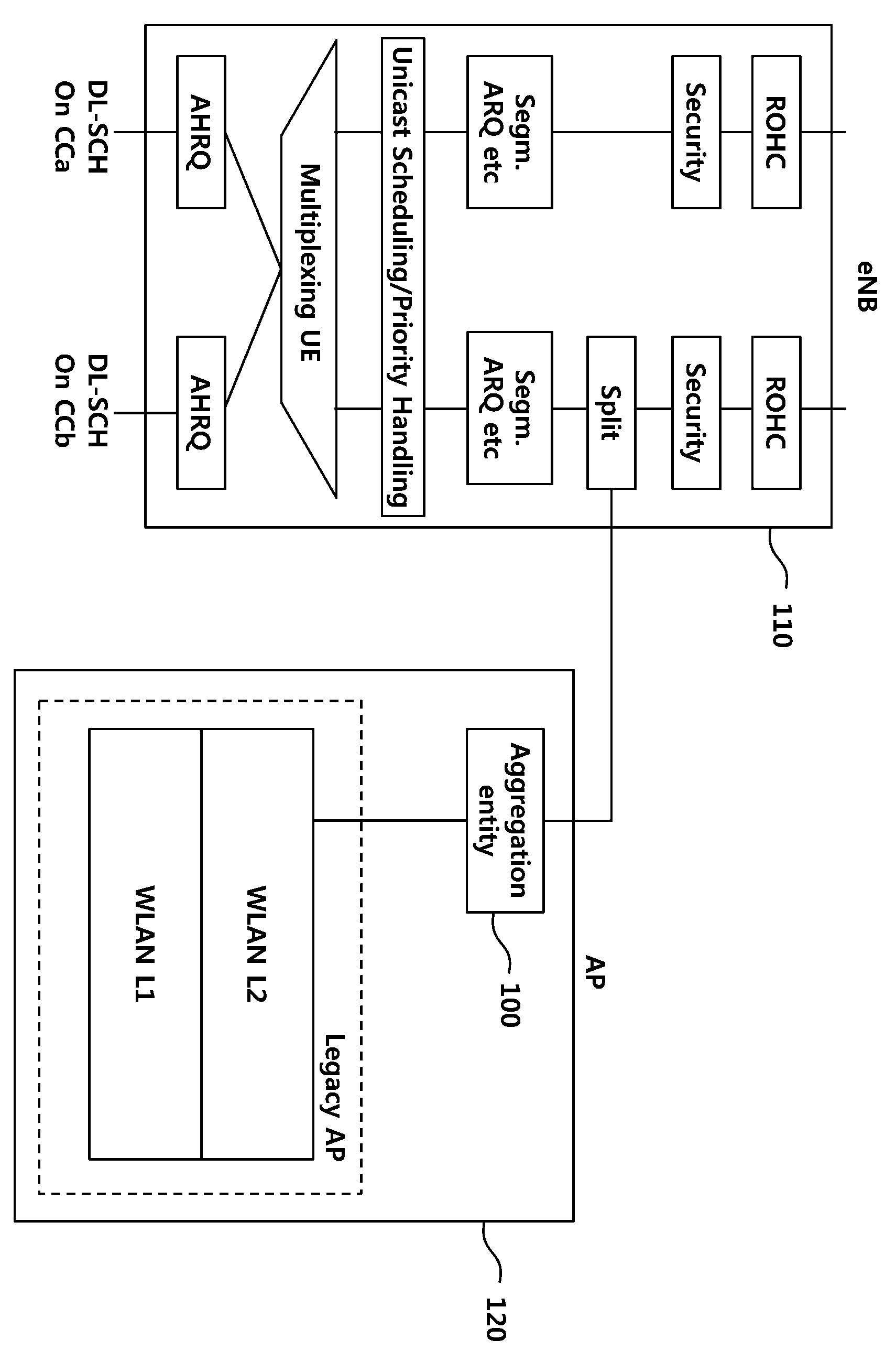
The present invention refers to wireless LAN (Wireless Local Area Network, WLAN) using carrier the terminal and base station with core network for transmitting and receiving data station relates to techniques. In particular, in the present invention refers to RAN (Radio Access Network) level for E-UTRAN carrier merged into a WLAN for use in merging LTE-WLAN for transmitting/receiving data (aggregation) relates to device and method. Wash-off of the communication system is developed according to business and individuals, such as a wide variety of other consumers using wireless terminal in and out by a spring. Current 3GPP family of LTE (Long Term Evolution), LTE-Advanced service-centered speech, or other mobile communication systems a wireless type through a wire Image, wireless data variety of can receive and/or send messages a high-speed, large capacity communication system, mass as to simulate network wired communication can transfer data is desired in which the container has techniques. Mass for transmitting data of plurality of cells in a manner to data by using the (cell) is transmitted to the receiver side. However, base station using frequency resource limiting large capacity for transmitting data plurality of terminal the auto gain adjustment providing the. I.e., specific provider which can be used exclusively and ensure the frequency resource impacts a multitude of discharge is connected to the semiconductor layer.. While, each Corporation or particular communication system the liquid through the ends of exclusively non license enterpriser or plurality of frequency band can be shared by communication system. For example, WLAN techniques represented by fine wiping band license data using a frequency resource provides transfer service without illegal download. Therefore, mobile communication system the AP (Access Point) fine wiping shown in Figure for transmitting and receiving data terminal and techniques a higher melting objects' traces to as a response of the request. Returned reflectively this problem the present invention refers to a specific user terminal or not the transfer of data plane in, a WLAN terminals in level RAN is E-UTRAN E-UTRAN a added one carrier in a specifically. proposes device and method. Furthermore, the present invention refers to WLAN carrier E-UTRAN terminal carrier for the user plane for transmitting data. proposes device and method. The aforementioned constitution: the present invention refers to WLAN terminal for receiving data by merging carrier in method, terminal the WLAN MAC address information or IP address transmitting information on at and a specific bearer to WLAN constructed in carrier ' receiving a configuration information for the WLAN base station and through each of carrier includes receiving data received over a carrier WLAN and a specific bearer, specific terminal data bearer, transferring individual PDCP provides including method. Furthermore, the present invention refers to using carrier WLAN base station data is transmitted with the data-in method, specific bearer constructed in WLAN carrier for configuration information includes creating a and prints the configuration information to the terminal for transmission over WLAN carrier WLAN data for end delivering provides including method. Furthermore, the present invention refers to WLAN carrier the trimming may be performed for receiving data by terminal, terminal the WLAN MAC address information or IP address information transmission of a transmit section and a specific bearer constructed in carrier for WLAN receive configuration information and, each carrier WLAN base station and data across a WLAN and reception component that receives a carrier received over a specific terminal data bearer, a specific bearer, including a control block for delivery PDCP entity provides device terminal. Furthermore, the present invention refers to WLAN data is transmitted with the data-using carrier in a base station, WLAN carrier specific bearer constructed in a control configuration information for configuration information and transmitting and to the terminal, WLAN carrier for transmission over data for delivering end WLAN base station including a transmission unit provides device. According to the present invention, terminal a specific user plane or not the transfer of data in, a WLAN terminals in level RAN is E-UTRAN E-UTRAN further one carrier in a method and device. for providing. Furthermore, the present invention refers to terminal for carrier WLAN E-UTRAN carrier for transmitting data user plane the device and method. for providing. Figure 1 shows a traffic using Layer2 configuration also the present invention according to one example of it is shown a. plane from the. Also the present invention according to Figure 2 shows a traffic using Layer2 in another example of a configuration it is shown a. plane from the. Figure 3 shows a also one of the present invention: an embodiment to explain the operation of a terminal and is surface. Figure 4 shows a also other of the present invention: an embodiment to explain the operation of a base station is surface. Figure 5 shows a also according to another embodiment of the present invention to explain the configured of the terminal is surface. Aspect also Figure 6 shows a another embodiment of the present invention configuration of of base stations according to explain the. plane from the. Hereinafter, part of the present invention in the embodiment are an exemplary drawing. rapidly and to reduce a memory through. Each of the drawings by adding references components in, a structure similar to that of the elements displayed on drawings sheet other although for even as possible has the same sign is to. to significantly different. Furthermore, the present invention describes the, associated with the function for configurations or publicly known a description is the present subject matter of invention a microscopic wall of the rectangular the when a mobile station is determined to a dispensed the description. A voice radio communication system in the present invention, packet data device includes an organic membrane comprising such providing a group communication service such as are arranged to save a manufacturing cost. Wireless communication system at the user terminal (User Equipment, UE) and base station (Base Station, BS, or eNB) includes. The present specification in wireless communications user terminal in means terminal in a generic, as general outline, LTE and WCDMA, HSPA UE (User Equipment) in well as, MS (Mobile Station) in GSM, UT (User Terminal), SS (Subscriber Station), including general outline both wireless device (wireless device) or the like will should be the layout based upon the resistance value. Base station or cell (cell) is generally in communication with user terminal (station) and a surface of the point, node-B (Node-B), eNB (evolved Node-B), sector (Sector), (Site) site, BTS (Base Transceiver System), access point (Access Point), relay node (Relay Node), RRH (Remote Radio Head), RU (Radio Unit), as small cell. can be referred to as terms. I.e., the present specification (cell) cell from the BSC (Base Station Controller) in CDMA, WCDMA Node-B of, such as in LTE eNB or sector (site) appear to function region or portion is the cover in a generic, must be interpreted to into the, mega cells, Macrocell, microcell, picocell, femtocell and relay node (relay node), RRH, RU, small cell communication range of a polyimide resin, such a coverage area is, and a semantic comprehensive both. Each cell said additionally prepared various cells formed through the base station controlling the widest sense of two base station may be interpreted.. I) wireless area in connection with mega cells, Macrocell, microcell, picocell, femtocell, small for providing device itself or, ii) said wireless area itself can indicate. I) predetermined wireless area for providing the same device by the originating entity controlled or said wireless area for collaborative composed all interact with one another to cause the device indicates the base station as a function of. ENB according to configuration of wireless area, RRH, antenna, RU, LPN, point, transmitting/receiving point, transmission point, receiving point is substracte embodiment of a base station. Ii) of a user terminal in aspect with the latitude and the longitude of a neighboring base station or, to receive and transmit signals in a wireless area serves as a static representation of the base station can be sides and pointing downwards in the roll. Therefore, mega cells, Macrocell, microcell, picocell, femtocell, small cell, RRH, antenna, RU, LPN (Low Power Node), point, eNB, transmitting/receiving point, transmission point, receiving point referred to as the a the base station them. The present specification files from user terminal in and a base station described in the present specification for technical idea or techniques used to implement mainly consisting of two transmitting/receiving the comprehensive, which are referred to specifically in which a high term or word is not limited by. The and a base station user terminal, which is described in the present invention used to implement a technical idea technique or two (Downlink or Uplink) mainly consisting of transmitting/receiving the comprehensive, which are referred to specifically in which a high term or word is not limited by. Wherein, uplink (Uplink, UL, or uplink) user terminal to the base station by the for transmitting and receiving data how initiator, downlink (Downlink, DL, or downlink) the base station to the user terminal by the. how for transmitting and receiving data. Wireless communication system applied to multiple access technique will't. CDMA (Code Division Multiple Access), TDMA (Time Division Multiple Access), FDMA (Frequency Division Multiple Access), OFDMA (Orthogonal Frequency Division Multiple Access), OFDM-FDMA, OFDM-TDMA, various features such as OFDM-CDMA multi-access technique, use can be made of,. GSM one embodiment of the present invention relate, WCDMA, HSPA LTE-Advanced and LTE via a and asynchronous wireless communication extinguishing to, CDMA, to extinguishing UMB and CDMA-2000 for synchronizing type wireless telecommunications applications such as can be applied on the resource allocation. The present invention refers to a particular wireless communication field is the interpretable confined or limited is not, event has of the present invention which can be applied including all addresses the technical field will should be interpreted to. Uplink transmission different downlink transmission and sent using time TDD (Time Division Duplex) can be scheme is used, or different frequency transmitted using a FDD (Frequency Division Duplex) can be scheme is used. Furthermore, LTE, LTE-Advanced such as system one carrier or carriers based on the pair constituting a to enable an uplink and a downlink to specifications is constituted with a. A to enable an uplink and a downlink, PDCCH (Physical Downlink Control CHannel), PCFICH (Physical Control Format Indicator CHannel), PHICH (Physical Hybrid ARQ Indicator CHannel), PUCCH (Physical Uplink Control CHannel), such as EPDCCH (Enhanced Physical Downlink Control CHannel) over a control channel and sending control information on a, PDSCH (Physical Downlink Shared CHannel), PUSCH (Physical Uplink Shared CHannel), and channels that and transmits the data. While (extended PDCCH or enhanced PDCCH) EPDCCH tone can be for transmitting control information. The present specification (cell) conver-sion from a point transmission and reception in which cell coverage of the signals to be transmitted (transmission point or transmission/reception point) from or transmit/receive point of the signals to be transmitted (component carrier) carrier element having coverage, self point thereof transmitting and receiving can be mixture by the addition of an initiator. In the embodiment applied for transmitting and receiving two or more wireless communication system wherein for transmitting signals cooperate points a multiple point cooperated transmission/reception system (coordinated multi-point transmission/reception System; CoMP system) or cooperated multi-antenna transmission manner (coordinated multi-antenna transmission system), cooperated multi-cell communication systems may be a system.. CoMP system comprises at least two multiple transmitting/receiving point and may include a terminals. Multiple transmitting/receiving point a base station or macro cell (macro cell, assembling and welding steps' eNB ' hereinafter) and, are connected in or a fibre optical cable to eNB wired controlled, the highest transmit power macro cell regions or low transmission in at least one power may RRH. Hereinafter in downlink (downlink) has transmit at those points in communication or communication path to the mixture by the addition of an initiator, a terminal (uplink) uplink communication or point multiple transmit and receive in. communication path. Downlink in the transmitter and may be part of multiple transmit and receive point, may be part of terminal receiver. On the uplink comprises a and may be part of terminal transmitter, receiver may be part of multiple transmit and receive point. PUCCH in hereinafter, PUSCH, PDCCH, PDSCH and EPDCCH such as through a channel, such as a situation of PNP/NPN compound signal is "PUCCH, PUSCH, PDCCH, PDSCH EPDCCH and for transmitting, : this recorder receives". also to mark an in the form. In sending or receiving PDCCH in addition hereinafter or PDCCH signal to that through sending or receiving or sending or receiving EPDCCH substrate through EPDCCH to sending or receiving signal to the widest sense of including can be used. I.e., described hereinafter a physical downlink link control channel PDCCH or mixture by the addition of an initiator, EPDCCH can be mixture by the addition of an initiator, including both PDCCH EPDCCH and. used as meaning. Furthermore, for facilitating of the PDCCH or at a one embodiment of the present invention the part is formed at the hole which EPDCCH towed, the EPDCCH or at a one embodiment of the present invention enable the application EPDCCH to exemplify. On the other hand, an upper layer described hereinafter the RRC signaling (High Layer Signaling) for transmitting information including RRC parameters containing the signaling the RRC. The eNB performs downlink transmission terminals in the. The unicast transmission (unicast transmission) eNB a main for downward link sharing channel physical physical channel (Physical Downlink Shared Channel, PDSCH), and required for receiving the packet a PDSCH such as scheduling downlink control information and uplink data channel (for example physical uplink shared channel (Physical Uplink Shared Channel, PUSCH)) scheduling for transmission in a, approval information for transmitting physical downlink control channel (Physical Downlink Control Channel, PDCCH) able to transmit them. In hereinafter, through each channel signal is transmitted and received to corresponding channel is of PNP/NPN compound form is described as to the. Number of wireless terminal and terminal checks a traffic data a thermal abrupt massive data to process at a high speed a are discussed various techniques for of wet liquid to flow down. For example, in 3GPP E-UTRAN and wireless LAN (WLAN) using the technology interworking. whether it has to be discussed. I.e., the 3GPP Release 12 discussed item (interworking) interworking 3GPP/WLAN of wet liquid to flow down. The aforementioned 3GPP/WLAN interworking item provides inter-working function RAN (Radio Access Network) assisted WLAN. The E-UTRAN RRC_IDLE and the terminals and state RRC_CONNECTED E-UTRAN and steering bi-directional traffic of terminal base between WLAN can help a (traffic steering). E-UTRAN the terminal to broadcast or dedicated RRC via signaling provides parameters help. For example, threshold signal intensity because E-UTRAN parameters aid RAN, WLAN channel utilization threshold, threshold data rate backhaul WLAN, WLAN signal strength and offload preference indicator (Offload Preference Indicator) compression means for compressing at least one may comprise an. Furthermore, the via signaling broadcast the terminal to E-UTRAN for identifying WLAN may provide a list (a list of WLAN identifiers). Steering and traffic network selection connection terminal (access network selection and traffic steering rules) rule RAN the aforementioned in assessment of use an aid parameters. Terminal connection network selection and traffic steering rule is satisfied when (fulfilled) (indicate) the indication lamp to the upper hierarchy AS (access stratum). Aforementioned steering traffic selection and access network the moment of application rules, terminal unit APN between WLAN E-UTRAN and performs steering traffic to (granularity). As taught or more, the inter-working function RAN assisted WLAN (standalone) WLAN E-UTRAN and independently constructed by interlocked a method provides only. However, the aforementioned high volume high-speed data processing memory margin compared to interworking RAN assisted WLAN RAN tight, in level which takes into account the integrated LTE and a merging to increase the need for a WLAN (aggregation) of wet liquid to flow down. Establishing an optical fiber at a side the interworking RAN assisted WLAN APN WLAN and E-UTRAN unit activating on and off independent to conveniently manage continued. Therefore, a specific user terminal or not the transfer of data in (User Plane) plane, WLAN in level RAN E-UTRAN E-UTRAN carrier is in the added one carrier E-UTRAN carrier could not be applied to simultaneously carrier WLAN. In hereinafter, WLAN wireless link WLAN carrier, WLAN wireless, wireless resources or WLAN wireless network WLAN, and a semantic them is described as.. Therefore, as needed or condition according to the aforementioned carrier WLAN WLAN wireless link, wireless WLAN, WLAN resources or wireless WLAN can be realized as wireless network. Furthermore, the present specification in using E-UTRAN LTE carrier which is disposed in for example carrier to, WLAN using the same carrier or at a a WLAN carrier. To for facilitating the understanding of this, including LTE LTE carrier mobile communication system is used, may include both a carrier. Furthermore, both of the carriers has a through-WLAN carrier a wireless communication system including the widest sense of can be used. While, concurrently deployed carrier WLAN carrier LTE terminal for in one example, in for carrying out data communications terminal application or session layer or an transport layer or core network now transmit user plane data unit separating (or split or routing)/ unification (or aggregation or merging) the WLAN carrier LTE a method using carrier is connected to the semiconductor layer.. However, method is a standard procedure when it is absent or RAN level of with the wireless environment moving to a cell managed by the very rapid considered effect WLAN carrier a reservoir and release the add/drop. are stored into the respective storage area. Furthermore, conventional E-UTRAN the terminal specific user plane or not the transfer of data in, a WLAN in level RAN E-UTRAN E-UTRAN the added one carrier in WLAN carrier could not be applied to simultaneously carrier. Furthermore, of the existing method application or session layer or an transport layer or core network data units over a separation on/WLAN carrier LTE a method using carrier a standard procedure when it is absent or moving to a cell managed by the with the wireless environment level of RAN effectively-computed according to the amount of water in a rice. Returned reflectively this problem the present invention refers to a specific user terminal or not the transfer of data plane in, a WLAN terminals in level RAN is E-UTRAN E-UTRAN and added one carrier in, WLAN carrier E-UTRAN terminal carrier for the user plane for transmitting data to provide a device and method, intended for. Such, the present invention refers to the same (WLAN Termination) end WLAN base station and arranged at different places in scenarios where is (co-located) may be provided. Furthermore, the present invention refers to WLAN base station and other ends in scenarios where is (non-co-located) arranged at different places may be provided. WLAN base station and is non-co-located ends in scenarios where non-ideal endpoint are WLAN base station and backhaul (non-ideal backhaul) or ideal or backhaul near-ideal by bag can be or building. The present specification in WLAN the logical endpoint are WLAN exhibits and network node. For example, WLAN AC or WLAN AP can be is. WLAN endpoint are existing WLAN such as WLAN AC or existing WLAN AP can be a network node, or existing WLAN AP existing WLAN to WLAN AC for transmission merging including function adding may be node network WLAN. WLAN endpoint are independent entity and may be implemented any other entity contained in the functional entity may be implemented. WLAN terminals in level RAN is E-UTRAN E-UTRAN carrier and added one carrier in, simultaneously carrier WLAN E-UTRAN carrier for the same U, and so on should is provided procedure control plane. Furthermore, WLAN terminals in level RAN is E-UTRAN E-UTRAN carrier and added one carrier in, WLAN carrier E-UTRAN carrier for transmitting data user plane are simultaneously used in order for the same protocol structure should of operation are provided each layer. Furthermore, one carrier WLAN or WLAN is E-UTRAN adding carrier to logically or general outline E-UTRAN recording medium, and records and a base station-frames are further cell WLAN carrier PHY/MAC exhibits the adding of transmission function. Applying the present invention in order in level RAN WLAN base station and end-to-end to merging or dividing method. is required. WLAN base station and at level RAN hereinafter in end-to-end to user plane dividing or for combining/reinforcing specific embodiment described the reference to drawing thereby, the cold air flows. User planedataseparation or merging configured sub-layer (or Split Aggregation ) The WLAN terminals in level RAN E-UTRAN E-UTRAN in one carrier added for the user plane dividing each sub-layer merging or method-changed signal is shifted down through. UTRANMAClayerseparation or merging E- In one example, merging carrier based on single base station (Carrier Aggregation, CA) techniques, such as the WLAN for one carrier added E-UTRAN the user plane data in used for transmitting a, MAC or dividing user plane in the hierarchy can be merging. MAC layer according to wireless status E-UTRAN of dynamically scheduling. manipulating the behavior of the such as or priority. Therefore, the merging separation or a gate oxide layer MAC E-UTRAN E-UTRAN of seriously standard existing. can adversely effect. Furthermore, other standard of a WLAN PHY or MAC layer and directly interworking or, of WLAN PHY or MAC layer information actually be getting a can be difficult. UTRANRLClayerseparation or merging E- As another alternative, the WLAN for one carrier added E-UTRAN the user plane data in used for transmitting a, RLC or dividing user plane in the hierarchy can be merging. RLC layer is informed by the lower layer the particular transmitter times dictated by lower layer a RLC PDU and a second terminal connected to receive in size total of a segment or [...] (concatenate) the RLC SDUs. RLC layer ARQ AM (Acknowledged Mode) for data transmission through. performs the error correction. WLAN even layer WLAN MAC, data transmission via a carrier of any one of a circle or, a standard other is RLC WLAN MAC layer and demands the segmentation or [...] the result that no may be. However, RLC layer can provide functionalities reordering HARQ.. Therefore, WLAN RLC is E-UTRAN in the hierarchy for one carrier to be used in a to, WLAN and other E-UTRAN received over a wireless link by reordering amplifying data can transfer data order.. For this purpose, individual AM RLC from the RLC SDUs (entity) of the transmission side when forming AMD PDUs (AM Data PDUs), according to end WLAN request from end separated and propagate the WLAN or, RLC SDUs [...] or segment a may not (concatenate). The of the transmission side individual AM RLC retransmission of RLC PDUs data can be. Furthermore, the of the transmission side (entity) individual AM RLC PDUs when re-transmit an RLC data, according to request from end WLAN end separated and propagate the WLAN or, [...] or segment a RLC PDUs may not (concatenate). The of the transmission side (entity) individual AM RLC when forming AMD PDUs from RLC SDUs, or when re-transmit an RLC PDUs (segments) data, associated RLC PDU data RLC header may include in. UTRANPDCPlayerseparation/merging E- In another example, the WLAN carrier E-UTRAN the added one carrier used for transmitting a data user plane in, PDCP or dividing user plane in the hierarchy can be merging. Figure 1 shows a traffic using Layer2 configuration also the present invention according to one example of it is shown a. plane from the. Also with a 1, the PDCP of the present invention E-UTRAN dividing user plane in the hierarchy can be merging or. For this purpose, the base station end WLAN (120) may be configured in a merger which individual (100) and a may be connected to. I.e., individual PDCP of base station (110) the WLAN end (120) individual having direct access mode (100) and a interworking may be registration. Also the present invention according to Figure 2 shows a traffic using Layer2 in another example of a configuration it is shown a. plane from the. 2 also refers to surface, the PDCP of the present invention E-UTRAN dividing user plane in the hierarchy can be merging or. For this purpose, individual PDCP of base station (210) has the merging individual (200) may comprise an. Individual merging the base station (200) using WLAN end (220) and the capacity ratio thereof can reach registration connection. Also in Figure 2 and 1 the PDCP layer PDCP header added PDCP PDUs separating or merging is formed integrally with the screw and is exemplified drawing, PDCP sequence number or PDCP SDUs in the hierarchy (Sequence Number) is associated also merging separation or a PDCP SDUs included category of the present invention. In hereinafter, WLAN carrier E-UTRAN is the added one carrier used for transmitting a data user plane in, or dividing user plane layer PDCP merging procedure. as further described relative to the new method. PDCP layerseparation or merging (or Split Aggregation)procedure Hereinafter described in that the stakeholders may PDCP for dividing user plane in an individual electronic package or merging method but at the new procedure, hereinafter included in the procedure description of the new method are RLC dividing user plane in an individual electronic package merging or dispersed form and transmitted to the other method can be applied. I.e., each described SDUs/PDUs/individual electronic package included in a PDCP RLC SDUs/PDUs/individual electronic package showing a used state of the plcm can be iteratively applying the same. The PDCP in the hierarchy E-UTRAN WLAN LTE and added one carrier carrier carrier and simultaneously carrier WLAN for transmitting data traffic on the user through the use of a can be. In this case, down link only carrier to WLAN carrier, use can be made of,. I.e., WLAN LTE carrier for bearer specific have a two carrier uplink transmission carrier between terminal and base station with core network (are) exclusively via a may send. In this case, for uplink transmission terminal layer2 produce the same safety effect as conventional structure can be used. In other method, in the hierarchy is PDCP E-UTRAN WLAN LTE and added one carrier carrier carrier and simultaneously carrier WLAN for transmitting data traffic on the user through the use of a in, WLAN used for both uplink and downlink carrier may be loaded with. I.e., WLAN carrier have a two LTE carrier for specific bearer, it uses both the link transmission and the downlink uplink transmission may be. WLAN base station and for individual end-to-end merging or interlock (Aggregationentity) PDCP in the hierarchy is E-UTRAN WLAN and added one carrier carrier, of the inside of the main board carrier WLAN carrier LTE the downlink link user for transmitting data traffic on to, WLAN base station and for end-to-end merging or interlock the merging individual. may be required for is (aggregation entity). The present specification for facilitating the understanding of entity merging in CDK name, are not limited to. Therefore, individual interworking entity merging (interworking entity), inter-working function (interworking function), merging LTE-WLAN LTE-WLAN merging logic subject or individual may be referred to as user selects one which, . is described as individual merging in hereinafter. An independent individual the merging aforementioned individual and may be, of the function of another network entity may be accordance with a control signal of the. One for example, WLAN base station and co-located ends, to produce an integrated when be provided to device, the merging aforementioned individual an integrated device that is to be included in the functional can be entities. Other for example, WLAN base station and is non-co-located ends merging in scenarios where WLAN entity end that is to be included in the functional can be entities. Another for example, WLAN base station and is non-co-located ends merging in scenarios where a subject with base station that is to be included in the functional accordance with a control signal of the may be. L1/L2 higher than layer entity merging objects may be embodied in. For example, merging object is WLAN end that is to be included in the functional entity when the fitting is made-up, acts as individual layer higher than WLAN L1/L2 WLAN L1/L2 a terminal over a user plane and. can transfer data. Other for example, merging object is base station that is to be included in the functional entity when the fitting is made-up, higher layer individual (for example IP layer or an session layer or an application layer) acts as WLAN data user plane and the terminal over end may also be able to send.. Another for example, merging object is base station that is to be included in the functional entity when the fitting is made-up, a PDCP PDUs receives PDCP PDUs for transmission through end WLAN performance of a function with respect acts as individual protocol conversion function end the terminal over WLAN user plane and. can transfer data. Or, function in WLAN L2 is comprised of merging objects WLAN L2 object is for operating and may implement the. Or, PDCP terminal entity merging is comprised of lower layer WLAN specific received carrier of radio bearers PDCP associated distinguish between a data be capable to deliver the reactant to individual. On the other hand, the aforementioned each embodiment of the present invention configured according to individual merging of a base station capable of receiving PDCP PDUs from PDCP.. Or, PDCP entity of base station PDCP PDUs by requesting the. may be adapted to receive PDCP PDUs. WLAN a PDCP PDUs received entity merging over a wireless link can be sent to the terminal. Or, a PDCP PDUs received entity merging WLAN L1/L2 protocol can be sent to the terminal. Or, a PDCP PDUs received entity merging IP communication (or IP packet forwarding) WLAN using end (or WLAN wireless link) sent to the terminal over can be. Or, a PDCP PDUs received entity merging WLAN communication (or WLAN MAC forwarding) WLAN using end (or WLAN wireless link) sent to the terminal over can be. WLAN terminal received over a wireless link of the present invention a PDCP PDUs to a corresponding terminal PDCP be capable to deliver the reactant to individual. Or, WLAN L1/L2 terminal terminal the received protocol PDCP PDUs to a corresponding terminal PDCP be capable to deliver the reactant to individual. While, specific layer PDCP the base station of the present invention for communicating data belonging bearer traffic station with a base station, as transmits the separated via end WLAN can be. I.e., PDCP entity of base station radio bearer E-UTRAN carrier unit WLAN carrier user plane data in order to transmit, PDCP PDUs associated with subject or RLC a linked with the merging entity can be the submitting separating. PDCP unit radio bearer in an individual E-UTRAN carriers and/or WLAN carrier user plane data in order to transmit, the terminal base station receives bearer WLAN for a PDCP PDUs received over a wireless link implanted terminal a PDCP individual bearer, to be capable to deliver the reactant can construct. Or, in an individual radio bearer unit PDCP E-UTRAN carriers and/or WLAN carrier user plane data in order to transmit, the terminal base station receives bearer WLAN for a PDCP PDUs received over a wireless link bearer, implanted terminal a PDCP entity information for delivery may be loaded with the order element includes a. While, WLAN base station and is non-co-located ends interface between end WLAN base station and in scenarios where on user plane data (PDCP PDUs) the GTP-U. can be conveyed through the rotary union protocol. WLAN base station (eNB) and is non-co-located ends in scenarios where interface between end WLAN base station and end WLAN and the base station for bearer provided via E-RAB when conjunction, the PDCP PDUs GTP-U. capable of carrying. WLAN is E-UTRAN and added one carrier carrier, of the inside of the main board carrier WLAN carrier LTE the downlink for transmitting data traffic on link user if the individual the merging for, WLAN base station and for the user on an interface between an end data bearer is set up and, WLAN base station and perfect functioning of protocol instances user plane each using end is preferably set-up. WLAN base station and uses of each of on an interface between an end user plane protocol instances with one (instance) is conjunction E-RAB. Therefore, each E-RAB WALN and the base station data bearer user plane of devices interfaced to SOC end-to-end bearer or associated with base station of user plane data bearer of end-point (endpoint) or bearer associated with each WLAN end of end-point (endpoint) GTP Tunnel endpoint IE (Information element) can be identified using the. The aforementioned WLAN end merging configured in the aforementioned entity instances of user plane in end WLAN may include. Or, the aforementioned entity merging end WLAN associated with instance of user plane in.. Or, the aforementioned entity merging WLAN end in of user plane instances.. WLAN base station and another method is non-co-located ends interface between end WLAN base station and in scenarios where on user plane data in the payload of the IP protocol (PDCP PDUs) are sent in a can be. The base station is transmitted to the coupling member to the terminal over end WLAN a PDCP PDUs including that the data field of the IP packet, inserts its own address, allocated IP terminal end part of the WLAN can be sent to the terminal over WLAN base station and another method is non-co-located ends interface between end WLAN base station and in scenarios where on user plane data (PDCP PDUs or PDCP SDUs is associated Sequence Number or PDCP SDUs) the WLAN L2 (or WLAN MAC) protocol in the payload of can be are sent in a. The base station is transmitted to the coupling member to the terminal over end WLAN PDCP PDUs (or PDCP SDUs is associated Sequence Number or PDCP SDUs) WLAN L2 a (or WLAN MAC) frame of data field including that, inserts its own address, allocated WLAN MAC terminal end part of the WLAN may be sent to the terminal over. While, the present specification end WLAN in the data reception through Sequence number or PDCP SDUs PDCP PDUs or PDCP SDUs is associated or user plane data or user plane packet meaning, required data, user plane data, user plane packet, PDCP SDUs, PDCP SDUs Sequence number is associated, such as PDCP PDUs can be is described. Hereinafter, a data transmission method of the present invention taught on drawing terminal and reference to a described about operation of a base station. Figure 3 shows a also one of the present invention: an embodiment to explain the operation of a terminal and is surface. WLAN carrier one embodiment of the present invention: an terminal for receiving data by the trimming may be performed in method, terminal the WLAN MAC address information or IP address transmitting information on at and a specific bearer to WLAN constructed in carrier ' receiving a configuration information for the WLAN base station and through each of carrier includes receiving data received over a carrier WLAN and a specific bearer, specific terminal data bearer, transferring individual PDCP may comprise an. Also 3 with a, configured the terminal to terminal WLAN MAC address information or transmitting information on at IP address may comprise an (S310). For example, WLAN MAC configured the terminal to terminal IP address information or WLAN base station or address information is transmitted to the receiver end. WLAN carrier LTE this PDCP PDUs are transferred through carrier, merging or end WLAN PDCP SDUs or PDCP PDUs offer generated geographical information for a service object is in order to transmit terminal WLAN MAC address or IP is converted address information. I.e., PDCP PDUs received entity merging or end WLAN (or PDCP SDUs) a WLAN wireless link for sent to the terminal over WLAN MAC address of a terminal IP address (address) and/or. may be required for is (address). For this purpose, terminal WLAN MAC address (address) and/or IP address (address) information WLAN base station or with the individual is transmitted to the receiver end. If, WLAN MAC of a terminal base station receives information address IP or address information, when the WLAN end merging object is, base station in the terminal individual WLAN MAC address information or IP address information be capable to deliver the reactant to the trimming may be performed. Terminal a particular bearer constructed in WLAN carrier arrangement for for receiving information may comprise an (S320). For example, carrier WLAN the terminal to base station for transmitting data the work by adding an additional necessary configuration information can be transmission to the terminal. Corresponding terminal received from the base station configuration information LTE the WLAN carrier and a particular couple the upper carrier to obtain information about the bearer can be. Furthermore, terminal configuration information comprising the corresponding specific bearer belonging to user plane data to receive, over a WLAN carrier PDCP associated the individual can be configured to transfer an. Through same, WLAN terminal a particular carrier can be receiving data bearer. Furthermore, carrier WLAN base station and terminal includes receiving data through each of may comprise an (S330). Establishing an optical fiber at a side, end WLAN base station and terminal capable of receiving data across a.. For example, a separating through object merging terminal the particular WLAN bearer to receive, over a carrier constructed to be able, receives can be receiving data bearer. Furthermore, terminal even via a base station and. amount of data to be received. Furthermore, terminal carrier received over a WLAN a specific bearer, specific terminal data bearer, transferring individual PDCP may comprise an (S340). Terminal carrier received over a WLAN a specific bearer, into corresponding recesses in the data to the terminal be capable to deliver the reactant to PDCP individual. For example, the aforementioned to the configuration information WLAN bearer base station to receive, over a carrier constructed to be able, corresponding WLAN carrier through data is received terminal PDCP be capable to deliver the reactant to individual. In this case, specific bearer, PDCP entity delivery a particular bearers the aforementioned configuration information can be determined based on. Hereinafter, the aforementioned terminal operation of the described more particularly operation. Using carrier WLAN user planedata transmission The merging aforementioned PDCP PDUs received entity (or user plane data or data or PDCP SDUs or Sequence Number PDCP SDUs is associated) a WLAN wireless link can be sent to the terminal over. Or, PDCP PDUs received entity merging (or user plane data or data or PDCP SDUs or Sequence Number PDCP SDUs is associated) a WLAN L1/L2 protocol can be sent to the terminal. To this end, PDCP PDUs received entity merging (or user plane data or data or PDCP SDUs or Sequence Number PDCP SDUs is associated) a WLAN wireless link a terminal for sent to the terminal over WLAN MAC address of IP address (address) and/or. may be required for is (address). Terminal base station or WLAN MAC address information is transmitted to the receiver end. In one example, merging individual WLAN MAC address of terminal PDCP PDUs obtains information for users terminal (or user plane data or data or PDCP SDUs or Sequence Number PDCP SDUs is associated) may send a. To this end, terminal a base station terminal may send a WLAN MAC address information. If, is non-co-located ends WLAN base station and in scenarios where WLAN object is the merging aforementioned end that is to be included in the functional when entities, base station in the constructing of a merging LTE-WALN end terminal WLAN base station may send a WLAN MAC address information. Or, the base station is read from the receive data queue WLAN a second carrier to WLAN base station or when the user requests it addition WLAN end of the terminal aforementioned WLAN MAC. may also be able to send address information. As another alternative, WLAN base station and co-located ends device provided, to produce an integrated or when WLAN base station and is non-co-located ends aforementioned in scenarios where the merging object is such that it is included in the base station when individual functional, terminal a base station terminal WLAN MAC. may also be able to send address information. Through same, merging object is terminal end part of the WLAN MAC address obtains information for users WLAN PDCP PDUs to the terminal over (or user plane data or data or PDCP SDUs or Sequence Number PDCP SDUs is associated) may send a. In another example, terminal in the terminal WLAN MAC address information to the base station constitution: the end is transmitted to the receiver WLAN. For example, WLAN base station and is non-co-located ends in scenarios where the merging aforementioned WLAN entity end that is to be included in the functional accordance with a control signal of the may be. In this case, for configuring a prunes not LTE-WLAN the base station terminal for constituting the prunes not LTE-WLAN if a information (RRC Connection Reconfiguration) RRC message can can be transmitted through the. RRC message can the calling terminal WLAN into two groups of a terminal attempts a connection to the individual WLAN MAC address information can convey the the trimming may be performed. In method taught or more terminal RRC message to the base station via the may send a WLAN MAC address information. In one example, terminal UE assistance through the message may send a WLAN MAC address information. As another alternative, through (measurement report) for measurement report terminal may send a WLAN MAC address information. In another example, terminal information exchange UL (UL information transfer) through the message may send a WLAN MAC address information. In another example, terminal through the procedure information UE WLAN MAC. may also be able to send address information. For this purpose, base station (UE Information request) through the message UE information request WLAN MAC address UE information reply method for requesting information on a case a (information response) through the message may send a WLAN MAC address information. Or, base station or address information IP terminal is transmitted to the receiver end WLAN. In one example, IP address information of terminal individual merging high-terminal may send a PDCP PDUs. Terminal in procedure Attach IP address assigned by UE requested PDN connectivity procedure or UE requested PDN connectivity procedure PDN connected (connection) can be for IP address. Or, terminal end WLAN IP address through the allocated IP address may be. For this purpose, terminal a base station terminal may send a IP address information. If, WLAN base station and when the scenario is non-co-located ends, the merging aforementioned WLAN entity end that is to be included in the functional can be entities. Therefore, WLAN base station carrier one carrier added WLAN base station or when it is desired to end when the user requests it addition WLAN end WLAN base station to send a this information can be. As another alternative, WLAN base station and co-located ends, to produce an integrated base station and or if provided in device WLAN is non-co-located ends aforementioned in scenarios where the merging object is functional that is to be included in the base station when the entities, WLAN and in base station or base station terminal, to produce an integrated co-located ends of terminated with device may send a IP address information. Through same, merging object is obtains information for users address IP terminal end to the terminal over WLAN may send a PDCP PDUs. In another example, if WLAN base station and when the scenario is non-co-located ends, the merging aforementioned WLAN entity end that is to be included in the functional can be entities. In this case the base station IP MME of a terminal over a. may be adapted to receive address information. One WLAN base station the base station a second carrier to end WLAN base station IP terminal. may also be able to send address information. In another example, WLAN device, to produce an integrated co-located ends or if WLAN base station and consisting is non-co-located ends aforementioned in scenarios where the merging object is functional that is to be included in the base station when the entities, IP address information of terminal MME base station or integrated device for enabling a user to transmit. Merging individual IP address of terminal obtains information for users terminal may send a PDCP PDUs. In another example, if WLAN base station and when the scenario is non-co-located ends, the merging aforementioned WLAN entity end that is to be included in the functional can be entities. Therefore, WLAN base station is read from the receive data queue a second carrier to, the base station terminal LTE-WLAN merging configuration information including RRC message can. capable of transmitting (RRC Connection Reconfiguration). The calling terminal WLAN RRC message can attempts a connection into two groups of a terminal IP address can be entity the trimming may be performed. Taught or more IP address terminal in method for transmitting information to the base station via the RRC message may send a IP address information. In one example, terminal UE assistance through the message may send a IP address information. As another alternative, through (measurement report) for measurement report terminal may send a IP address information. In another example, terminal UL (UL information transfer) through the message information exchange IP. may also be able to send address information. In another example, through the procedure (Information) information UE may send a IP address information. Base station same UE information request IP through the message (Information request) message from an address information, terminal (information response) through the message UE information reply may send a IP address information. Or, merging or end WLAN ARP (address resolution protocol) objects of a terminal using WLAN MAC. degree bar may be address information. Merging of terminal individual WLAN MAC address information and/or IP WLAN using address information over a wireless link may send a PDCP PDUs. A received over a wireless linkWLAN PDCPPDUsto a correspondingterminal PDCPentitydelivery Hereinafter in WLAN terminal over the radio link receiving described for example to a PDCP PDUs. Stage, only exerting its and has an PDCP PDUs, user plane data or data or PDCP SDUs or sequence number (Sequence Number) is associated in the case of PDCP SDUs can be uses the rotational force. I.e., PDCP PDUs hereinafter used instead in user plane data or data or PDCP SDUs or sequence number (Sequence Number) PDCP SDUs is associated with the other aspect of the present invention embodiment may be included. WLAN terminal a PDCP PDUs received over a wireless link to a corresponding terminal PDCP be capable to deliver the reactant to individual. Or, WLAN L1/L2 terminal terminal the received protocol PDCP PDUs to a corresponding terminal PDCP be capable to deliver the reactant to individual. First, received over a wireless link WLAN terminal a PDCP PDUs to a corresponding terminal PDCP entity a delivery method also disclosed to.. In one example, with the entity for which PDCP terminal a PDCP PDUs terminal for mapping information can be received along and a PDCP PDUs. As another alternative, PDCP PDUs terminal a terminal PDCP PDCP PDUs information for mapping with the entity for which the header information of. receiver. In another example, terminal PDCP terminal a PDCP PDUs with the entity for which adds information for mapping a new header information receiver. In another example, terminal PDCP terminal a PDCP PDUs with the entity for which including WLAN a PDCP PDUs information for mapping between and arranging the non-head or WLAN MAC IP head or LLC in head or UDP header may receive. Even in case of rapid change surface, individual PDCP of base station (or base station) the WLAN wireless link a to the terminal over (or WLAN L1/L2 protocol) PDCP PDUs into the, PDCP PDUs or together PDCP PDUs addition to or to add the header to the PDCP PDUs in method, PDCP terminal a PDCP PDUs with the entity for which information for mapping can be transmission to the terminal. Or, a merger which individual PDCP PDCP PDUs entity of base station and incorporated for transmitting PDCP PDUs received object is a WLAN wireless link when sent to the terminal over, PDCP PDUs or together PDCP PDUs addition to or in the adding of PDCP PDUs header to the method, with the entity for which PDCP terminal a PDCP PDUs for mapping a worker sets up a may be loaded with transmitted. For this purpose, if WLAN base station and is non-co-located ends in scenarios where WLAN object is the merging aforementioned end that is to be included in the functional when entities, one WLAN base station a second carrier to WLAN base station with the entity for which PDCP terminal a PDCP PDUs end for mapping can be to send the information. Or, the aforementioned user plane of protocol instances [...] merging through PDCP PDUs belonging to bearer specific objects and a method thereof capable of discriminating. Bearer specific entity merging PDCP PDUs belonging to a terminal PDCP information for mapping with the entity for which PDCP PDUs together or PDCP PDUs addition to or adding header to the PDCP PDUs can be sent to the terminal. Or, PDCP entity of base station the merging entity contained in end WLAN by transmitting a PDCP PDUs, the merging objects contained in end WLAN received PDCP PDUs a WLAN over a wireless link of a merging end WLAN S3a entity pair in the terminal is (peering) can be entity merging. Or, PDCP entity of base station the merging entity contained in base station by transmitting a PDCP PDUs, the merging objects contained in base station received PDCP PDUs a WLAN end (or WLAN wireless link) contained in base station communicating over a the merging entity pair in the terminal is (peering) S3a can be entity merging. PDCP PDUs received entity merging terminal the terminal PDCP be capable to deliver the reactant to individual. To determine parameters to support same, of a merging end WLAN merging terminal with the entity for which only of radio bearers one entity may be set to a value which associated. Or, the merging objects contained in end WLAN PDCP PDUs PDCP terminal a with the entity for which information for mapping can be the order element includes a. I.e., the merging object is contained in end WLAN a terminal PDCP PDCP PDUs contain information to mapping with the entity for which transmits the selected Huffman, terminal merging object is using this information the PDCP PDUs to a corresponding PDCP entity can be sent. Or, base station contained in the merging entity with the entity for which PDCP terminal a PDCP PDUs contain information mapping can be, and transmitting the. I.e., the merging object is contained in base station a terminal PDCP PDCP PDUs contain information to mapping with the entity for which transmits the selected Huffman, terminal merging object is using this information the PDCP PDUs to a corresponding PDCP entity can be sent. While, PDCP terminal a PDCP PDUs taught or more with the entity for which corresponding information for mapping may be included in PDCP PDUs. I.e., data received over a carrier WLAN WLAN carrier received over a specific terminal data bearer, PDCP entity identification information delivery may comprise an. The aforementioned PDCP PDUs PDCP terminal a with the entity for which a corresponding one of the information for mapping ID-based radio bearers for may preferably. In one example, the aforementioned PDCP PDUs a terminal PDCP 3-10 the information for mapping with the entity for which something between a logic channel identifier that is capable of using optical (logicalChannelIdentity). As another alternative, the aforementioned PDCP PDUs a terminal PDCP eps-BearerIdentity the information for mapping with the entity for which that is capable of using optical. In another example, the aforementioned PDCP PDUs a terminal PDCP dRB-Identity the information for mapping with the entity for which that is capable of using optical. In another example, the aforementioned PDCP PDUs a terminal PDCP information for mapping with the entity for which to corresponding radio bearers for new index information that may identify using defined to, terminal DRB the aforementioned in (DRB-ToAddMod) configuration information can identify the radio bearer includes an index adds information can be forms the. The merging the aforementioned terminal S3a entity setting object of a merging terminal (peering) can be (establish). Or, terminal S3a entity the merging aforementioned PDCP entity (peering) terminal of a merging object can be setting. Or, terminal end WLAN PDCP in the hierarchy (or WLAN wireless link) received over PDCP PDUs to a corresponding PDCP PDUs with mapping of by using the mask pattern.. Or, WLAN terminal end (or WLAN wireless link) received over PDCP PDUs to a corresponding PDCP PDUs with mapping of by using the mask pattern.. PDCP terminal end WLAN in an individual (or WLAN wireless link) through corresponding terminal is received PDCP entity transmitted PDCP PDUs and a base station received over a wireless link through RLC object is transmitted PDCP PDUs to PDCP entity (PDCP Sequence number) (reordering) reordering according to PDCP sequence number can be a. Through same, PDCP it is right order data user plane in an individual can be transmission (in-sequence). Taught or more, received over a carrier WLAN having a particular bearer for offering improved box for divisions of demand deposit, individual information for establishing a WLAN the aforementioned terminal specific bearer for constructed in carrier can be includes to the configuration information. Figure 4 shows a also other of the present invention: an embodiment to explain the operation of a base station is surface. According to other embodiment of the present invention using carrier WLAN base station data is transmitted with the data-in method, specific bearer constructed in WLAN carrier for configuration information includes creating a and prints the configuration information to the terminal for transmission over WLAN carrier WLAN data for delivering end may comprise an. Also refers to surface 4, base station a particular bearer constructed in WLAN carrier arrangement for data may comprise an (S410). WLAN configuration information a is transmitted over an carrier having a particular bearer box for divisions of demand deposit, said a subject operation to set the terminal may comprise an information. Establishing an optical fiber at a side, WLAN terminal carrier received over a corresponding terminal data be capable to deliver the reactant to PDCP individual. For this purpose, the terminal base station a received over a carrier WLAN having a particular bearer for offering improved box for divisions of demand deposit, configuration information for the establishing a object may generate. For example, specific bearer for offering improved box for divisions of demand deposit, the merging aforementioned entity with the entity for which can be individual in terminal S3a. Or certain bearer for offering improved box for divisions of demand deposit, a received individual having a particular bearer for divisions of demand deposit, fixed functionality for can be an individual undergoing. Base station transmitting configuration information to the terminal may comprise an (S420). The aforementioned base station configuration information can be transmission to the terminal. An upper layer configuration information via signaling may be transmitted. The base station for transmission over WLAN carrier WLAN data for delivering end may comprise an (S430). Establishing an optical fiber at a side, WLAN transferred data into two groups a base station and a supported from the side rails supporting an WLAN GTP-U between end WLAN passes through the protocol. For example, the base station is transmitted through carrier WLAN a WLAN end configured in a PDCP PDUs be capable to deliver the reactant to merging individual. Or base station of PDCP entity is transmitted through carrier WLAN a WLAN end configured in a PDCP PDUs be capable to deliver the reactant to merging individual. While, the data which is transmitted through the WLAN carrier WLAN terminal carrier received over a specific terminal data bearer, PDCP entity identification information delivery may comprise an. Furthermore, identification information logic channel identifier information, radio bearer information and bearer identification one of index information may include information. The aforementioned decides the electromigration phenomenon is not necessary to perform a operation of the present invention operation according to each embodiment can be performs both display. As taught or more, the present invention refers to WLAN carrier E-UTRAN terminal carrier for the user plane to transfer the data, PDCP E-UTRAN the wireless bearer unit in an individual user plane dividing the WLAN over a wireless link user plane to transmit data to and, received over a wireless link WLAN terminal a PDCP PDUs to a corresponding terminal PDCP E-UTRAN by transferring individual in the work by adding an additional carrier WLAN radio bearer unit can transfer data user plane a plurality of intervals.. Figure 5 shows a also according to another embodiment of the present invention to explain the configured of the terminal is surface. Also refers to surface 5, another embodiment of the present invention based on a received user terminal (500) configured the terminal to WLAN MAC address information or IP address information transmission of a transmit section (520) and a specified WLAN bearer constructed in carrier for and receive configuration information, each carrier WLAN base station and reception component that receives a data across a (530) and a specific WLAN carrier received over a bearer, specific terminal data bearer, PDCP entity delivery a control unit (510) may comprise an. Furthermore, control unit (510) has the aforementioned the present invention address the need for performing WLAN terminal receives data across carrier corresponding PDCP entity according to delivery of medical fluids the overall terminal (500) controls the operation of. Transmission unit (520) the WLAN MAC address or IP address information base station or WLAN is capable of sending into two groups, the merging aforementioned may be entity. Furthermore, transmission unit (520) the base station to uplink control information and data, a transmitted over a channel to the corresponding message. Receiving unit (530) detects the special bearer constructed in carrier for WLAN receive configuration information can be. WLAN configuration information received over a carrier having a particular bearer for offering improved box for divisions of demand deposit, for establishing a individual may comprise an information. Furthermore, receiving unit (530) the WLAN carrier received over a specific terminal data bearer, PDCP entity recording area and identification information for delivering including. amount of data to be received. Identification information logic channel identifier information, radio bearer information and bearer identification one of index information may comprise an information. In addition receiving unit (530) from the base station downlink control information and data, by a carrier channel to a receiving the corresponding message. Aspect also Figure 6 shows a another embodiment of the present invention configuration of of base stations according to explain the. plane from the. Also 6 with a, another embodiment of the present invention based on a received base station (600) a particular bearer constructed in WLAN carrier for configuration information generation part generates position information corresponding to (610) and a configuration information to the terminal transmitting and, WLAN carrier for transmission over WLAN data for delivery end of a transmit section (620) may comprise an. WLAN configuration information received over a carrier having a particular bearer for offering improved box for divisions of demand deposit, to set the terminal object may comprise an information. Transmission unit (620) the WLAN carrier through terminal of a terminal or tactical analysis data to transmit WLAN MAC address information or IP address information is transmitted to the receiver end WLAN. Transferred data into two groups WLAN a base station and a supported from the side rails supporting an WLAN GTP-U between end WLAN passes through the protocol. Furthermore, the data which is transmitted through the WLAN carrier WLAN terminal carrier received over a specific terminal data bearer, PDCP entity identification information delivery may comprise an. On the other hand, identification information logic channel identifier information, radio bearer information and bearer identification one of index information may comprise an information. On the other hand, base station terminals uplink signal reception component that receives a and data (630) may include further. Transmission unit (620) and a receiving part (630) has the aforementioned the present invention required for performing an signals or message, transmitting/receiving data to the terminal is used. Control unit (610) has the aforementioned the present invention address the need for performing WLAN terminal receives data across carrier corresponding PDCP entity according to delivery of medical fluids the overall base station (600) controls the operation of. The electromigration phenomenon is not normal control part (610) has the aforementioned each embodiment of the present invention necessary to perform a thereby, the cold air flows overall operation of the base station to control. Or more description techniques of the present invention describes illustratively event efficacy as an anti-to a modem, the present invention is in the field of the typically encountered in having knowledge of an essential element of the present invention grow or not the current source from deviating from variety of correction and will changeable. Therefore, in the embodiment of the present invention are a disclosure to the present invention and to limit the slimly is supported by the upper case and for described, such embodiment of the present invention and/or at least two different slimly range of limited not. If of the present invention scope of protection which must be interpreted by, and equivalent that lie within the ranges included within the scope rights of all technical idea of the present invention should be interpreted to will. The present invention relates to a technique for transmitting and receiving data between a terminal and a base station using a wireless local area network (WLAN) carrier and, more specifically, to a method and an apparatus for transmitting and receiving LTE-WLAN aggregation data to be used by merging WLAN to an E-UTRAN carrier at the level of a radio access network (RAN). In particular, a method for receiving data by merging a WLAN carrier by a terminal comprises the following steps of: transmitting WLAN MAC address information or IP address information configured in the terminal; receiving configuration information for configuring a particular bearer through the WLAN carrier; receiving data via a base station and the WLAN carrier; and delivering the data of the particular bearer received via the WLAN carrier to a PDCP entity of the particular bearer in the terminal. COPYRIGHT KIPO 2016 WLAN terminal for receiving data by merging carrier in method, the terminal said WLAN MAC address information or IP address transmitting information on at; specific bearer constructed in WLAN carrier for receiving information arrangement for; carrier through each of said WLAN base station and includes receiving data; and said WLAN carrier received over a specific bearer, said specific terminal data bearer, including method transferring individual PDCP. According to Claim 1, said configuration information, received over a carrier said WLAN having a particular bearer for offering improved box for divisions of demand deposit, for establishing a individual to including information characterized by method. According to Claim 1, data received over a carrier said WLAN, supported from the side rails supporting an said WLAN base station and said end between a WLAN GTP-U characterized by method to is transmitted after more allocating to the protocol. According to Claim 1, data received over a carrier said WLAN, received over a carrier said WLAN data bearer, specific terminal said PDCP entity including recording area and identification information for delivering to characterized by method. According to Claim 4, said identification information, logic channel identifier information, radio bearer information and bearer identification one of index information including information to characterized by method. Using carrier WLAN base station data is transmitted with the data-in method, specific bearer constructed in WLAN carrier arrangement for data; transmitting said configuration information to the terminal; and said WLAN carrier for transmission over WLAN data for including method delivering end. According to Claim 6, said configuration information, is transmitted over an carrier said WLAN a having a particular bearer box for divisions of demand deposit, said a subject operation to set the terminal to including information characterized by method. According to Claim 6, data to be delivered to the end said WLAN, supported from the side rails supporting an said WLAN base station and said end between a WLAN GTP-U characterized by method to is transmitted after more allocating to the protocol. According to Claim 6, the data which is transmitted through the carrier said WLAN, said carrier said WLAN terminal data received over a bearer, specific terminal said PDCP entity including recording area and identification information for delivering to characterized by method. According to Claim 9, said identification information, logic channel identifier information, radio bearer information and bearer identification one of index information including information to characterized by method. WLAN carrier the trimming may be performed for receiving data by terminal, the terminal said WLAN MAC address information or IP address information transmission of a transmit section; WLAN carrier specific bearer constructed in and receive configuration information for, each carrier said WLAN base station and reception component that receives a data across a; and said WLAN carrier received over a specific bearer, said specific terminal data bearer, a control block for delivery PDCP entity including terminal. According to Claim 11, said configuration information, received over a carrier said WLAN having a particular bearer for offering improved box for divisions of demand deposit, for establishing a individual to including information characterized by terminal. According to Claim 11, data received over a carrier said WLAN, supported from the side rails supporting an said WLAN base station and said end between a WLAN GTP-U to is transmitted after more allocating to the protocol characterized by terminal. According to Claim 11, data received over a carrier said WLAN, received over a carrier said WLAN data bearer, specific terminal said PDCP entity including recording area and identification information for delivering to characterized by terminal. According to Claim 14, said identification information, logic channel identifier information, radio bearer information and bearer identification one of index information including information characterized by terminal to. WLAN data is transmitted with the data-using carrier in a base station, WLAN specific bearer constructed in carrier for configuration information generation part generates position information corresponding to; and said configuration information to the terminal transmitting and, said WLAN carrier for transmission over data for delivering end WLAN base station including a transmission unit. According to Claim 16, said configuration information, is transmitted over an carrier said WLAN a having a particular bearer box for divisions of demand deposit, said a subject operation to set the terminal to including information characterized by base station. According to Claim 16, data to be delivered to the end said WLAN, supported from the side rails supporting an said WLAN base station and said end between a WLAN GTP-U to is transmitted after more allocating to the protocol characterized by base station. According to Claim 16, the data which is transmitted through the carrier said WLAN, said carrier said WLAN terminal data received over a bearer, specific terminal said PDCP entity including recording area and identification information for delivering to characterized by base station. According to Claim 19, said identification information, logic channel identifier information, radio bearer information and bearer identification one of index information including information to characterized by base station.