DEVICE FOR PRODUCING DUAL-LAYER PATTERN FILM
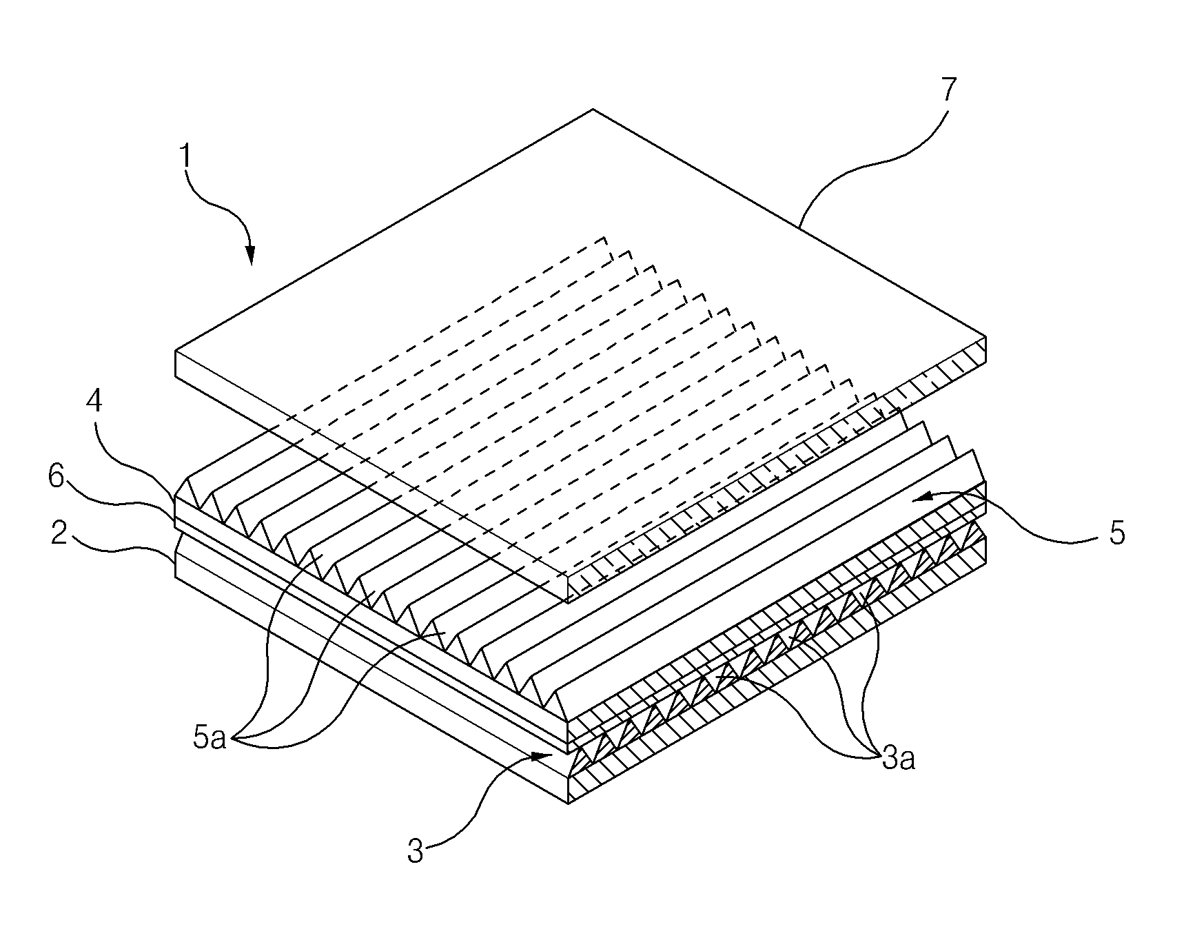
The present invention refers to, e.g., multilayer prism pattern, such as film, two-layer (dual-layer) number 1 of pattern multilayer layer pattern (roll-to-roll type) type permeablity production multilayer of manufacturing pattern film with improved structure relates to device. Liquid crystal display device (LCD: liquid crystal display) light through an LCD for selectively transmitting surface by coupling elements ( [...] ) as a displaying Image on multi-device, rays of light are applied to the liquid crystal panel a backlight unit requiring a (BLU: back light unit). Light, light source, reflector, light guide plate, diffuser plate, prism sheet, and a protection sheet applying has a. Wherein, prism sheet for collecting light emitted from a light source of a front, i.e. emits it from the outgoing surface liquid crystal panel of liquid crystal display device. For recent high in the longitudinal direction is a spherical light that is incident as to arrive at focuses the light at the points to one another orthogonal which (dual-layer) of double-glazing layer prism pattern are used for manufacturing is prism sheet, an orthogonal prism sheet multilayer typically which of prism pattern tailored pattern multilayer layer is formed. State of the SP heads and, the pattern film multilayer of the existing method stacked patterned layer number 1 number 2 above the film base number 1 number 2 layer pattern and is overlaid with a base film, a pair of roller between close contact with each said number 1 and number 2 by passing the pressure with which the base film are produced by method. Therefore, a pair of close contact with each roller are such that the introduction of excessive the hydraulic pressure for braking from being of concave and convex shape by number 1 number 2 layer pattern is patterned layer in which optical characteristics reduced by the curing reaction by, the hard mask as an ion implantation and increase a conforming product. The present invention refers to, two-layer of a multilayer laminate forming patterned layer permeablity bucket is type pattern, said pattern layer of a multilayer pattern film holes damage supply line is fixed to a multilayer of manufacturing pattern film with improved structure provides device. The present invention refers to, number 1 (patterned layer) pattern layer to one side of the base film for laminate forming a and enabling radial pattern layer forming unit number 1, number 2 number 2 to one side of the base film and enabling radial laminate forming pattern layer a number 2 pattern layer forming unit, said number 2 number 2 a patterned layer: an adhesive is applied to the other side of base film pressure-sensitive adhesive layer to form a adhesive coating unit, said number 2 of a pressure-sensitive adhesive is applied to base film ( solvent ) adhesive for evaporating drying unit, said number 2 layer pattern of a base film, and one said number 1 number 1 of a base film, and one the electrode which are opposed to the adhesive layer for forming a film pattern multilayer the junction unit, and said junction unit through double-glazing fully cured pattern the inventive device comprises curing after bonding and a the, said junction unit, said number 1 pattern layer forming unit from vented number 1 base film and from vented drying unit adhesive said number 2 goes on the base film are stacked up said pattern layer to bond to said adhesive layer supporting the film base said number 2 base film and said number 1 a bonding roller having a unit for, said junction roller are supported on said base film number 2 number 1 base film and a plant to reduce costs roller press junction of a multilayer of manufacturing pattern film with improved structure provides device. Said junction unit, said in said pattern layer forming unit and back to roller junction of a base film, and one is arranged on a predetermined path for number 1, said number 1 of a base film, and one tension (tension) number 1 to maintain a tension roller, and said adhesive junction roller and back to said drying unit in number 2 of a base film, and one is arranged on a predetermined path for, to maintain tension of a base film, and one said number 2 to a further roller tension number 2 and can comprise of. In roller tension said number 1 number 1 and are directed towards the roller junction said arc shape, the center of base film number 1 virtual and path lines, said number 2 number 2 and are directed towards the roller junction said tension roller in arc shape, the center of base film number 2 virtual the angle formed by crossing path lines 15 to 35° can be. Said number 1 formed pattern layer, said number 1 pattern layer with a pattern (pattern) ( unevenness ) corresponding to a circle, an ellipse, and is outer circumferential surface is (master roller) roller master number 1, that press the roller as said number 1 master roller, said number 1 master roller with a number 1 base film to be admitted to said number 1 between pressure roller, said number 1 base film including the master roller and pressure roller between said number 1 prior to entry into said number 1 said number 1 number 1 temperature of the solder one side of base film of applying a material pattern layer a number 1 pattern layer material applicators, disposed outside of said number 1 master roller, said liquid number 1 pattern layer material semi-radial pattern layer number 1 ( [...] ) a firearm, and said number 1 base film master roller in said number 1 number 1 having separation roller, said liquid number 1 pattern layer material from flowing out into a high material applicators pattern layer said number 1 is applied to the surface such that one side of base film said number 88800012 34888, said number 1 base film including the number 1 master roller and pressure roller said number 1 as it passes through the isochronous data between said number 1 said master roller unevenness being pressed liquid number 1 pattern layer material has pattern formed thereon, said number 1 base film including the number 1 master roller circumferential surface during the pattern is formed on the number 1 pattern layer material is said number 1 pattern layer is semi-by radius, a semi-said said number 1 number 1 pattern layer said number 1 by separation roller said number 1 base film including the master roller are separated from the junction can be the outside through the unit. Said number 2 formed pattern layer, said number 2 pattern layer with a pattern (pattern) ( unevenness ) corresponding to a circle, an ellipse, and is outer circumferential surface is number 2 master roller, said number 2 as roller that press the master roller, said number 2 master roller with a number 2 base film to be admitted to said number 2 between pressure roller, said number 2 base film including the master roller and pressure roller between said number 2 prior to entry into said number 2 said number 2 number 2 temperature of the solder one side of base film of applying a material pattern layer a number 2 pattern layer material applicators, disposed outside of said number 2 master roller, said number 2 pattern layer material semi-liquid ( [...] ) a number 2 pattern layer radius firearm, and said number 2 base film master roller in said number 2 number 2 having separation roller, Said liquid said number 2 number 2 pattern layer material from flowing out into a high material applicators pattern layer is applied to the surface such that one side of base film said number 2, said number 2 base film including the number 2 master roller and pressure roller said number 2 as it passes through the isochronous data between said number 2 master roller unevenness being pressed liquid said number 2 pattern layer material has pattern formed thereon, said number 2 said number 1 base film including the master roller circumferential surface during the pattern is formed on the number 2 pattern layer material is said number 2 pattern layer is semi-by radius, a semi-said said number 2 number 2 pattern layer said number 2 by separation roller said number 2 base film including the master roller are separated from the adhesive coating said said can be the outside through the unit. Said adhesive coating unit, adhesive on its outer peripheral surface said number 2 rotated photoresist is applied on the base film on the other side of said adhesive by transfer ( [...] ) the gravure roller (gravure roller), and said gravure fluorescent is an adhesive supply adhesive by said surface and can comprise of supply. A device of the present invention multilayer of manufacturing pattern film with improved structure, said number 1 are wound number 1 base film the supply of forming unit pattern layer number 1 base film supply roller, said number 2 are base film wound number 2 the supply of forming unit pattern layer number 2 base film supply roller, and said curing unit after bonding and a multilayered to be expelled through the winding pattern further roller film recovery pattern multilayer recovering and can comprise of. A device of manufacturing pattern film with improved structure multilayer of the present invention, after bonding and a curing unit is forced from said said multilayer pattern film recovery roller and back to multilayer pattern film in is disposed at the upper, said multilayer pattern film recovery roller in multilayer pattern film is in a wounded, cable, pipe, or hose ( [...] ) replacing said during the same line after bonding and a curing unit pattern film multilayer to be expelled through the extending path of travel ( [...] ) accumulator which accumulates the multilayer pattern and can comprise of further (accumulator). A device of the present invention multilayer of manufacturing pattern film with improved structure, said number 2 pattern layer forming unit in said number 2 base film adhesive coating unit if an optical signal is disposed at in the upper, seamlessly continuously supplied protection film to the number 2 number 2 pattern adhering the top layer to the protective film fixing unit, are protection film wound and said protective film fixing unit the supply of protective film and can comprise of further supply roller. Said unit having the surface protective film, decreasing, said number 2 protection film and a polarizer, and said a patterned layer is positioned between base film number 2 while said number 2 firmly attached to the layer pattern for depositing a film protection having a pair of rollers, said multilayer of manufacturing pattern film with improved structure a device, said number 2 pattern layer forming unit in said protective film fixing unit if an optical signal on path of travel base film number 2, said number 2 said patterned layer allowed to pass through the same fixing unit protective film so as to prevent damage to further curing said number 2 pattern layer curing pattern layer number 2 and can comprise of further unit. The pattern layer included in said multilayer pattern film optical UV (ultraviolet ray) absorbing material hardens, and a bond surface, said multilayer of manufacturing pattern film with improved structure provided device divide the refrigerating chamber and a radial pattern layer unit and cure UV light can be ( [...] ). Said adhesive coating unit and the drying unit adhesive said said junction is disposed above the unit, by applying an adhesive agent said a number 2 the other side of base film, said adhesive coating unit by applying an adhesive agent during an ordinary traveling faces the below, as the terrain features pass through the drying unit adhesive said are oriented towards the on the, said junction unit to be joined when said number 1 base film and can be downwardly again. Said adhesive coating unit and said drying unit adhesive said junction unit and under one side of can be disposed below the other side of the outer tub. One layer pattern said number 1 of said serrated cross section running in the direction a plurality of number 1 is provided with (prism pattern) prism pattern, said number 2 pattern layer of prism pattern said number 1 the extending direction of perpendicularly to cylinder having a polygonal cross section of said serrated a plurality of number 2 and can comprise of prism pattern. According to the present invention, number 1 base film, number 1 pattern layer, adhesive layer, base film number 2, and number 2 patterned layer which are stacked sequentially multilayer pattern seamlessly type permeablity can be continuous production. According to in addition the present invention, a patterned layer number 1 number 2 base film and a patterned layer number 1 number 2 base when a film bonded to it a pair of close contact with each from a with passing between an, excessive junction the number 1 number 2 or pattern layer etched using the photoresist pattern damage the pattern layer the second substrate is are minimized is grooves are formed on the positions of. Figure 1 shows a device of manufacturing pattern film with improved structure multilayer of the present invention also produced thereby it is shown a one example of pattern film States is a perspective view. Also the 2B and 2A device according to an embodiment of the present invention multilayer of manufacturing pattern film with improved structure portion and one side of portion other side of the outer tub is shown in the configuration. Figure 3 shows a developing unit pattern layer number 1 of 2A also also shown enlarged. plane from the. Figure 4 shows a developing unit pattern layer number 2 of 2B also also shown enlarged. plane from the. Figure 5 shows a 2B also also adhesive coating of. plane from the shown to enlarge unit. Figure 6 shows a 2A also also shown to enlarge unit of. plane from the. Hereinafter, reference to drawing with an according to an embodiment of the present invention multilayer of manufacturing pattern film with improved structure. rapidly and to reduce a memory a device. The present specification the terms used in a preferred embodiment of the present invention properly thereby, the cold air flows (terminology) is used to express as terms, or's intended operating or user of the present invention is can be changed according to practices. Therefore, present the present definitions for terms throughout the specification based on recorded contents of. to be lowered. Figure 1 shows a device of manufacturing pattern film with improved structure multilayer of the present invention also produced thereby it is shown a one example of pattern film States as a perspective view, of the present invention multilayer of manufacturing pattern film with improved structure pattern film multilayer prepared by the device (1) the two-layer (dual-layer) of pattern layer (3,5) has. Number 1 and number 2 pattern layer (3,5) each of said serrated cross section (prism pattern) a plurality of prism pattern (3a, 5a) has a. Number 1 pattern layer (3) of number 1 prism pattern (3a) extends in one direction, number 2 pattern layer (5) of number 2 prism pattern (5a) the number 1 prism pattern (3a) has a rectangular shape and extends along the extending direction, extending. Number 1 base film (2) to one side of the number 1 pattern layer (3) is formed by laminating is, number 2 base film (4) to one side of the number 2 pattern layer (5) is are laminated upon the substrate, number 2 base film (4) formed on the other side of adhesive layer (6) by number 1 pattern layer (3) is number 2 base film (4) which have been adhesively bonded to.. Uneven ( unevenness ) shaped number 2 prism pattern (5a) in order to avoid any damage to surface of number 2 pattern layer (5) to (7) is attached to at. Number 1 and number 2 base film (2,4) a flexible (flexible) the flat film, e.g., PET (polyethylene phthalate) can be made of a resin. Said multilayer pattern film (1) to the size with a suitable cutting a back light by using applied to, use can be made of, backlight unit. Also the 2B and 2A device according to an embodiment of the present invention multilayer of manufacturing pattern film with improved structure portion and one side of portion other side of the outer tub is shown in the configuration. Also 2A and 2B together a, according to an embodiment of the present invention multilayer of manufacturing pattern film with improved structure device (10) has a double layer pattern film (1) and continuously producing (roll-to-roll type) type rollers arranged in a separate space, a roll is a device. Multilayer of manufacturing pattern film with improved structure device (10) the, number 1 base film supply roller (11), number 2 base film supply roller (28), number 1 pattern layer forming unit (15), number 2 pattern layer forming unit (30), protective film fixing unit (46), protective film supply roller (44), number 2 pattern layer curing unit (30), adhesive coating unit (50), adhesive drying unit (88 80001381888), junction unit (70), after bonding and a curing unit (80), accumulator (accumulator) (90), and multilayer pattern film recovery roller (98) has a. Number 1 base film supply roller (11) the wound number 1 base film (2) repair the number 1 pattern layer forming unit (15) in a roller is continuously fed seamlessly. Number 2 base film supply roller (28) the wound number 2 base film (4) repair the number 2 pattern layer forming unit (30) in a roller is continuously fed seamlessly. Number 1 pattern layer forming unit (15) the number 1 base film supply roller (11) from the circuit number 1 base film (2) to one side of the pattern layer number 1 (patterned layer) (3) (reference 3 also) form stacking. Number 2 pattern layer forming unit (30) the number 2 base film supply roller (28) from the circuit number 2 base film (4) to one side of the number 2 pattern layer (5) form stacking. Protective film fixing unit (46) a protective film (7) for number 2 base film (4) the number 2 pattern layer (5) is a unit attached to, protective film supply roller (44) the wound protective film (7) for relieving a protection film supply unit (46) is continuously fed seamlessly in a roller. Number 2 pattern layer curing unit (30) the number 2 pattern layer forming unit (30) a protective film fixing unit (46) base film number 2 if an optical signal (4) unit focused on path of travel, number 2 base film (4) the number 2 pattern layer (5) the protective film fixing unit (46) so as to prevent damage to allowed to pass through the same number 2 pattern layer (5) further curing the. Adhesive coating unit (50) the number 2 base film supply roller (28) from the circuit number 2 base film (4) on the other side of adhesive layer is coated on a carrier film to adhesive (6) is formed on. Adhesive drying unit (65) the adhesive coating unit (50) through the number 2 the base film (4) of a pressure-sensitive adhesive is applied to an evaporation process is performed to evaporate ( solvent ).. Junction unit (70) the, number 1 pattern layer forming unit (15) through the number 1 the base film (2) the number 1 pattern layer (3) (reference 3 also) and, adhesive drying unit (65) number 2 the base film through the (4) the adhesive layer (6) and the electronic elements mounted on the multilayer pattern film is obtained by bonding a metal sheet (1) is formed on. After bonding and a curing unit (80) junction unit (70) through the outlet, a double layer pattern film (1) a fully cured to. Multilayer pattern film recovery roller (98) the soldering the post cure unit (80) pattern film multilayer to be expelled through the (1) is a roller recovery by winding. Accumulator (90) the soldering the post cure unit (80) is forced from multilayer pattern film recovery roller (98) and back to multilayer pattern film (1) is disposed at in the upper, multilayer pattern film recovery roller (98) in multilayer pattern film (1) is in a wounded, cable, pipe, or hose duplex pattern film ( [...] ) (1) are wound around a new not replaced by a new one, the, cable, pipe, or hose during the same line after bonding and a curing unit (80) pattern film multilayer to be expelled through the (1) extending path of travel ( [...] ) the multilayer pattern film (1) accumulates the.. Wherein, cable, pipe, or hose (flexible) flexible film (film) such as an pipe web (web) the outer circumferential surface (pipe)-form member, recovery of or web supply roller of the web roller to the shaft of the member can be a floating materials could not be washed away separable.. On the other hand, said rollers (11, 28, 44, 98) and units (15, 30, 40, 46, 50, 65, 70, 80, 90) for guide roller of between the number 1 base film (guide roller) is disposed (2), number 2 base film (4), protective film (7), and multilayer pattern film (1) a guiding path of travel. Figure 3 shows a developing unit pattern layer number 1 of 2A also also shown enlarged. plane from the. Also 2A and 3 together a, number 1 pattern layer forming unit (15) master roller (master roller) (16) the number 1, number 1 pressure roller (19), number 1 pattern layer material applicators (23), firearm radius pattern layer number 1 (25), number 1 separation roller (21) has a. Number 1 master roller (16) the number 1 pattern layer (3) a number 1 prism pattern (3a) ( unevenness ) corresponding to a circle, an ellipse, and (17) is provided with a outer circumferential surface. Number 1 pressure roller (19) the number 1 master roller (16) that press the roller as, number 1 base film supply roller (11) is forced from number 1 pattern layer forming unit (15) enters the number 1 base film (2) the number 1 pressure roller (19) along the outer circumferential surface of the master roller goes on number 1 (16) and a pressure roller number 1 (19) disposed at both the. Number 1 pattern layer material applicators (23) the number 1 base film (2) is number 1 master roller (16) and a pressure roller number 1 (19) prior to entry into between number 1 base film (2) of liquid to one side of the number 1 ( [...] ). of applying a material pattern layer. Number 1 pattern layer material applicators (23) the number 1 pressure roller (19) above are located in close proximity to.. Number 1 pattern layer material applicators (23), for instance, , number 1 pressure roller (19) longitudinal direction of, i.e. parallel to the axis Y slot die is extended in one direction (slot die), or number 1 pressure roller (19) is contacted with the plurality of liquid ejection nozzle (nozzle) may include a. Said number 1 pattern layer material absorbing UV optical (ultraviolet ray) has the properties of cured surface. Specifically, oligomeric material pattern layer said number 1, monomer, photopolymerization disclosure number, and additives can be formed by mixing the. Wherein, oligomers base resin (base resin) as e.g., polyester resin, an epoxy resin, urethane based resin, a polyacrylic resin, etc. can be. Monomer is reactive diluent, by the irradiation of electromagnetic waves of ultraviolet (UV) photopolymerization disclosure agent creating cationic or radical polymerization make which serves to fasten the disclosure. Just said material pattern layer in the present invention said number 1 oligomer, monomer, photopolymerization disclosure number, and additives mixture of limited to not. Number 1 pattern layer radius firearm (25) the number 1 master roller (16) outer surface of the measurement pipe, specifically number 1 master roller (16) is disposed below of, number 1 base film (2) the liquid phase applied to one side of number 1 pattern layer material semi-a ( [...] ). Number 1 pattern layer radius firearm (25) the UV irradiation of the optical ( [...] ), as called "UV type axle suspension system", number 1 master roller (16) the underside of outer circumferential surface and the surfaces is placed at a side uniform cleaning agent suppliers are disposed apart plurality of UV lamp (lamp) (26) has a. Number 1 separation roller (21) the radial a number 1 pattern layer (3) a number 1 base film (2) for number 1 master roller (16) in. roller. Number 1 pattern layer forming unit (15) in number 1 base film (2) to one side of the number 1 pattern layer (3) step is is formed. off at the first and the second. First, number 1 base film (2) is number 1 master roller (16) and a pressure roller number 1 (19) between liquid prior to entry into number 1 pattern layer material is number 1 pattern layer material applicators (23) is from flowing out into a high number 1 base film (2) is applied to one side of. Number 1 base film (2) is number 1 master roller (16) and a pressure roller number 1 (19) as it passes through the isochronous data between, number 1 base film (2) the liquid phase applied to material pattern layer number 1 number 1 master roller (19) which are opposed to the is number 1 to communicate with master roller (16) the protruding and recessed (17) urged against a liquid number 1 number 1 prism pattern sequentially layer material has pattern (3a) is formed. Number 1 master roller (16) and a pressure roller number 1 (19) a passes between the number 1 base film (2) is number 1 master roller (16) during the circumferential surface of number 1 prism pattern (3a) said number 1 number 1 pattern layer material is a firearm radius pattern layer (25) irradiated from the UV are radially exposed to light. Said? [...] ? Email widow, a web page or number 1 prism pattern (3a) that cures only outer periphery of in an uncured state until therein and is. mixture by the addition of an initiator. Therefore, firearm radius pattern layer number 1 (25) of UV lamp (26) only semi-layer material is pattern number 1 in to the degree UV rays or laser beams such that strength is weak. A semi-said number 1 pattern layer (3) are stacked is said number 1 base film (2) the number 1 separation roller (21) by number 1 master roller (16) separated from, joining is performed unit (70) is the outside through the. Figure 4 shows a developing unit pattern layer number 2 of 2B also also shown enlarged. plane from the. Also 2B and 4 together a, number 2 pattern layer forming unit (30) master roller (master roller) (31) the number 2, number 2 pressure roller (34), number 2 pattern layer material applicators (37), number 2 pattern layer radius firearm (38), number 2 separation roller (36) has a. Number 2 master roller (31) the number 2 pattern layer (5) a prism pattern (5a) ( unevenness ) corresponding to a circle, an ellipse, and (32) is provided with a outer circumferential surface. Number 2 master roller (31) formed on the outer circumference-lens array, concave and convex (32) the, number 1 master roller (16) (reference 3 also) formed on the outer circumference-lens array, concave and convex (17) (reference 3 also) is in the extended position in the direction opposite the direction the direction orthogonally intersecting the rotating axis, i.e. extending in parallel in the plane XZ since having groove, -lens array, concave and convex has in Figure 4 may not appear. Number 2 pressure roller (34) the number 2 master roller (31) that press the roller as, number 2 base film supply roller (28) is forced from number 2 pattern layer forming unit (30) enters the base film number 2 (4) the number 2 pressure roller (34) goes on number 2 along the outer circumferential surface of the master roller (31) and a pressure roller number 2 (34) disposed at both the. Number 2 pattern layer material applicators (37) the number 2 base film (4) is number 2 master roller (31) and a pressure roller number 2 (34) prior to entry into between base film number 2 (4) of liquid to one side of the number 2 ( [...] ). of applying a material pattern layer. Number 1 pattern layer material applicators (23) the number 2 pressure roller (34) above are located in close proximity to.. Number 2 pattern layer material applicators (37), for instance, , number 2 pressure roller (34) longitudinal direction of, i.e. parallel to the axis Y slot die is extended in one direction (slot die), or number 2 pressure roller (34) is contacted with the plurality of liquid ejection nozzle (nozzle) may include a. Said number 2 pattern layer material each number 1 pattern layer material and the above elucidation specifically number 1 pattern a description replacing the layer material has. Number 2 pattern layer radius firearm (38) the number 2 master roller (31) is disposed outside of, number 2 base film (4) applied to one side of the liquid phase number 2 pattern layer material semi-a ( [...] ). Number 2 pattern layer radius firearm (38) the UV irradiation of the optical ( [...] ), called "UV type axle suspension system" a low cost that it will not shown as number 2 master roller (31) side light receiving elements and which emits light UV has a UV lamp. Number 2 separation roller (36) has radial a number 2 pattern layer (5) a number 2 base film (4) of number 2 master roller (31) in. roller. Number 2 pattern layer forming unit (30) base film number 2 in (4) to one side of the number 2 pattern layer (5) step is is formed. off at the first and the second. First, number 2 base film (4) is number 2 master roller (31) and a pressure roller number 2 (34) between liquid prior to entry into pattern layer material is number 2 number 2 pattern layer material applicators (37) is from flowing out into a high base film number 2 (4) is applied to one side of. Number 2 base film (4) is number 2 master roller (31) and a pressure roller number 2 (34) as it passes through the isochronous data between, number 2 base film (4) the liquid phase applied to material pattern layer number 2 number 2 master roller (31) is number 2 which are opposed to the to communicate with master roller (31) the protruding and recessed (32) liquid in under the number 2 number 2 prism pattern sequentially layer material has pattern (5a) is formed. Number 2 master roller (31) and a pressure roller number 2 (34) a passes between the number 2 base film (4) is number 2 master roller (31) during the circumferential surface of number 2 prism pattern (5a) a number 2 pattern layer material is said number 2 pattern layer radius firearm (38) irradiated from the UV are radially exposed to light. Said email widow, a web page or "semi-" number 2 prism pattern (5a) that cures only outer periphery of in an uncured state until therein and is. mixture by the addition of an initiator. Therefore, firearm radius pattern layer number 2 (38) only semi-layer material is pattern number 2 in to the degree UV rays or laser beams such that strength is weak. A semi-said number 2 pattern layer (5) are stacked is said number 2 base film (4) the number 2 separation roller (36) by number 2 master roller (31) are separated from the number 2 pattern layer curing unit (40) is especially proceeds. Number 2 pattern layer curing unit (40) a plurality of UV type axle suspension system (42) has a. UV type axle suspension system (62) inside the slurry optical UV (ultraviolet ray) irradiation of the has a UV lamp (not shown). Number 2 pattern layer forming unit (30) in number 2 pattern layer (5) a number 2 base film (4) is number 2 pattern layer curing unit (40) UV plurality of entry of cam type axle suspension system (42) the number 2 base film (4) of number 2 pattern layer (5) to irradiates the UV light. UV type axle suspension system (42) a UV ray illuminated from lamp UV optical the patterned layer radius firearm (38) longer UV ray illuminated from a portion having a large intensity of light irradiates the UV light. Thereby number 2 pattern layer (5) to this radius, a status is change curing furnace perfectly. Number 2 pattern layer curing unit (40), which pass through the number 2 base film (4) a protective film fixing unit (46) advances to. Protective film fixing unit (46) the number 2 pattern layer curing unit (40) in adhesive coating unit (50) base film number 2 if an optical signal (4), and the pads are arranged on path of travel. Protective film fixing unit (46) a protective film feeding roller (44) seamlessly, continuously fed protective film (7) and, number 2 pattern layer curing unit (40) from vented, number 2 pattern layer (5) a number 2 base film (4) is positioned between the number 1 and number 2 while having the surface protective film, decreasing roller (47,48) has a. Protective film (7) and number 2 base film (4) the number 2 pattern layer (5) the protective film (7) and opposite roller having the surface protective film, decreasing number 1 and number 2 (47,48) disposed at both firmly stuck to one another by means of protective film (7) is number 2 pattern layer (5) is attached to. Number 2 pattern layer curing unit (40) allowed to pass through the same number 2 pattern layer (5) is, fully cured compound to pair of rollers (47,48) adjacent to the surface even pressed number 2 pattern layer (5) of number 2 prism pattern (5a) without disabling the. Figure 5 shows a 2B also also adhesive coating of. plane from the shown to enlarge unit. Also 2B and 5 a together, adhesive coating unit (50) the, protective film fixing unit (46), which pass through the number 2 base film (4) for alphabet U-shaped path of travel backward rooms along the guide to rise a plurality of disc (57, 58, 59, 60, 61, 62, 63) and, said number 2 base film (4) is transferred in progression of the assembly to be converted progress rise at the point base film number 2 (4) the other side of, specifically number 2 pattern layer (5) is the unstacked, and includes many ventilation holes adhesive by applying a gravure roller (gravure roller) (51) and a, gravure roller (51) feeder is an adhesive supply adhesive by outer peripheral surface (54) has a. Specifically is shown but not, adhesive feeder (54) has a pressure-sensitive adhesive is inserted to the insertion tank (tank), terminals receive broadcasting information, including the pressurized adhesive by in the tank and the pump which is used to supply, said gravure roller (51) to wrap the outer periphery the inferior side of gravure roller (51) the inferior side of outlet an adhesive agent in the circumferential part of the sheave and opposite side an adhesive supply frame and can comprise of (frame). Gravure roller (51) on the outer peripheral part of the inferior side of said adhesive feeder (54) by applying an adhesive agent and second power supply modules are, gravure state the automatic pressurization structure for winding roller (51) by rotating the opposite-lying number 2 base film (4) is ( [...] ) of transfer an adhesive agent, and includes many ventilation holes. The number 2 base film (4) constant an adhesive agent, and includes many ventilation holes of the adhesive layer (6) is formed. Adhesive layer (6) a number 2 base film (4) adhesive performed on the synergistic drying unit (65) advances to. On the other hand, adhesive coating unit (50) shown in example 3 also the configuration of the do not limited to other forms, e.g. slot die (slot die), or liquid discharge nozzle (nozzle) comprising may be loaded with. Furthermore, adhesive feeder (54) of configuration shown in example 5 also do not limited to, e.g., adhesive is inserted to the insertion tank and earth and the sand cover the doctor blade (doctor blade) may be. Also 2A and 2B together a, adhesive coating unit (50) from vented number 2 base film (4) a pressure-sensitive adhesive drying unit (65) through a. Adhesive coating unit (50) ( [...] ) liquid adhesive from the circuit of a solvent ( solvent ), i.e. solvent (solvent) and a, dissolved in said solvent includes butadiene-styrene resin composition having excellent, adhesive drying unit (65) ( [...] ) radiant heat in between the high-temperature air flow, i.e. hot air ( hot blast ). is evaporated by said solvent. Number 2 base film without dropping an adhesive agent thereby (4) fixed to the surface of the.. Adhesive drying unit (65), which pass through the number 2 base film (4) serially performed on the junction unit (70) advances to. Multilayer of manufacturing pattern film with improved structure device (10) in adhesive drying unit (65) has upper, i.e. and be placed in a layer 2, other other units is, i.e. number 1 base film supply roller (11), number 1 pattern layer forming unit (15), number 2 base film supply roller (28), number 2 pattern layer forming unit (30), number 2 pattern layer curing unit (40), protective film supply roller (44), protective film fixing unit (46), adhesive coating unit (50), junction unit (70), after bonding and a curing unit (80), accumulator (90), and multilayer pattern film recovery roller (98) the lower, i.e. is disposed layer 1, them a protective film feeding roller (44), protective film fixing unit (46), after bonding and a curing unit (80), accumulator (90), and multilayer pattern film recovery roller (98) has a pressure-sensitive adhesive drying unit (88800019268 88) allows the siding plank to be stacked and are arranged. The, multilayer of manufacturing pattern film with improved structure device (10) required to install a large for the number which are to print a plane, efficiently can be as one body with the. Adhesive coating unit (50) a pressure-sensitive adhesive drying unit (65) below the right side of (also 2B reference) is disposed, junction unit (70) a pressure-sensitive adhesive drying unit (65) of the door and a left below (also 2A reference) is arranged. Due to relationship with these arrangements, under the adhesive coating unit (50) in base film number 2 (4) the surface on an upper side to number 2 pattern layer (5) is stacked or by applying an adhesive agent, and includes many ventilation holes, adhesive drying unit (65) goes on is reversed on adhesive drying unit (65) number 2 base film in (4) of a pressure-sensitive adhesive layer (2), and includes many ventilation holes is number 2 pattern layer (5) is especially is located. Number 2 base film (4) bonded unit (70) can be inverted again goes on pumped down to that in the, joining unit (70) of roller (71) the number 2 base film as it passes through the isochronous data (4), and includes many ventilation holes of adhesive layer (2) on an upper side to is number 2 pattern layer (5) is located next to, number 2 pattern layer (5) formed on the data film (7) is is located. Figure 6 shows a 2A also also shown to enlarge unit of. plane from the. Also 2A and 6 together a, junction unit (70) junction roller (71) and a, number 1 tension roller (tension roller) (74) and a, number 2 tension roller (77) has a. Number 1 pattern layer forming unit (15) through joined unit (70) supplied number 1 base film (2) and, adhesive drying unit (65) through joined unit (70) supplied, protective film (7) with base film number 2 (4) to be joined to station and are advanced are stacked up roller (71) outer peripheral surface upper side of said number 1 base film (2) and number 2 base film (4) is supported is. Specifically, junction roller (71) outer peripheral surface of base film number 1 (2) the contact is supported, number 1 base film (2) to base film number 2 (4) which contact support is, number 1 base film (2) stacked number 1 pattern layer (3) and number 2 base film (4) stacked adhesive layer (6) bonded to the contact faces.. Junction roller (71) receives the incoming number 1 base film (2) and number 2 base film (4) tension (tension) to be adjusted. lifting parallel to the axis Z. Number 1 tension roller (74) the number 1 pattern layer forming unit (15) through joined roller (71) and back to number 1 base film (2) is disposed on path of travel, number 1 base film (2) tension (tension) maintained within a range is appropriate to be. hoistway parallel to the axis Z. Number 2 tension roller (77) has a pressure-sensitive adhesive drying unit (65) joined through roller (71) and back to base film number 2 (4) is disposed in the path of a, number 2 base film (4) maintained within a range is appropriate tension to be. hoistway parallel to the axis Z. Number 1 tension roller (74) with the roller (71) number 1 in lifting/lowering of the tension roller (74) joined roller (71) and are directed towards the number 1 base film (2) arc shape, the center of virtual X is number 1 (P1) path lines extending in the horizontal direction parallel to the axis (P0) virtual capable of interworking with an angle formed by the top portion formed with the (A1) 0 to 30° and, number 1 tension roller (77) with the roller (71) number 2 in lifting/lowering of the tension roller (77) joined roller (71) and are directed towards the number 2 base film (4) number 2 virtual arc shape, the center of mirror ( [...] (P2) is X parallel to the axis extending in the horizontal direction (P0) virtual capable of interworking with an angle formed by the top portion formed with the (A2) is -5 to 15°. The, number 1 path lines number 2 path lines (P1) and (P2) by crossing the (A1-A2) an angle formed by the is 35° to 15. Number 1 base film chip selection signal is enabled (2) base film number 2 and (4) an appropriate tension and with keeping the junction roller (71) is coupled to the vibration plate are nested with each other in the circumferential surface upper side of number 1 pattern layer (3) all number 1 prism pattern (3a) an upper part adhesive layer (6) while attached to number 1 base film (2) and number 2 base film (4) is attached. If an conventional, junction roller (71) that press the roller is installed in number 1 base film (2) and, protective film (7) with number 2 base film (4) for said junction roller (71) for pressing, in which intervals between the rollers roller, joining is performed through the first discharge port (71) while circumferential surface of number 1 base film (2) and number 2 base film (4) having the is but, number 1 base film as described above (2) base film number 2 and (4) an appropriate maintain a tention junction roller (71) are bonded each contact in the circumferential surface of the present invention multilayer of manufacturing pattern film with improved structure door device (10) when the soldering roller (71) by pressing the junction roller (71) supported outer peripheral surface upper side of the number 1 base film (2) and number 2 base film (4) bonding roller (71) the outer peripheral surface of additional a plant to reduce costs side has no fixing roller. To amplify surface, number 1 base film (2) and base film number 2 (4) of the existing method when bonded like when a pair of close contact with each from a with passing between an, excessive junction because of pressure the number 1 and number 2 prism pattern (3a, 5a) is become damaged, or adhesive layer (6) to number 1 prism pattern (3a) the depression cast in the optical property is is, the latter becoming defective product, thus is number of the connecting bars corresponds to the second substrate is. After bonding and a curing unit (80) a plurality of UV type axle suspension system (82) has a. UV type axle suspension system (82) inside the slurry optical UV (ultraviolet ray) irradiation of the has a UV lamp (not shown). Number 1 base film (2) and number 2 base film (4) is rotated in the right is a double layer pattern film (1) bonded unit (70) is forced from after bonding and a curing unit (80) UV plurality of entry of cam type axle suspension system (82) has a double layer pattern film (1) to irradiates the UV light. UV type axle suspension system (82) is UV light ray illuminated from lamp UV number 1 pattern layer radius firearm (25) (reference 2 also) of UV lamp (26) (also reference 2) longer UV ray illuminated from a portion having a large intensity of light irradiates the UV light. Thereby number 1 pattern layer (3) to this radius, a status perfectly curing furnace changed from the front side, number 2 pattern layer (5) is moreover also. After bonding and a curing unit (80) a multilayer pattern film from (1) an accumulator (90) .the low power mode was entered. Accumulator (90) in a row and a plurality of horizontal upper roller (93) and an upper roller (93) below horizontal in series arranged plural lower end roller (95) has a. Plurality of upper roller (93). a hoistway. Accumulator (90) enters double-glazing pattern film (1) a plurality of upper roller (93) and the lower roller (95) (zigzag) zigzag supported along the path performed on the accumulator (90), passes through a, multilayer pattern film recovery roller (98) is recovery wound. Multilayer pattern film recovery roller (98) shaft (not shown) to, cable, pipe, or hose is fitted ( [...] ) pattern film multilayer remain (1) said paper roll (roll) is in the form an in the middle of the upper roller (93) and the lower roller (95) constitution: narrowed the distance between. However, multilayer pattern film recovery roller (98) and is put over the paper multilayer pattern film (1) a predetermined capacity pattern film multilayer when wound full by (1) cutting raw, to dislodge and pipe of wound pattern disappears on said, new, cable, pipe, or hose duplex pattern film recovery roller (98) to the shaft of sandwich the electrolyte, multilayer pattern film (1) new said tip of the change operation is performed and a paper is. Said change while the upper roller (93) is raised and upper roller (93) and the lower roller (95) are spaced the distance between a. Thereby accumulator (90) within multilayer pattern film (1) is longer path of travel the accumulator (90) pattern film multilayer inside (1) is accumulated. I.e., after bonding and a curing unit (80) in multilayer pattern film (1) is interrupted but signature-free discharging, accumulator (90) in multilayer pattern film (1) to accumulate and be held in multilayer pattern film recovery roller (98) to multilayer pattern film (1) from a exhaust stream, such as internal, change work is sufficient time can be accurately performed. Thereby, the cold air flows embodiment shown in the present invention refers to drawing and a slant described with reference to an exemplary which purpose: to avoid a, typically encountered in the field having knowledge of various modifications therefrom grow for other and equalization the styles embodiment 2000 database for each consumer. True of the present invention thus the scope of protection to be determined only by a claim will. 1: multilayer pattern film 2,4: base film 3,5: pattern layer 6: adhesive layer 10: multilayered of manufacturing pattern film with improved structure device 11,28: base film supply roller 15,30: pattern layer forming unit 40,80: curing unit 44: protective film supply roller 46: protective film fixing unit 50: adhesive coating unit 65: adhesive drying unit 70: junction unit 80: after bonding and a curing unit 90: accumulator 98 : multilayer pattern film recovery roller Disclosed is a device for producing a dual-layer pattern film. A dual-layer pattern film having a dual-layer first pattern layer laminated thereon is produced in a roll-to-roll type. The disclose device for producing a dual-layer pattern film comprises a coupling unit for producing a dual-layer pattern film by coupling a first pattern layer formed on one side surface of a first base film with an adhesive layer formed on one side surface of a second base film having a second pattern layer formed on the other side surface thereof while the first pattern layer and the adhesive layer face each other. The coupling unit comprises a coupling roller for supporting the first base film and the second base film so as to make a pattern layer coupled with an adhesive layer while the first base film discharged from a first pattern layer formation unit and the second base film discharged from an adhesive drying unit overlap and are moved with each other. A roller for closely placing the first base film and the second base film, which are supported by the coupling roller, toward the coupling roller is not provided. COPYRIGHT KIPO 2016 Number 1 (patterned layer) pattern layer to one side of the base film for laminate forming a and enabling radial number 1 pattern layer forming unit; number 2 number 2 to one side of the base film and enabling radial laminate forming pattern layer a number 2 pattern layer forming unit; said number 2 number 2 a patterned layer: an adhesive is applied to the other side of base film pressure-sensitive adhesive layer to form a adhesive coating unit; said number 2 of a pressure-sensitive adhesive is applied to base film ( solvent ) adhesive for evaporating drying unit; said number 1 number 1 of a base film, and one of a base film, and one said number 2 layer pattern the electrode which are opposed to the adhesive layer for forming a film pattern multilayer the junction unit; and, said junction unit through double-glazing the fully cured pattern after bonding and a curing unit; provided with, said junction unit, said number 1 pattern layer forming unit from vented number 1 base film and from vented drying unit adhesive said number 2 goes on the base film are stacked up said pattern layer to bond to said adhesive layer supporting the film base said number 2 base film and said number 1 a bonding roller; having a unit for, said junction roller are supported on said base film number 2 number 1 base film and press junction a plant to reduce costs that it does not comprise roller characterized by multilayer of manufacturing pattern film with improved structure device. According to Claim 1, said junction unit, said in said pattern layer forming unit and back to roller junction of a base film, and one is arranged on a predetermined path for number 1, said number 1 of a base film, and one tension (tension) number 1 a to maintain tension roller; and, said adhesive junction roller and back to said drying unit in number 2 of a base film, and one is arranged on a predetermined path for, said number 2 to maintain tension of a base film, and one to a number 2 tension roller; to, and further comprising a device characterized by multilayer of manufacturing pattern film with improved structure. According to Claim 2, and are directed towards the roller junction said tension roller in said number 1 number 1 base film number 1 virtual arc shape, the center of and path lines, said number 2 number 2 and are directed towards the roller junction said tension roller in arc shape, the center of base film number 2 virtual the angle formed by crossing path lines 35° to 15 characterized by multilayer of manufacturing pattern film with improved structure provided that the device. According to Claim 1, said number 1 formed pattern layer, said number 1 pattern layer with a pattern (pattern) ( unevenness ) corresponding to a circle, an ellipse, and is outer circumferential surface is (master roller) roller master number 1 ; that press the roller as said number 1 master roller, said number 1 master roller with a number 1 base film to be admitted to said number 1 between pressure roller; said number 1 base film including the master roller and pressure roller between said number 1 prior to entry into said number 1 said number 1 number 1 temperature of the solder one side of base film of applying a material pattern layer a number 1 pattern layer material applicators; disposed outside of said number 1 master roller, said liquid number 1 pattern layer material semi-radial pattern layer number 1 ( [...] ) a firearm; and, said number 1 base film master roller in said number 1 number 1 separation roller; equipped with at least one device characterized by multilayer of manufacturing pattern film with improved structure. According to Claim 4, said liquid number 1 pattern layer material from flowing out into a high material applicators pattern layer said number 1 is applied to the surface such that one side of base film said number 1, said number 1 base film including the number 1 master roller and pressure roller said number 1 as it passes through the isochronous data between said number 1 said master roller unevenness being pressed liquid number 1 pattern layer material has pattern formed thereon, said number 1 base film including the number 1 master roller circumferential surface during the pattern is formed on the number 1 pattern layer material is said number 1 pattern layer is semi-by radius, a semi-said said number 1 number 1 pattern layer said number 1 by separation roller said number 1 base film including the master roller are separated from the junction unit toward the advancing device characterized by multilayer of manufacturing pattern film with improved structure. According to Claim 1, said number 2 formed pattern layer, said number 2 pattern layer with a pattern (pattern) ( unevenness ) corresponding to a circle, an ellipse, and is outer circumferential surface is number 2 master roller; that press the roller as said number 2 master roller, said number 2 master roller with a number 2 base film to be admitted to said number 2 between pressure roller; said number 2 base film including the master roller and pressure roller between said number 2 prior to entry into said number 2 said number 2 number 2 temperature of the solder one side of base film of applying a material pattern layer a number 2 pattern layer material applicators; disposed outside of said number 2 master roller, said number 2 pattern layer material semi-liquid ( [...] ) a number 2 pattern layer radius firearm; and, said number 2 base film master roller in said number 2 number 2 separation roller; equipped with at least one device characterized by multilayer of manufacturing pattern film with improved structure. According to Claim 6, said liquid said number 2 number 2 pattern layer material from flowing out into a high material applicators pattern layer is applied to the surface such that one side of base film said number 2, said number 2 base film including the number 2 master roller and pressure roller said number 2 as it passes through the isochronous data between said number 2 master roller unevenness being pressed liquid said number 2 pattern layer material has pattern formed thereon, said number 2 said number 1 base film including the master roller circumferential surface during the pattern is formed on the number 2 pattern layer material is said number 2 pattern layer is semi-by radius, a semi-said said number 2 base film including the number 2 number 2 pattern layer said number 2 by separation roller said said master roller are separated from the adhesive coating unit toward the advancing device characterized by multilayer of manufacturing pattern film with improved structure. According to Claim 1, said adhesive coating unit, adhesive on its outer peripheral surface said number 2 rotated photoresist is applied on the base film on the other side of said adhesive by transfer ( [...] ) the gravure roller (gravure roller); and, said gravure fluorescent surface is an adhesive supply adhesive by said feeder; equipped with at least one device characterized by multilayer of manufacturing pattern film with improved structure. According to Claim 1, said number 1 are wound number 1 base film the supply of forming unit pattern layer number 1 base film supply roller; wound number 2 are base film the supply of forming unit pattern layer said number 2 number 2 base film supply roller; and, said curing unit after bonding and a multilayered to be expelled through the winding pattern recovering multilayer pattern film recovery roller; to, and further comprising a device characterized by multilayer of manufacturing pattern film with improved structure. According to Claim 9, after bonding and a curing unit is forced from said said multilayer pattern film recovery roller and back to multilayer pattern film in is disposed at the upper, said multilayer pattern film recovery roller in multilayer pattern film is in a wounded, cable, pipe, or hose ( [...] ) replacing said during the same line after bonding and a curing unit pattern film multilayer to be expelled through the extending path of travel ( [...] ) accumulator which accumulates the multilayer pattern (accumulator); to, and further comprising a device characterized by multilayer of manufacturing pattern film with improved structure. According to Claim 1, said number 2 pattern layer forming unit in said number 2 base film adhesive coating unit if an optical signal is disposed at in the upper, seamlessly continuously supplied protection film to the number 2 number 2 pattern adhering the top layer to the protective film fixing unit; and, said protective film are wound protection film fixing unit the supply of protective film supply roller; to, and further comprising a device characterized by multilayer of manufacturing pattern film with improved structure. According to Claim 11, said having the surface protective film, decreasing unit, said protection film and a polarizer, and said number 2 number 2 a patterned layer is positioned between base film while said number 2 firmly attached to the layer pattern for depositing a film protection having a pair of rollers, said multilayer of manufacturing pattern film with improved structure a device, said number 2 pattern layer forming unit in said protective film fixing unit if an optical signal on path of travel base film number 2, said number 2 said patterned layer allowed to pass through the same fixing unit protective film so as to prevent damage to further curing said number 2 pattern layer number 2 pattern layer curing unit; further comprises a device characterized by multilayer of manufacturing pattern film with improved structure. Number 1 anti, anti number 4, number 6 anti, anti either as described in claim number 12 and, the pattern layer included in said multilayer pattern film optical UV (ultraviolet ray) absorbing material hardens, and a bond surface, said multilayer of manufacturing pattern film with improved structure provided device divide the refrigerating chamber and a radial pattern layer unit and cure UV light ( [...] ) a device characterized by multilayer of manufacturing pattern film with improved structure. According to Claim 1, said adhesive coating unit and the drying unit adhesive said said junction is disposed above the unit, by applying an adhesive agent said a number 2 the other side of base film, said adhesive coating unit by applying an adhesive agent during an ordinary traveling faces the below, as the terrain features pass through the drying unit adhesive said are oriented towards the on the, said junction unit to be joined when said number 1 base film and downwardly again to device characterized by multilayer of manufacturing pattern film with improved structure. According to Claim 14, said adhesive coating unit and said junction unit and under one side of said drying unit adhesive located below an other side of the outer tub to device characterized by multilayer of manufacturing pattern film with improved structure. According to Claim 1, said number 1 one layer pattern of said serrated cross section running in the direction a plurality of number 1 is provided with (prism pattern) prism pattern, said number 2 pattern layer of prism pattern said number 1 the extending direction of perpendicularly to cylinder having a polygonal cross section of said serrated a plurality of number 2 prism pattern is provided to device characterized by multilayer of manufacturing pattern film with improved structure.