세퍼레이터 제조 방법 및 슬릿 방법
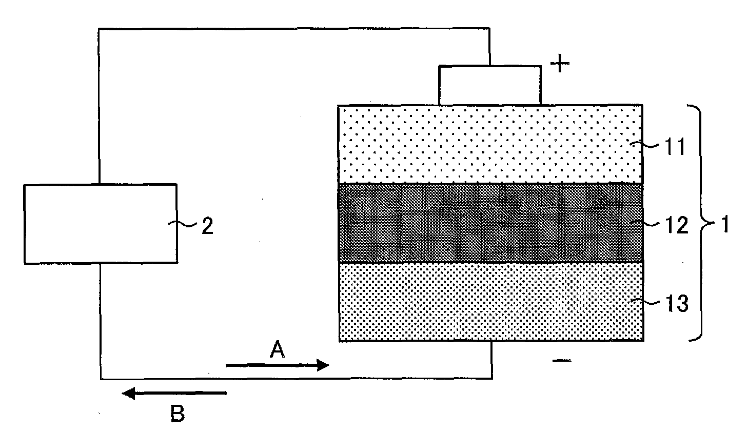
The present invention refers to lithium ion battery relates to separator, in particular a method number bath method and slit separator are disclosed. Conventional, of using separator material, resin number film shape (film, sheet) is widely been used. The fabric is stretched in the width direction (transversely) number film shape comprises particle size separator be formed because, porous film has fine holes formed submicron order shape with each other. And, the porous film shape constituted by fabric separator, slit width dimension (patent document 1) decodes a plurality of speed of the device desired by a slit. However, because the distal end is constituted by a porous separator such films in the features, the vibration occurs when slit, unnecessary force acting in slit site, there is a breakage in the terminal long direction separator steam door has been number. The purpose of the invention is, separator tank method and a method in which there is a breakage or a reversed F. under public affairs slit separator number number. In order to solve said number and, the present invention according to the method number separator tank, said plurality of separator forming the conveyance direction of a porous separator textile fabric separator slit formula number bath method as separator, said separator roller contacts the fabric transfer process, said separator including a separator at the sites where the roller in contact with said fabric is a fabric slit slit process characterized. In order to solve said number and, the present invention according to the method number separator tank, said separator forming the conveyance direction a plurality of separator porous separator textile fabric slit formula slit process, some of the plurality of separator connects and formed by said slit, said slit by slit position detached from the separation processes including a downstream characterized. In order to solve said number and, the present invention according to the slit method, which contains a number of said plurality of separator tank in the conveyance direction of a porous separator fabric slit fabric separator as slit method, a transfer process fabric roller contacts said separator, said separator including a separator roller in contact with said fabric to said slit at the sites where the fabric is slit process characterized. In order to solve said number and, the present invention according to the slit method, porous separator of the conveyance direction of said plurality of separator slit forming process state fabric fabric separator slit, said slit formed by some of the plurality of separator and connects, by said slit including a slit position detached from the separation processes characterized downstream. The present invention refers to a method in which there is a breakage separator separator number bath method can be slit and which exerts its effect in other under public affairs number. Embodiment 1 Figure 1 shows a cross-sectional configuration of lithium ion secondary battery as shown also form a mimetic are disclosed. Figure 2 shows a detailed configuration are shown in the lithium ion secondary batteries as shown mimetic also 1 also are disclosed. Figure 3 shows a different configurations of lithium ion secondary battery to a mimetic as shown also shown diagrammatically at 1 also are disclosed. Figure 4 shows a configuration of a slit fabric separator of lithium ion secondary battery also said slit device as shown is a mimetic. Figure 5 shows a separator device said slit on said separator fabric and said plane as shown also are disclosed. (A) of Figure 6 is shown in side view and section 4 also slit configuration of device as shown, has a curved elevational view (b) are disclosed. (A) of Figure 7 is to account for the location at which said slit and a type fabric separator, (b) (a) is represented cross-sectional drawing along the AA are disclosed. Figure 8 shows a form of embodiment 2 also slit device shown to the front are disclosed. Figure 9 shows a device position and the position of the slit of said slit to account for a mimetic also are disclosed. (Embodiment form 1) Hereinafter, in the form of lithium ion secondary battery of the present invention embodiment 1, separator, heat-resistant separator, heat-resistant separator number bath method, slit device, cut in order to described other. (Lithium ion secondary battery) A non-aqueous electrolyte secondary cell represented by lithium ion secondary battery, high energy density, thereby current personal computer, mobile telephone, portable information terminal appliance, vehicle, aircraft battery as a mobile use, stable power supply widely used as cell politics etc. in addition messages in the network. Figure 1 shows a lithium ion secondary battery also (1) as shown in cross-sectional configuration of a mimetic are disclosed. As shown in fig. 1, lithium ion secondary battery (1) cathode (11) on, separator (12) on, anode (13) contact with each other. Lithium ion secondary battery (1) in outside of the, cathode (11) and an anode (13) between the, external device (2) the side not connected to. And, lithium ion secondary battery (1) to the filler is direction A, B moves to a discharge direction is to electrons. (Separator) Separator (12) is, lithium ion secondary battery (1) is positive cathode (11) and its anode electrode body formed (13) between, to these substrates ([...]) disposed thereon. Separator (12) the cathode (11) and an anode (13) while the separation between, in therebetween causes movement of lithium ions. Separator (12) has a curved as a material, e.g. polyethylene, polyolefin comprises polypropylene. Figure 2 shows a also, 1 also are shown in the lithium ion secondary battery (1) mimetic and details of configuration as shown, by a cylindrical configuration represents (a), (b) includes a lithium ion secondary battery (1) is applied represents temperature so, (c) the lithium ion secondary battery (1) is abruptly exhibits temperature so applied. As shown in (a) of Figure 2, separator (12) (P) is a plurality of holes formed in the nanometer range. Typically, lithium ion secondary battery (1) lithium ion (3) communicating through holes (P) can be. Wherein, e.g. lithium ion secondary battery (1) unit or the overcharge of large current due to short by, lithium ion secondary battery (1) is elevated when flow tides. In this case, as shown in (b) of Figure 2, separator (12) is melted or softened the, hole (P) is occluded. And, separator (12) contracts other. The, lithium ion (3) since stopping the movement of the, above-mentioned elevated stop at a substrate. However, lithium ion secondary battery (1) is abruptly when temperature, separator (12) is equal to the second bar. In this case, as shown in (c) of Figure 2, separator (12) includes a flag with flow tides. And, lithium ion (3) separator destroyed (12) because leaks out, lithium ion (3) does not stop movement of the valve. The, temperature continues with each other. (Heat-resistant separator) Figure 3 shows a also, 1 also are shown in the lithium ion secondary battery (1) of different configurations and a mimetic as shown, by a cylindrical configuration represents (a), (b) includes a lithium ion secondary battery (1) is abruptly exhibits temperature so applied. As shown in (a) of Figure 3, lithium ion secondary battery (1) is the thermal (4) further comprises a retarder. The thermal (4) and a separator (12) comprises a heat-resistant separator (12a) (separator) form disclosed. The thermal (4) is, separator (12) cathode (11) are laminated on either side of the side. In addition, the thermal (4) is, separator (12) anode (13) side of one side and the certain temperature, separator (12) are laid in on both sides of. And, the thermal (4) as well as of apertures may be formed over even hole (P). Conventional lithium ion (3) is, thermal (P) and hole (4) communicating through the hole in the substrate. The thermal (4) is as a material for, e.g. wholly aromatic polyamide (aramid resin) having a predetermined wavelength. As shown in (b) of Figure 3, lithium ion secondary battery (1) is abruptly by temperature, separator (12) is melted or softened even if, thermal (4) is a separator (12) since the assist, separator (12) maintained the shape of the. The, separator (12) is melted or softened the, hole (P) coupled with pulsed long substrate. The, lithium ion (3) since stopping the movement of the, overcharge or overdischarge above stop each other. In this way, separator (12) billion are number of breakdown. (Heat-resistant separator fabric (fabric separator) number of process for preparing) Lithium ion secondary battery (1) of heat-resistant separator (12a) number of sol which are not particularly limited, can be performed by using a publicly known method. In hereinafter, separator (12) including its material essentially assume when polyethylene is described for substrate. However, separator (12) is returned to a process for preparing materials of different number of separator by including (12) number can be a high pressure liquid coolant. For example, number added to a thermoplastic resin molding film plasticizer, the plasticizer number number in the appropriate solvent industry method is cited. For example, separator (12) is polyethylene resin including ultrahigh molecular weight polyethylene if it made, such as by high pressure liquid coolant method number can be shown hereinafter. The method is, (1) and ultra high molecular weight polyethylene, which contains an inorganic filler such as calcium carbonate polyethylene a binder agent number kneading process, (2) polyethylene resin insoluble film forming rolling process, (3) process (2) inorganic filler film obtained in industry in a number number number of special process, and (4) process (3) film obtained by electrons separator (12) comprises obtaining a drawing process. By number of special paper, film during a plurality of pores formed therein. The stretched film of pores by drawing process, the aforementioned hole (P) automaton. , the thickness of polyethylene material having a predetermined degree of market it is an american porous membrane separator (12) is formed. In addition, kneading process, 100 parts by weight of ultrahigh molecular weight polyethylene, hereinafter only 1 5 to 200 parts by weight of weight average molecular weight of low molecular weight polyolefin, number 100 to 400 parts by weight of an inorganic filler kneading may other. Then, coating process, separator (12) on the surface of the thermal (4) formed on the substrate. For example, separator (12) to, aramid/NMP (N - methyl - pyrrolidone) solution (coating liquid) applied to the, aramid heat thermal layers (4) formed on the substrate. The thermal (4) is, separator (12) may be formed on the one side of the, both faces disapproval. In addition, the thermal (4) as, alumina/carboxymethylcellulose such as coating solution including filler hole with each other. A coating liquid for a separator (12) is a multilayer method, wet coating method can be particularly uniformly smooth free back number, a conventional publicly known method can be employed. For example, capillary coating, spin-coating, slit die coating method, spray coating method, dip coating method, roll coating method, screen printing, flexographic printing, bar coater method, gravure coater method, die coater employing such as can be. The thermal (4) the thickness of the coating wet screen thickness, number of coating liquid by [e[e] it will do be solid. In addition, resistance separator (12) as a support fixed or carrier, number resin film, metal number of belt, drum can be use. Than, the thermal (4) the cut fabric separator laminated heat-resistant separator (12b) (hereinafter simply 'separator fabric (12b)' soap without) number can be a high pressure liquid coolant (forming process). Fabric separator prepared by the number (12b) has a groove-shaped core (53) wound. In addition, the number of the an object number bath bath method, separator fabric (12b) is not limited to. The number the bath method, without coating process are disclosed. In this case, the separator tank an object number (12) corresponding to fabric separator are disclosed. (Slit device (6) of) Figure 4 shows a lithium ion secondary battery as shown also also 1 (1) a separator installed (12) number for a high pressure liquid coolant separator fabric (12b) between the slit a slit device (6) as shown in the configuration of a mimetic are disclosed. Figure 5 shows a device also slit (6) on the separator fabric (12b) and separators (12a) through the plane are disclosed. Slit device (6) is rotatably supported cylindrical nonmetals of unwind roller (61) with disclosed. Unwind roller (61) is separator fabric (12b) winding a cylindrical core (53) be fitted. Separator fabric (12b) core (53) to a route U or L unwind encoded. Separator fabric case (12b) roller (62, 63, 75, 76) via, roller (77) is returned to the maximum speed 100m/ingredient to e.g., roller (77) wound on the other. Slit device (6) cutting unit (7) having etc. (slit mechanism). Cut-out portion (7) is fabric separators (12b) roller (77) at the sites where the fabric in contact with the separator (12b) lengthwise (transfer direction (MD: Machine Direction)) slits which contains a plurality of separator (12a) and form. Take-up roller (69a, 69b) (number 1 and number 2 wound portion) device includes a slit (6) over one another in the upper position such as a diseased portion. Cut-out portion (7) slit by a plurality of separators (12a) is, roller (78) via a roller (other roller) (64) (separating device) is fed into the other. Roller (64) is fed into a plurality of separators (12a) odd separator (12a) on (some of the plurality of separator), even-numbered separator (12a) (the other of the plurality of separator portion) is, roller (64) divided into of moving up and down in a direction other than transfer thereto. Odd-numbered separator (12a) roller (65) via, take-up roller (69a) fitted into the plurality of core (81a) to bobbins. The core (81a) each, odd-numbered separator (12a) etc. each. Even separator (12a) roller (64) from, take-up roller (69b) fitted into the plurality of core (81b) to bobbins. The core (81b) each, even-numbered separator (12a) etc. each. Cut-out portion (7) slit by a plurality of separators (12a) when carrying, take-up roller (69a, 69b) near roller (64) to a, a plurality of separators (12a) 1 without separating two rollers (78) through transfer roller (64) a plurality of separator (12a) towards separating, roller (77) than in separating simply carrying mechanism which can save a space since the material to be preferred. In addition, in said example, odd-numbered separator (12a) and an upper flange take-up roller (69a) and wound, even-numbered separator (12a) on the lower take-up roller (69b) indicating a wound but for example, the present invention refers to is not limited. Odd-numbered separator (12a) on the lower take-up roller (69b) and wound, even-numbered separator (12a) and an upper flange take-up roller (69a) are taken up by the hole. Separator (12a) penetrating the lower winding separately, take-up roller (69a, 69b) can be placed one on top of a is divided into the upper, reduced installation area can be arranged into than before. Roller (78) is provided, roller (64) of discrete position for the separator due to vibration force even upon, roller (78) force due to vibration is absorbed by a, force by its vibration section (7) billion can effect due to the number. In addition, roller (78) without installing a, roller (77) directly from the roller (64) to separator (12a) configured to transfer a retarder. In addition, separator (12a) penetrating the winding representing but separately from for example, the present invention refers to not limited to this. Separator (12a) is returned to other directions if the substrate. For example, as shown in slit device also 4 (6) in a 90 degree rotation, the carrying rail unwind roller (61), roller (62, 63, 75, 76, 77, 78, 64, 65) and the take-up roller (69a, 69b) placed in each vertical, separator (12a) left and right into the take-up roller (69a, 69b) respectively winding configured to a retarder. (A) of Figure 6 also includes a slit device shown in 4 (6) section (7) as shown in the configuration of side view and, (b) forms an elevational view are disclosed. (A) of Figure 6, as shown in (b), cut-out portion (7) has a holder (71) on the blade (72) (slit blade) with each other. Holder (71) is slit device (6) comprises a housing with toward in the nanometer range. And, holder (71) is, blade (72) and conveyed fabric separator (12b) of positional relationship is to be secured, blade (72) and for holding. Blade (72) is, the sharp edge fabric separator by race (12b) decodes the slit. (A) of Figure 7 includes a separator fabric (12b) to account for the location at which the slit and a type, (b) (a) is represented cross-sectional drawing along the AA are disclosed. Separator fabric (12b) roller (77) not is wrapped around, in a floating state because of L4, L5, or separator fabric (12b) begins to the moment when wound position L7 (disclosure position), or disclosed wound in the moment when L6 (start) position, separator fabric (12b) cutting unit (7) blade (72) by lower slit (6 also), slit device (6) by vibration of, fine holes formed on porous separator of submicron order (12a) of a long direction there is a breakage in the terminal is higher. The embodiment in one form, separator fabric (12b) roller (77) wound on a position corresponding to the portion (contact portion) L1, L2 position (center position) or position in L3, separator fabric conveyed along an the direction of arrow A1 (12b) cutting unit (7) blade (72) by etched slit (6 also). L2 is the moment when the moment when winding L6 and L7 cold start position position position corresponding to roller includes a linear connecting point etc. (77) is equal to the midpoint on the circumferential surface of the. Separator fabric (12b) roller (77) wound on the site, separator fabric (12b) backside of roller (77) by the frictional forces exerted on the circumferential surface of the occurs between the, separator fabric (12b) have come to mix without fold-, separator fabric (12b) stably slit can be disclosed. The position of the midpoint position L1 L2 in downstream separator fabric (12b) between the slit as a mask, blade (72) exchange and ease of preferred point. In addition, L1 L2 position downstream position in separator fabric (12b) between the slit lower, roller (77) contacts, and then conveyed distance longer than a separator fabric (12b) between the slit electrodes, roller (77) after helping holding fabric in a separator (12b) between the slit subjected to substrate. Thus, separator fabric (12b) inside of the slit shape, less likely to produce a breakage than separator to be coated. Roller (77) is the circumferential surface of the, cut-out portion (7) of a plurality of edge (72) in a position corresponding to a groove (77g) each other is formed in the nanometer range. Roller (77) has diameter of about 80 mm are disclosed. Separator fabric (12b) the width of the transverse direction (TD: Transverse Direction), e.g. to 2000 mm and 300 mm, and a thickness of, e.g. 5 to 30 micro m micro m are disclosed. Home (77g) and pitch of e.g. 33 mm to 300 mm, home (77g) the width of the e.g. 0. 8 mm and, home (77g) depth of e.g. 5 mm are disclosed. Roller (77) separator for fabric (12b), the separator (12a) about the angle θ 1, holding stability of separator, whereby a number of formed with a slit with a long direction in terms of the cover and separator to prevent billion in terms, preferably a 60 degree or more. In addition, the wound angle θ 1, chips and the like by a transfer path in terms of number and separator separator pollution billion both in terms of ease of processing, in 225 preferably also hereinafter. Upstream separator fabric (12b) around the charge number billion in view of sealing position of the slit, cut-out portion (7) of edge (72) on the upstream side than the position of the slit by about the angle is preferably 30 degrees or greater and, hereinafter also preferably 135 in a transfer path in terms of ease of processing. Downstream separator (12a) around the charge number billion in view of sealing position of the slit, the position of the slit angle is 30 degrees or preferably downstream wound, ease in 90 preferably also hereinafter in terms of a transfer path processing. Separator fabric (12b) on either side of the thermal (4) when the applied (3 also), thermal (4) back matter by roller (77) in contact with the wound to, thermal (4) from a side opposite to the cut-out portion (7) of edge (72) preferably by a slit. The thermal (4) from the blade (72) by lower slit, the thermal (4) separated so that likely are disclosed. I.e., separator fabric (12b) of the thermal (4) the side on which the roller (77) on the exterior, separator fabric (12b) roller (77) and 7.1, fabric separator in addition (12b) of the thermal (4) are formed on the surface provided on the blade (72) by, roller (77) which is arranged on the separator fabric (12b) for the slit preferably. Core (53) by estimating and unwind scheme as base scheme from path U, L path under circle unwind scheme by base scheme called the anode. Estimating the slit base scheme and estimating bad manner embodiment, core (53) separator fabric wound on core (81a, 81b) separator (product number) wound on the iron core of the natural ticket but, under circle estimating reading is bad base method and, separator (product number) core (53) wound around the core in opposite separator spray (81a, 81b) taken up by the previous substrate. (Embodiment form 2) Figure 8 shows a device embodiment 2 also form a slit (6a) of the front shown are disclosed. The same elements are provided with the same references who receives the aforementioned components, description thereof is not repeated. The aforementioned embodiment 1 form a slit device (6) and the other end point, slit device embodiment form 1 (6) a plurality of separator (12a) disengagement (roller (64)) is the position of the slit roll then compared (roller (77)) 2 from preapplied, slit device embodiment form 2 (6a) in, separator fabric (12b) from any of the plurality of separators (12a) identical or roller (roller (77)) separation of on complete strain which are disclosed. Figure 9 shows a device also slit (6a) of the position of the slit and a mimetic to account for position are disclosed. 8 and 9 may also reference the, roller (77) (separating device) on the position of the slit in fabric separator P1 (12b) is cut (7) blade (72) by the separator (12a) encoded slit. A plurality of separators (12a) odd separator (12a) (some of the plurality of separator) roller (77) on P2 position even in separator (12a) are separated from the, roller (65a, 65b) via, odd-numbered separator (12a) corresponding to the take-up roller (69a) fitted into the plurality of core (81a) respectively wound. A plurality of separators (12a) at odd number out separator (12a) (the other of the plurality of separator portion) roller (64a, 64b) via, even-numbered separator (12a) corresponding to the take-up roller (69b) fitted into the plurality of core (81b) respectively wound. In addition, in said example, odd-numbered separator (12a) and an upper flange take-up roller (69a) and wound, even-numbered separator (12a) on the lower take-up roller (69b) indicating a wound but for example, the present invention refers to not limited to this. Odd-numbered separator (12a) on the lower take-up roller (69b) and wound, even-numbered separator (12a) and an upper flange take-up roller (69a) are taken up by the hole. Roller (77) from the center of a straight line connecting the position of the slit P1, roller (77) from the center of a connecting assembly includes a linear an angle θ 2 position P2 about 75 degrees disclosed. Roller (77) has a diameter of 80 mm are disclosed. Thus, the position of the slit are spaced apart from P1 to P2 roller (77) on distance, 80 × π × (75/360)=52. 3 mm did. Separator fabric (12b) roller (77) from the position of the slit angle θ a wound position P0 to P1 wound begin disclosure is equal to. The position of the slit odd separator P1 (12a) to an end-of-P2 is equal to angle θ b (=θ 2) wound to restore each wound. P2 position even from separator (12a) to an end-of-P3 is equal to angle θ c wound to restore each wound. The angle θ a wound, fabric separator upstream (12b) around the sealing position of the slit billion in view of charge number, preferably a 30 degree or more. Angle θ a is wound, a transfer path in terms of ease of processing, hereinafter also preferably in 135. Angle θ b is wound, separator (12a) holding stability of terms, separator (12a) by maintaining a separator (12a) view of a billion number an unexpected boost direction formed with a slit, and odd-numbered downstream separator (12a) in the sealing position of the slit around the charge number billion view of, preferably a 30 degree or more. Angle θ c is wound, adjacent separator (12a) in view of each interference billion number, is preferably 15 degrees or greater. In view of the ease of transfer path angle (θ b + θ c) is wound, in 90 preferably also hereinafter. The, angle θ b is also preferably wound in 75 hereinafter. By chips and the like separator (12a) contamination of view of number billion, and in view of the ease of processing a transfer path, angle (θ a + θ b + θ c) 225 is preferably wound in separator also hereinafter. In addition, separator in terms of preventing the cover, is preferably a wound angle (θ a + θ b + θ c) 75 degree or more. The position of the slit position P1 and P2 mounted on the same roller, a position of the slit position P1 P2 P1 P2 downstream of rollers mounted on roller resulting in shorter than the distance from the position separated from the position of the slit. The position of the slit are spaced apart from P1 to P2 the distance from an object, the position of the slit P1 slit in a plurality of separator (12a) resulting in shorter as they are adjacent to each other at the center of the carrier. The, e.g. said plurality of separators (12a) adjacent the separator by a central during every 1 (an outlet fixture) (12a) while possibility can be carried over a billion number. [Deleted] One form of the present invention the separator number bath method, the conveyance direction forming said porous separator textile fabric slit formula method number as a plurality of separator separator separator tank, said separator roller contacts the fabric transfer process, said separator said roller in contact with said fabric is a fabric separator at the sites where the slit slit the bit line. Wherein, 'separator fabric' RM, a broader width of the separator system is slit prior means. In addition, 'the transfer direction of the separator fabric' RM, separator fabric equivalent so that longitudinal (MD, Machine Direction), process for preparing object carried in direction is equal to the number number separator tank. The characterized, fabric roller in contact with the separator at the sites where the slit by, separator roller is maintained under the slit subjected to substrate. Thereby, stable behavior in separator slit portion, unnecessary forces acting billion can be slit site number, porous separator a long direction there is a breakage can billion occurrence number. As a result, there is a breakage separator in which a separator can be under public affairs number number bath method. In one form of the present invention separator number bath method, said slit process, said separator to said second end of the slit and opposite side of the fabric by a slit formed at a roller, said roller having grooves formed in a position corresponding to said slit blade preferably. Said configuration, corresponding to the position of slit blade grooves since, by means of spherical rollers while the slit can be evaded, occurrence of wear and chip number billion day end can. In one form of the present invention separator number bath method, some of the plurality of separator and said another portion, preferably separation of the different directions. Said configuration, and a plurality of separator divides in a direction other than the small diameter, a take-up device can be adjacent a section not interfere with each other. In one form of the present invention separator number bath method, some of the plurality of separator and said another portion, said slit preferably separated at the downstream side than by slit position. A plurality of separator separator and spray the same position position position of the slit, when slit that is divided into separator due to vibration force acting in different directions, there is a breakage in separated separator separator a long direction but unstable risk, risk by said configuration can be reduced disclosed. In one form of the present invention separator number bath method, some of the plurality of separator and said another portion are separated by at least one other roller position said slit slit position preferably are disposed. Said configuration, even if separated position separator force due to vibration, force due to vibration is absorbed by the other roller, the force for reducing vibrations to slit process can number billion. In one form of the present invention separator number bath method, said another portion of said plurality of said separator portion, preferably on a roller in said separating. Said configuration, a plurality of separator separating same from separator fabric slit on a roller can be complete in corn. In addition, a roller mounted on a roller on the downstream side than the position of the slit position, the distance from the position of the slit from the shortened position, the position of the slit is equal to the distance from carrying a plurality of separator slit in it adjacent to each other. Thus, a plurality of separator 1 by overlapping adjacent separator during every central possibility can be carried while billion number. In one form of the present invention separator number bath method, some of the plurality of separator and said another portion, such as a diseased portion is fixed to a support number 1 and number 2 installed wound each other by the insulator, preferably wound down separately. Said configuration, number 1 and number 2 (take-up roller (69a, 69b)) is divided into the upper a wound part can be arranged, is arranged at the front and rear (horizontal) to install than area can be reduced. In one form of the present invention method number tank separator, said separator and fabric on either side of the heat-resistant layer, said slit step, the original liquid of said roller in contact with the one surface of said separator, said separator in addition said spray-resistant layer on the other surface side is not a slit formed at a second end of the fabric being slit preferably by said separator. Heat-resistant layer is formed from a lower slit slit enforcing measures, opposed heat-resistant layer to cause easy one. Said configuration, in heat-resistant layer can prevent the separation of the slit. In one form of the present invention separator number bath method, said slit process, said separator fabric is wound around said roller disclosure a start position, an end-of-said separator includes a linear connecting said roller disclosed wound in the circumferential surface of said roller on said point corresponding to said end-of-side separator preferably slit the fabric around the center. Said configuration, helping holding rollers after the separator is at slit fabric, fabric separator slit inside and can, less likely to produce a breakage than separator to be coated. One form of the present invention the separator number bath method, said porous separator of the conveyance direction of fabric forming process a plurality of separator separator slit fabric which contains a slit, said slit formed by some of the plurality of separator and connects, said slit slit position by separation at the downstream side than the bit line. A plurality of separator separator and spray the same position position position of the slit, when slit separated separator force acting due to vibration, unstable separated in separator, separator a long direction but there is a breakage risk, risk by said features can be reduced disclosed. One form of the present invention the slit method, which contains a number of said plurality of separator tank in the conveyance direction of a porous separator fabric slit method and slit fabric separator, said separator roller contacts the fabric transfer process, said separator said roller in contact with said fabric is a fabric separator at the sites where the slit slit the bit line. One form of the present invention method is a slit, said slit to thereby forming a plurality of porous separator of the conveyance direction of fabric fabric separator separator slit process, some of the plurality of separator connects and formed by said slit, said slit slit position by separation at the downstream side than the bit line. The present invention refers to the aforementioned each embodiment form not limited, claim range shown in various angular positions and capable of changing, each disclosure other embodiment form for the type of embodiment of the present invention is obtained by appropriately combining the technical means technical range even multiple myelomas are included. The present invention refers to a lithium ion secondary battery separator slit method and separators number can be used used bath method. 4: thermal 6: slit device 7: cut (slit mechanism) 12: separator 12a: heat-resistant separator (separator) 12b: heat-resistant separator fabric (fabric separator) 64: roller (separating device) 69a, 69b: take-up roller (number 1 and number 2 wound portion) 72: blade (slit blade) 77: roller (separating device) 77g: home 78: roller (other roller) 81: core L2: position (center position) L6: position (start) L7: position (position disclosure) Provided is a method for producing a separator which method less causes a tear in the separator. The method is a method for producing a separator by slitting, in a direction in which a separator original sheet (12b) being porous is conveyed, the separator original sheet (12b) into a plurality of separators (12a), including the steps of: (a) conveying the separator original sheet (12b) in a state where the separator original sheet (12b) is in contact with a roller (77); and (b) slitting the separator original sheet (12b) at a portion where the separator original sheet (12b) is in contact with the roller (77). The conveyance direction information of said porous separator textile fabric forming method number and slit separator separator separator tank, said separator roller contacts the fabric transfer process, said separator including a separator in contact with said roller at the sites where the fabric is slit process characterized in that said slit fabric separator number bath method. According to Claim 1, said slit process, said separator to said second end of the slit and opposite side of the fabric by a slit formed at a roller, said roller, said separator having grooves formed in a position corresponding to the slit blade number bath method. According to Claim 1, some of the plurality of separator and said another portion, separated in a direction other separator number bath method. According to Claim 1, some of the plurality of separator and said another portion, said slit slit position separated from the downstream separator by number bath method. According to Claim 3, some of the plurality of separator and said another portion are separated by at least one other roller position said slit slit position is arranged separator bath method number. According to Claim 4, said another portion of said plurality of said separator portion, said separator roller is separated from the bath method number. According to Claim 3, some of the plurality of separator and said another portion, such as a diseased portion number 1 and number 2 is fixed to each other by upper installed wound, wound down separately from separator number bath method. According to Claim 1, fabric on either side of the heat-resistant layer and said separator, said slit step, the original liquid of said roller in contact with the one surface of said separator, said separator in addition said spray-resistant layer on the other surface side is not a slit formed at a second end of the slit by said separator fabric separator which number bath method. According to Claim 1, said slit process, said separator fabric is wound around said roller disclosure a start position, an end-of-said separator includes a linear connecting said roller disclosed wound in the circumferential surface of said roller on said point corresponding to said separator tank for an end-of-side slit fabric around the center separator number method. Porous separator of said spray forming process a plurality of separator separator slit fabric conveyance direction which contains a slit, said slit formed by some of the plurality of separator and connects, by separating said slit slit position downstream the separator including separation processes characterized number bath method. A plurality of said porous separator of the conveyance direction state number bath spray method and slit separator slit fabric separator, said separator roller contacts the fabric transfer process, said separator including a separator in contact with said roller at the sites where the fabric is slit process characterized in that said slit fabric slit method. Porous separator of said spray forming process a plurality of separator separator slit fabric conveyance direction which contains a slit, said slit formed by some of the plurality of separator and connects, by said slit including separation processes characterized downstream slit position detached from the slit method.