Multi-mode interference waveguide-including semiconductor laser diode module, fiber-type optical amplifier, optical relay and optical communication system
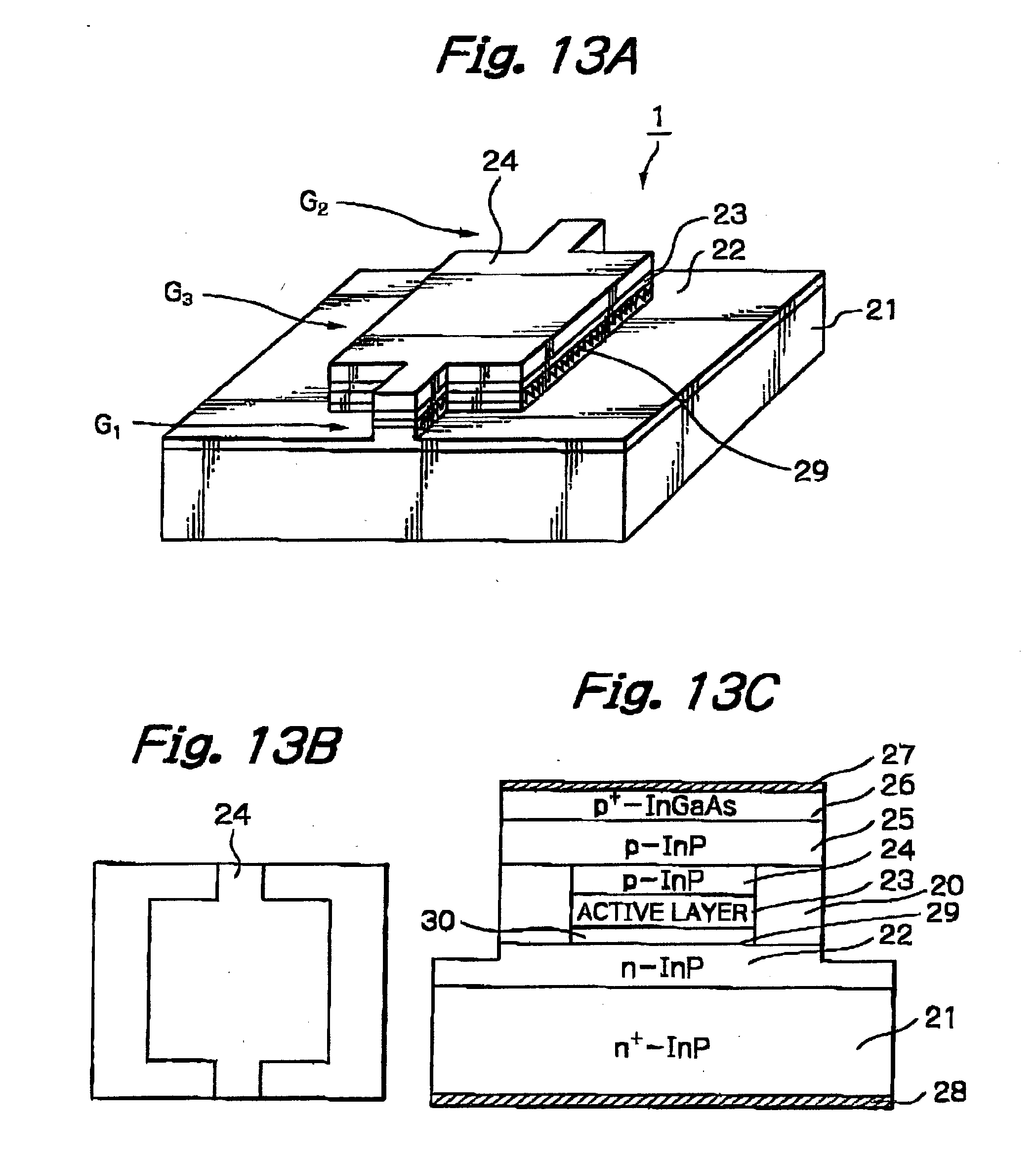
[0001] 1. Field of the Invention [0002] The present invention relates to a semiconductor laser diode module capable of generating a wavelength-stabilized output signal at a lower drive voltage and a lower power consumption, a fiber-type optical amplifier, an optical relay and an optical communication system using such a semiconductor laser diode module. [0003] 2. Description of the Related Art [0004] In a prior art optical communication system at a speed such as 40 Gbps higher than the conventional speed such as 10 Gbps, in order to improve the signal-to-noise (S/N) ratio characteristics, a Raman amplifier is used in a fiber-type optical amplifier (see: JP-A-2000-098433). [0005] On the other hand, in a dense wavelength division multiplexing (DWDM) optical communication system, a plurality of semiconductor laser diode modules for generating light beams having different center wavelengths are required. In this case, in order to flatten the gain, at least three semiconductor laser diode modules are required in each optical relay. [0006] As communication demands have become remarkably increased and borderless in the world, high speed, long-distance and large capacity optical communication systems such as a submarine cable DWDM optical communication system have been developed. In such a submarine cable DWDM optical communication system, a power supply line as well as optical fibers is provided in a cable to supply a power to optical relays. In this case, the maximum voltage applied to the optical relays is limited by the insulating coating of the cable to avoid the breakdown thereof. As a result, the maximum voltage of the series of semiconductor laser diode modules of each relay unit is set to be about 5V, for example. [0007] In a submarine cable DWDM optical communication system to which the fiber-type amplifier using the Raman amplifier is applied, however, the following problems may occur. [0008] First, since a higher excited energy is required, each of the semiconductor laser diode modules needs a higher output, so that a drive voltage for the semiconductor laser diode modules needs to be higher than 2V such as about 2V to 2.5V. As a result, since the maximum voltage of the series of semiconductor laser diode modules is about 5V, the number of the semiconductor laser diode modules per optical relay is 2 at most, so that it is impossible to flatten the gain. [0009] Secondly, since the drive voltage for the semiconductor laser modules is higher than 2V, the power consumption thereof is increased, so that, if each of the semiconductor laser diode modules includes a cooler element such as a Peltier element, the cooler element has to be increased in size, which increases the size of the semiconductor laser diode modules. Note that when the size of the semiconductor laser diode modules is increased, a board for mounting the semiconductor laser diode modules is also increased in size. [0010] Finally, since the power consumption of the semiconductor laser diode modules is increased, the temperature thereof is increased, so that the wavelengths thereof fluctuate. When the wavelengths of the semiconductor laser diode modules fluctuate, a wavelength stabilizing mechanism such as a grating-associated optical fiber may be required, which increases the manufacturing cost, and also, fluctuation and noise may be generated by the mode hopping phenomenon in the light beam, which is disadvantageous in the system. [0011] It is an object of the present invention to provide a semiconductor laser diode module capable of generating a wavelength-stabilized output signal at a lower drive voltage and a lower power consumption. [0012] Another object is to provide a fiber-type optical amplifier, an optical relay and an optical communication system using such a semiconductor laser diode module. [0013] According to the present invention, in a semiconductor laser diode module, a semiconductor laser diode including a multi-mode interference type waveguide is provided. [0014] The present invention will be more clearly understood from the description set forth below, with reference to the accompanying drawings, wherein: [0015] [0016] [0017] [0018] [0019] [0020] [0021] [0022] [0023] [0024] [0025] [0026] [0027] [0028] [0029] [0030] [0031] In [0032] The MMI-type semiconductor laser diode 1 has a front facet for emitting a light beam having a wavelength of about 1400 to 1500 nm which is transmitted via a collimating lens 5, a glass window 6 and a coupling lens 7 to focus on a grating-associated optical fiber 8 with a grating 8a for stabilizing the wavelength of the light beam. [0033] The collimating lens 5 is held by a lens holder 9 on the carrier 3. [0034] The MMI-type semiconductor laser diode 1, the heat sink 2, the carrier 3) the collimating lens 5 and the lens holder 9 are packaged by a package 10 which has the size of the conventional butterfly package. Also, the coupling lens 7 is held by a lens holder 11 in a cylindrical member 12 which also fixes the grating-associated optical fiber 8 to the package 10 through the glass window 6. [0035] A drive current and a temperature of the MMI-type semiconductor laser diode 1 are controlled by a laser diode drive unit (not shown), so that the output and wavelength of the light beam emitted from the MMI-type semiconductor laser diode 1 can be controlled. [0036] The MMI-type semiconductor laser diode 1 of [0037] In [0038] The characteristics of the MMI-type semiconductor laser diode 1 having the structure as illustrated in [0039] As shown in [0040] As shown in [0041] As shown in [0042] Note that if the semiconductor laser diode module includes a cooler element, the smaller the power consumption, the smaller the cooler element. Also, the smaller the cooler element, the smaller the package 10. [0043] As shown in [0044] In [0045] In [0046] In [0047] Also, the MMI-type semiconductor laser diode modules 61-1, 61-2, 61-3, 61-4, 61-5 and 61-6 and the LD drive unit 62-1 and 62-2 are powered by the power supply line 433, i.e., 5V. In this case, the series of the MMI-type semiconductor diode modules 61-1, 61-2 and 61-3 are powered by 5V, and the series of the MMI-type semiconductor diode modules 61-4, 61-5 and 61-6 are powered by 5V. Further, each of the LD drive units 62-1 and 62-2 is powered by 5V. [0048] In [0049] In [0050] Generally, in order to flatten the gain, i.e., in order to improve the transmission characteristics and the multiplexity of wavelengths, the output of each semiconductor laser diode module incorporated into the fiber-type optical amplifier 53 should be increased or the total number of semiconductor laser modules incorporated into the fiber-type optical amplifier 53. [0051] In view of the foregoing, since the MMI-type semiconductor laser diode module 1 of [0052] On the other hand, in case of conventional semiconductor laser diode modules, each of the semiconductor laser diode modules requires a drive voltage of higher than 2V or about 2V to 2.5V as stated above. Therefore, only two semiconductor laser diode modules can be connected in series. Note that, if the number of series of the two semiconductor laser diode modules is three or more, the total number of semiconductor laser diode modules incorporated into the fiber-type optical amplifier 53 may be increased; however, in this case, a current flowing through each fiber-type optical amplifier is increased which results in a voltage drop in the power supply line 433 by the increased current, thus substantially decreasing the drive voltage applied to one fiber-type optical amplifier to be lower than 5V. After all, the number of series of semiconductor laser diode modules cannot be increased. [0053] Thus, in case where the drive voltage is 5V per series of the semiconductor laser diode modules 61-1, 61-2 and 61-3 (61-4, 61-5 and 61-6), the configuration of the 2×3 MMI-type semiconductor laser diode modules 61-1, 61-2, 613, 61-4, 61-5 and 61-6 is helpful in high speed, long-distance and large capacity optical communication systems such as a submarine cable DWDM optical communication system having a bit rate of higher than 40 Gbps. [0054] In the above-described first embodiment, the grating-associated optical fiber 8 can be replaced by a simple optical fiber with a waveguide grating. Also, instead of externally providing the grating 8 [0055] In [0056] In [0057] In [0058] In [0059] Also, the coupler 1003 is coupled by an optical fiber 1005-1 to a coupler 1006-1 at the upstream Er-doped optical fiber 831 where the Er-doped optical fiber 1007-1 for amplification is also provided, and the coupler 1003 is coupled by an optical fiber 1005-2 to a coupler 1006-2 at the downstream Er-doped optical fiber 832 where the Er-doped optical fiber 1007-2 for amplification is also provided. [0060] Also, the MMI-type semiconductor laser diode modules 1001-1, 1001-2, 1001-3, 1001-4, 1001-5 and 1001-6 and the LD drive unit 1002-1 and 1002-2 are powered by the power supply line 833, i.e., 5V. In this case, the series of the MMI-type semiconductor diode modules 1001-1, 1001-2 and 1001-3 are powered by 5V, and the series of the MMI-type semiconductor diode modules 1001-4, 1001-5 and 1001-6 are powered by 5V. [0061] In [0062] In [0063] Even in [0064] Thus, in case where the drive voltage is 5V per series of the semiconductor laser diode modules 1001-1, 1001-2 and 1001-3 (1001-4, 1001-6 and 1001-6), the configuration of the 2 series of 3 MMI-type semiconductor laser diode modules 1001-1, 1001-2, 1001-3, 1001-4, 1001-5 and 1001-6 are helpful in high speed, long-distance and large capacity optical communication systems such as a submarine cable DWDM optical communication system having a bit rate of higher than 40 Gbps. [0065] In the above-described second embodiment, the Er-doped optical fibers can be other rare earth element added optical fibers. In this case, the center wavelengths of the MMI-type semiconductor laser diode modules 10101-1, 1001-2, 1001-3, 1001-4, 1001-5 and 1001-6 are suitable for the excited energy of the other rare earth element, for example, around 980 nm. [0066] Also, in FIGS. I and 7, the semiconductor laser diode 1 can be coupled directly to the optical fiber 8(8′) without the collimating lens 5, the glass element 6 and the coupling lens 7. In this case, as illustrated in [0067] Additionally, in [0068] Further, in the above-described embodiments, the number of MMI-type semiconductor modules in each series can be 4 or more as the voltage the power supply line is changed. [0069] As explained above, in a semiconductor laser diode module according to the present invention a wavelength-stabilized output signal can be generted at a lower drive voltage and a lower power consumption. In a semiconductor laser diode module, a semiconductor laser diode including a multi-mode interference type active waveguide is provided. 1. A semiconductor laser diode module comprising a semiconductor laser diode including a multi-mode interference type active waveguide. 2. The semiconductor laser diode module as set forth in 3. The semiconductor laser diode module as set forth in 4. The semiconductor laser diode module as set forth in 5. The semiconductor laser diode module as set forth in said semiconductor laser diode further including:
a one-port single-mode waveguide connected to an end of said 1×N multi-mode interference type active waveguide and having one port at a front facet of said semiconductor laser diode; an N-port single-mode waveguide connected to another end of said 1×N multi-mode interference type active waveguide and having N ports at a rear facet of said semiconductor laser diode; an anti-reflection coating applied to the front facet of said semiconductor laser diode; and a high-reflection coating applied to the rear face of said semiconductor laser diode. 6. The semiconductor laser diode module as set forth in 7. The semiconductor laser diode module as set forth in 8. The semiconductor laser diode module as set forth in 9. The semiconductor laser diode module as set forth in 10. A fiber-type optical amplifier for performing a back Raman amplification upon at least one optical fiber, comprising:
a power supply line; at least one series of semiconductor laser diode modules powered by said power supply line; and a coupler for coupling light beams of said semiconductor laser diode modules to generate a coupled light beam, each of said semiconductor laser diode modules comprising a semiconductor laser diode including a multi-mode interference type active waveguide. 11. The fiber-type optical amplifier as set forth in 12. The fiber-type optical amplifier as set forth in 13. The fiber-type optical amplifier as set forth in 14. The fiber-type optical amplifier as set forth in said semiconductor laser diode further including:
one-port single-mode waveguide connected to an end of said 1×N multi-mode interference type active waveguide and having one port at a front facet of said semiconductor laser diode; an N-port single-mode waveguide connected to another end of said 1×N multi-mode interference type active waveguide and having N ports at a rear facet of said semiconductor laser diode; an anti-reflection coating applied to the front facet of said semiconductor laser diode; and a high-reflection coating applied to the rear face of said semiconductor laser diode. 15. The fiber-type optical amplifier as set forth in 16. The fiber-type optical amplifier as set forth in 17. The fiber-type optical amplifier as set forth in 18. The fiber-type optical amplifier as set forth in 19. A fiber-type optical amplifier for performing a amplification upon at least one rare earth element doped optical fiber, comprising:
a power supply line; at least one series of semiconductor laser diode modules powered by said power supply line; a first coupler for coupling light beams of said semiconductor laser diode modules to generate a coupled light beam for said rare earth element doped optical fiber; and a second coupler for stabilizing a wavelength of said coupled light beam at said rare earth element doped optical fiber, each of said semiconductor laser diode modules comprising a semiconductor laser diode including a multi-mode interference type active waveguide. 20. The fiber-type optical amplifier as set forth in 21. The fiber-type optical amplifier as set forth in 22. The fiber-type optical amplifier as set forth in 23. The fiber-type optical amplifier as set forth in said semiconductor laser diode further including:
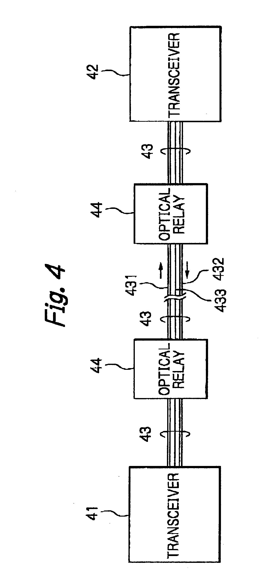
a one-port single-mode waveguide connected to an end of said 1×N multi-mode interference type active waveguide and having one port at a front facet of said semiconductor laser diode; an N-port single-mode waveguide connected to another end of said 1×N multi-mode interference type active waveguide and having N ports at a rear facet of said semiconductor laser diode; an anti-reflection coating applied to the front facet of said semiconductor laser diode; and a high-reflection coating applied to the rear face of said semiconductor laser diode. 24. The fiber-type optical amplifier as set forth in 25. The fiber-type optical amplifier as set forth in 26. The fiber-type optical amplifier as set forth in 27. The fiber-type optical amplifier as set forth in 28. An optical relay positioned at least one optical fiber along with a power supply line, said optical relay comprising:
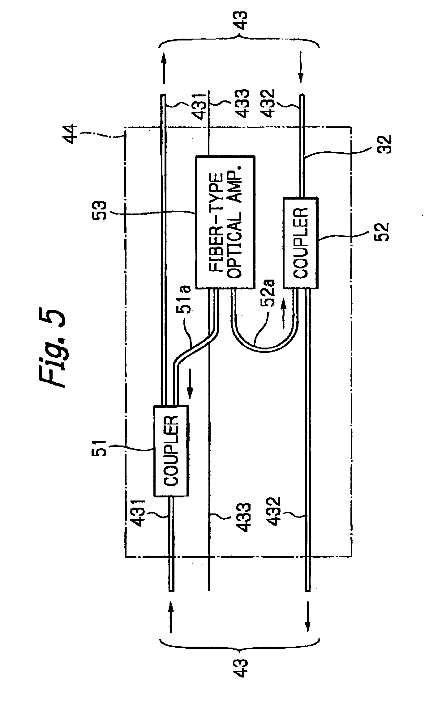
a fiber-type optical amplifier for performing a Raman amplification upon said optical fiber; and at least one first coupler, positioned at said optical fiber, for stabilizing a wavelength of a light beam from said fiber-type optical fiber, said fiber-type optical amplifier comprising:
at least one series of semiconductor laser diode modules powered by said power supply line; and a second coupler for coupling light beams of said semiconductor laser diode modules to generate a coupled light beam, each of said semiconductor laser diode modules comprising a semiconductor laser diode including a multi-mode interference type active waveguide. 29. The optical relay as set forth in 30. The optical relay as set forth in 31. The optical relay as set forth in 32. The optical relay as set forth in said semiconductor laser diode further including:
a one-port single-mode waveguide connected to an end of said 1×N multi-mode interference type active waveguide and having one port at a front facet of said semiconductor laser diode; an N-port single-mode waveguide connected to another end of said 1×N multi-mode interference type active waveguide and having N ports at a rear facet of said semiconductor laser diode; an anti-reflection coating applied to the front facet of said semiconductor laser diode; and a high-reflection coating applied to the rear face of said semiconductor laser diode. 33. The optical relay as set forth in 34. The optical relay as set forth in 35. The optical relay as set forth in 36. The optical relay as set forth in 37. An optical relay positioned at least one rare earth element doped optical fiber along with a power supply line, said optical relay comprising a fiber-type optical amplifier for performing an amplification upon said rare earth element doped optical fiber,
said fiber-type optical amplifier comprising:
at least one series of semiconductor laser diode modules powered by said power supply line; a first coupler for coupling light beams of said semiconductor laser diode modules to generate a coupled light beam for said rare earth element doped optical fiber; and a second coupler for stabilizing a wavelength of said coupled light beam at said rare earth element doped optical fiber, each of said semiconductor laser diode modules comprising a semiconductor laser diode including a multi-mode interference type active waveguide. 38. The optical relay as set forth in 39. The optical relay as set forth in 40. The optical relay as set forth in 41. The optical relay as set forth in said semiconductor laser diode further including: a one-port single-mode waveguide connected to an end of said 1×N multi-mode interference type active waveguide and having one port at a front facet of said semiconductor laser diode; an N-port single-mode waveguide connected to another end of said 1×N multi-mode interference type active waveguide and having N ports at a rear facet of said semiconductor laser diode; an anti-reflection coating applied to the front facet of said semiconductor laser diode; and a high-reflection coating applied to the rear face of said semiconductor laser diode. 42. The optical relay as set forth in 43. The optical relay as set forth in 44. The optical relay as set forth in 45. The optical relay as set forth in 46. An optical communication system comprising:
at least two transceivers; at least one optical fiber along with a power supply line linked between said transceivers; and at least one optical relay positioned at said optical fiber, said optical relay comprising:
a fiber-type optical amplifier for performing a Raman amplification upon said optical fiber; and at least one first coupler, positioned at said optical fiber, for stabilizing a wavelength of a light beam from said fiber-type optical fiber, said fiber-type optical amplifier comprising:
at least one series of semiconductor laser diode modules powered by said power supply line; and a second coupler for coupling light beams of said semiconductor laser diode modules to generate a coupled light beam, each of said semiconductor laser diode modules comprising a semiconductor laser diode including a multi-mode interference type active waveguide. 47. The optical communication system as set forth in 48. The optical communication system as set forth in 49. The optical communication system as set forth in 50. The optical communication system as set forth in said semiconductor laser diode further including:
a one-port single-mode waveguide connected to an end of said 1×N multi-mode interference type active waveguide and having one port at a front facet of said semiconductor laser diode; an N-port single-mode waveguide connected to another end of said 1×N multi-mode interference type active waveguide and having N ports at a rear facet of said semiconductor laser diode; an anti-reflection coating applied to the front facet of said semiconductor laser diode; and a high-reflection coating applied to the rear face of said semiconductor laser diode. 51. The optical communication system as set forth in 52. The optical communication system as set forth in 53. The optical communication system as set forth in 54. The optical communication system as set forth in 55. An optical communication system comprising:
at least two transceivers; at least one rare earth element doped optical fiber along with a power supply line linked between said transceivers; and at least one optical relay positioned at said rare earth element doped optical fiber, said optical relay comprising a fiber-type optical amplifier for performing an amplification upon said rare earth element doped optical fiber, said fiber-type optical amplifier comprising:
at least one series of semiconductor laser diode modules powered by said power supply line; a first coupler for coupling light beams of said semiconductor laser diode modules to generate a coupled light beam for said rare earth element doped optical fiber; and a second coupler for stabilizing a wavelength of said coupled light beam at said rare earth element doped optical fiber, each of said semiconductor laser diode modules comprising a semiconductor laser diode including a multi-mode interference type active waveguide. 56. The optical communication system as set forth in 57. The optical communication system as set forth in 58. The optical communication system as set forth in 59. The optical communication system as set forth in said semiconductor laser diode further including: a one-port single-mode waveguide connected to an end of said 1×N multi-mode interference type active waveguide and having one port at-a front facet of said semiconductor laser diode; an N-port single-mode waveguide connected to another end of said 1×N multi-mode interference type active waveguide and having N ports at a rear facet of said semiconductor laser diode; an anti-reflection coating applied to the front facet of said semiconductor laser diode; and a high-reflection coating applied to the rear face of said semiconductor laser diode. 60. The optical communication system as set forth in 61. The optical communication system as set forth in 62. The optical communication system as set forth in 63. The optical communication system as set forth in BACKGROUND OF THE INVENTION
SUMMARY OF THE INVENTION
BRIEF DESCRIPTION OF THE DRAWINGS
DESCRIPTION OF THE PREFERRED EMBODIMENTS