METHOD AND DEVICE FOR SHAPING OF COMPOSITE MATERIAL
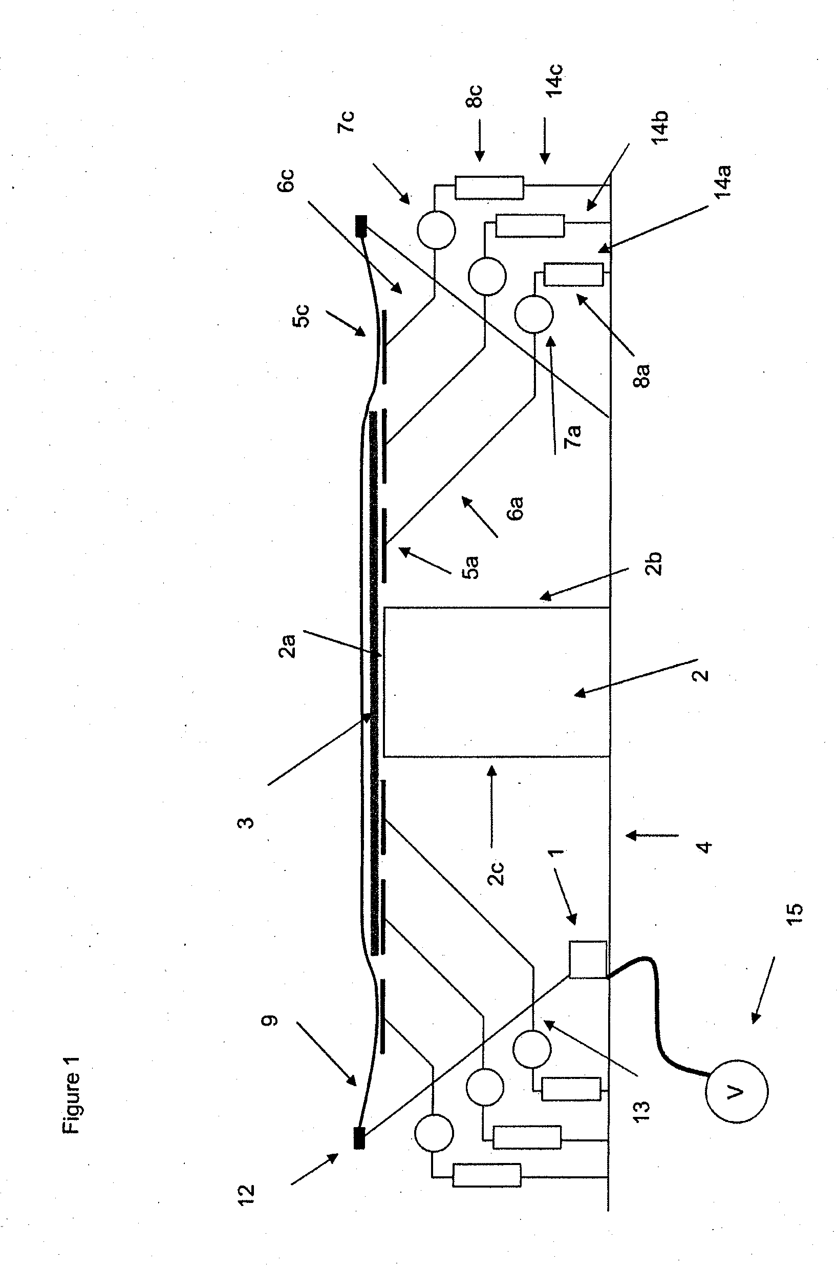
This application is a divisional application of co-pending U.S. patent application Ser. No. 12/248,351 filed 9 Oct. 2008 and claims priority to European patent application 07118136.9 filed 9 Oct. 2007. The present invention relates to a method and a device for shaping of composite materials e.g. thermoforming. Shaping of composite materials, such as pre-preg (layers of fibre material previously impregnated with resin), into details is today commonly performed by thermoforming. In thermoforming, a blank of composite material is placed on a forming tool so that a part of the composite material protrudes over the edge of the tool. The tool and the composite material are covered with a vacuum foil, such as a rubber sheet which is sealed air-tight around the tool. The arrangement is heated and the air under the vacuum foil is sucked out. Due to the increased temperature the composite material softens and is shaped over the forming tool by the force exerted by the vacuum foil exerted on the surface of the protruding part of the blank. The shaped article is thereafter placed in its green state in a curing oven for curing. Examples of related technology are presented in the documents EP1136236 A1, EP1609584 A1 and US 4548859 A1. When using the aforementioned method for shaping of complex composite articles, such as elongated C-shaped beams with longitudinal flanges, a common problem is that the material does not closely follow the contour of the forming tool as the material forms over tool. That is, the radius of the material that is bent over the edge of the tool becomes larger than the radius of the edge of the forming tool, the so called Mickey-mouse effect. This effect is comes due to the fact that the pressure from the vacuum foil is too low at the beginning of the forming process. The problem is even larger for heavy blanks which tend to self form over the tool due to their own weight at the beginning of the forming process. A further problem is that creases may arise in the articles, due to friction between fibre layers in the blank as the layers slide on each other during forming of the blank. In the case of shaping composite materials which comprise thermo-particles for increased impact strength, the tendency of creasing is even greater since the thermo-particles further increases the friction between the layers. Previous attempts for solving the above mentioned problems have included manual lay-up and forming over the tool. The use of manual labour for laying-up and forming the material over the tool is time consuming and involves high costs. Another known method for solving the aforementioned problems is to support the composite blank with a release sheet during forming. The disadvantage of this solution is that further forming of the article cannot be done, and that the release-sheet itself can be an incitement for the creation of creases in the composite. It is an object of the present invention to provide an improved shaping of composite materials into complex forms. This is achieved by a method being defined in the introduction. It is also an object of the present invention to provide a device for shaping a composite article. This is achieved by a device being defined in the introduction. The invention relates to a method of shaping an article of composite material, such as a beam for aircraft assemblies or the like. The method comprise the steps of arranging a blank of composite material on the top surface of a forming tool, a portion of the blank being arranged to protrude outside the top surface of the tool and supporting the protruding portion with at least one support means in contact with the underside of the protruding portion of the blank; arranging an air-tight foil over the arrangement; forcing the air-tight foil towards the blank; lowering the support means until the blank is shaped over the tool; stopping and/or removing the support means. Thereby a blank of composite material can be accurately shaped over a forming tool into an article of predetermined shape. The shape of the resulting article closely corresponds to the form and profile of the tool. The method is fast, simple and cost-effective and requires little manual labour. The protruding portion of the blank may be supported by several support means successively arranged in a direction outwards from the tool. Whereby the movement of the blank in relation to the tool in a direction outwards from the tool is allowed to be made in smaller steps and the forming against the tool is easier to control. The protruding portion of the blank may be supported by several support means successively arranged alongside the tool. The presence of a plurality of support means allows for forming of complicated shapes, in particular when there are support means arranged both successively in a direction outwards from the tool and support means arranged alongside the tool. The support means may be lowered in a predetermined order. Thereby is achieved that the shaping is performed in a controlled and efficient manner, thus achieving optimized shaping of the blank over the tool with regard to the contour of the tool and form and properties of the composite blank. The support means may be lowered in a predetermined order in a direction outwards from the tool, so that the blank very closely follows the contour of the forming tool during shaping and that the bending radius of the composite blank over the edge of the forming tool is minimized. The support means may also be lowered in a predetermined order alongside the tool. Thereby is achieved that the shaping of the blank can be initiated at a predetermined point alongside the tool. This enables shaping of the blank over a contoured tool. It also enables shaping of a blank with a varying cross-section over the tool. Consequently, blanks can be formed over the tool into articles with complex forms A first support means arranged next to the tool may be lowered when the force from the air-tight foil acting on said support means is higher than a pre-determined value. Whereby, the shaping operation can be controlled to initiate when the forming pressure is high enough to ensure that the blank is shaped closely over the edge of the tool, thus preventing self-forming of the blank; excessive radiuses at the bends; and the forming of creases in the shaped article. At least one successive support means, arranged adjacent to said first support means may be lowered when the force acting on said successive support means is higher than a pre-defined value and the force acting on the preceding support mean is reduced below a pre-defined value, so that the forming operation proceeds in a controlled manner assuring that the composite blank accurately shapes over the forming tool. The invention also relates to a device for shaping an article of composite material, such as a beam for aircraft assemblies or the like, the device comprises; a forming tool comprising a top surface and side surface for shaping at least one blank of composite material into an article having a predetermined profile; and an air-tight foil characterized in that the device comprises at least one support means arranged to be in supporting contact with the underside of the protruding part of the blank, thereby a device for shaping articles of composite material is achieved. The device enables accurate shaping of composite blanks over the forming tool into articles having a predetermined shape. The device is fast, reliable and enables automated production of shaped composite articles. Several support means may be successively arranged in a direction outwards from the tool. Whereby is achieved that the blank very closely follows the contour of the forming tool during shaping and that the bending radius of the composite blank over the edge of the tool is minimized. Several support means may be arranged alongside the tool. Thereby is achieved that shaping of the blank can be initiated at a predetermined point alongside the tool. This enables shaping of the blank over a contoured tool. It also enables shaping of a blank with a varying cross-section over the tool. Consequently, blanks can be formed over the tool into articles with complex forms Each support means may comprise raising/lowering means and is preferably arranged on an arm, thus forming a supporting arrangement so that a flexible controlled movement of the support, enabling the support means to be raised and/or lowered in a predetermined order is obtained. The device 1 according to the invention for shaping an article of composite material comprises a container 21 including a base 4, which is surrounded by an inclined wall 13. The base 4 supports a heatable forming tool 2 having a top surface 2 With the expression “composite material” is here intended a reinforcing material impregnated with a matrix material. The reinforcing material could for example be fibre, such as carbon fibre, glass fibre, aramide fibre or combinations thereof. The matrix material could be any plastic resin, for example a thermosetting plastic resin, such as epoxy. With the expression “air-tight foil” is here intended an air-tight, flexible foil which is strong enough to form the blank over the tool by the force of an over- or under-pressure acting on the foil. For example, the air-tight foil could be a vacuum foil, such is as a rubber foil, or a rubber sheet. As described in The air-tight foil 9, for example a rubber sheet, is arranged to be connected air-tight to the top of the surrounding inclined wall 13 by a seal 12. A vacuum port 10 allows air to be drawn from the device 1 by a vacuum pump 15. The device 1 further comprises pressure- or load sensors (not shown). The sensors could be arranged in the supporting arrangements 14 The support arrangements 14 Each of the support arrangements 14 Alternatively, each of the support arrangements 14 Alternatively, several lines A, B, C, D, etc may successively be arranged parallel to the tool 2 in a direction outwards from the tool 2. Each line comprises either one support arrangement 14 As described in An air-tight foil 9 is arranged over the top of the device 1 and sealed air-tight with a vacuum seal 12 to the top of the device 1. A vacuum pump 15 is connected to the vacuum port 10. The device 1 is heated to a temperature by which the composite material softens. The temperature could be in the range of 40-100° C. The vacuum pump 15 is started. The vacuum pump 15 draws vacuum underneath the air-tight foil 9, thus creating an under-pressure under the air-tight foil 9, the under-pressure could be down to −100 kPa. The under-pressure forces the air-tight foil 9 down, thus forcing the blank 3 towards the surface of tool 2 and also forces the protruding portion of the blank 3 towards the supporting arrangements 14 As the air-tight foil 9 forces the blank 3 downwards, the blank exerts a force on the support means 5 When the force from the air-tight foil 9 acting on the composite blank 3 has reached a pre-determined value, at which accurate forming of the composite blank 3 over the tool 2 is ensured, the first support means 5 When the support means 5 Several flat elongated support means 5 Alternatively, several flat elongated support means 5 The force acting on the blank 2 may be measured in the support arrangements 14 Alternatively, the support means 5 When the support means 5 Finally, the shaped article is removed from the tool 2 and transported to a curing oven e.g. autoclave where the article is cured. Although particular embodiments have been disclosed herein in detail, this has been done for purposes of illustration only, and is not intended to be limiting with respect to the appended claims. The disclosed embodiments can also be combined. In particular, it is contemplated by the inventors that various substitutions, alterations, and modifications may be made to the invention without departing from the spirit and the scope of the invention as defined by the claims. For instance various shaping surfaces could be provided in the tool, thus making it possible to shape various types of articles e.g. C-shaped beams or hat-shaped beams. The forcing of the vacuum foil towards the blank could be performed by exerting an over-pressure on the vaccum foil for example by using an autoclave or pressure chamber. Different methods for heating the device could be used e.g. hot air, hot gases or hot fluids or electrical heating. Different means for lowering the support means could be included in the device. The support means could be arranged to pivot towards the tool, the support means could be arranged to protrude from the forming tool or from the base of the device. A device for shaping of an article of composite material. The device includes a tool including a top surface and side surface for shaping at least one blank of composite material into an article having a predetermined profile; and a air-tight foil. The device further includes at least one support arranged to be in supporting contact with the underside of the protruding part of the blank. 1-8. (canceled) 9. A device for shaping an article of composite material, the device comprising:
a forming tool comprising a top surface and side surface for shaping at least one blank of composite material into an article having a predetermined profile; a air-tight foil; at least one support arranged to be in supporting contact with an underside of a protruding part of the blank. 10. The device according to 11. The device according to 12. The device according to 13. The device according to CROSS-REFERENCE TO RELATED APPLICATIONS
FIELD OF THE INVENTION
BACKGROUND OF THE INVENTION
SUMMARY OF THE INVENTION
BRIEF DESCRIPTION OF THE DRAWINGS
DETAILED DESCRIPTION OF THE PREFERRED EMBODIMENTS