ROBOT POWER SOURCE CHARGING STATION
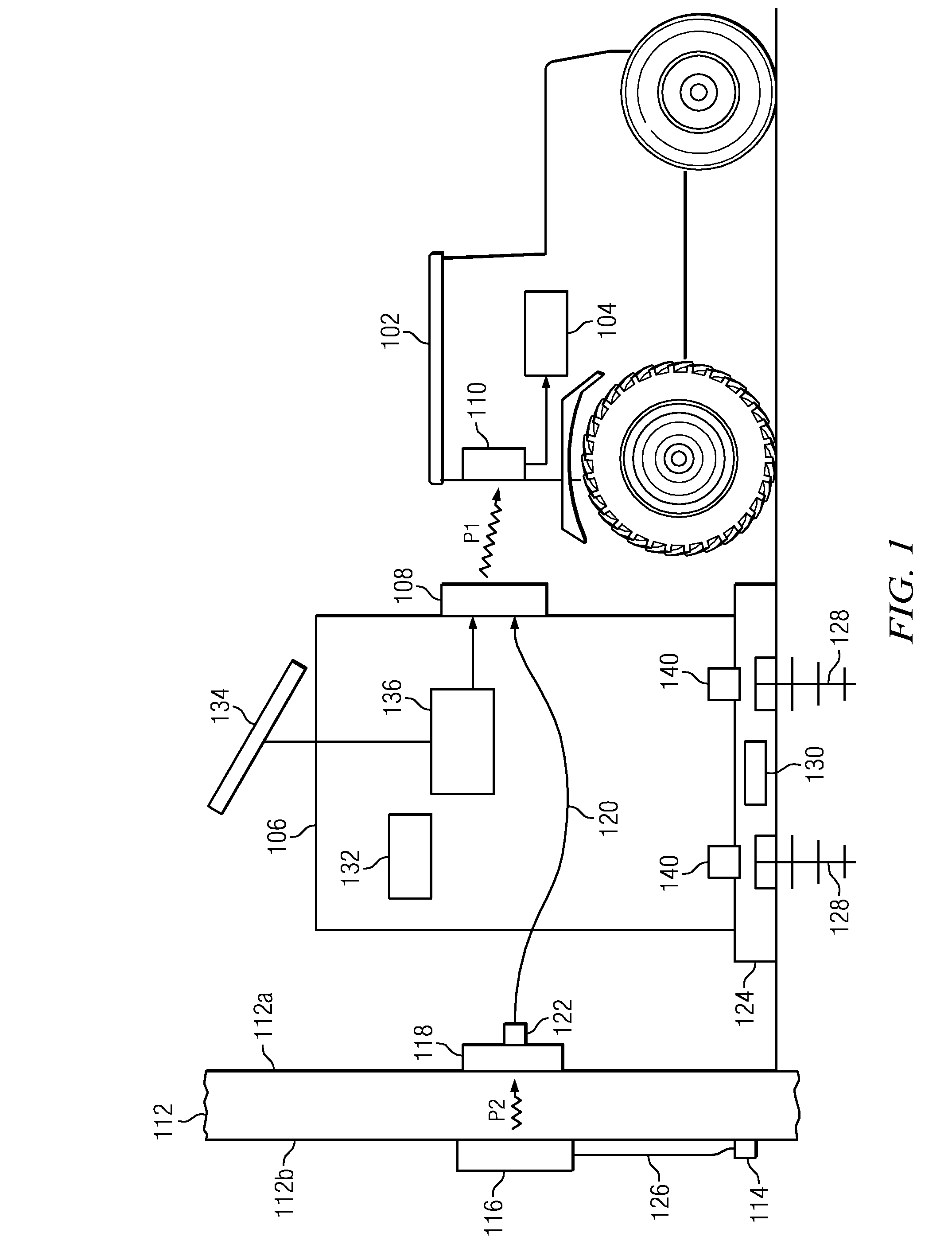
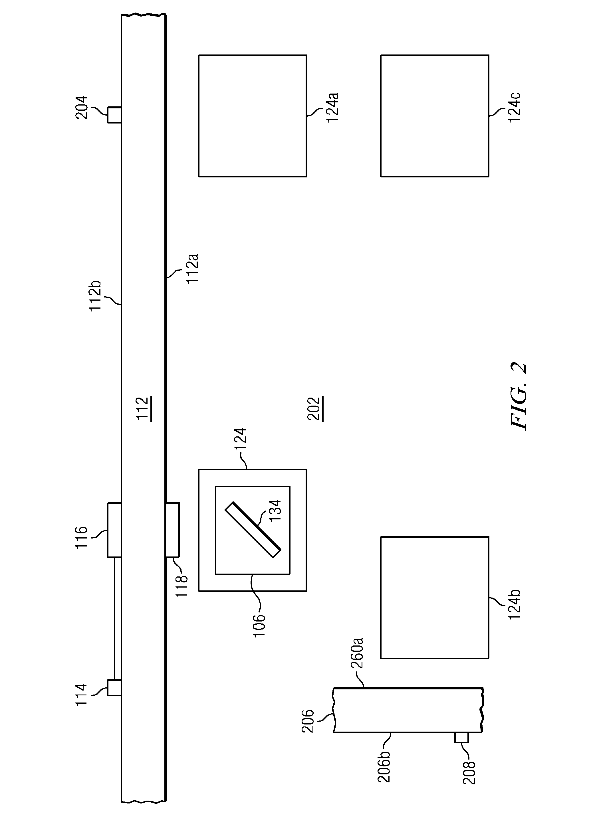
The invention disclosed and claimed herein pertains to a system and method for charging a battery used as a power source for a mobile robot or the like. More particularly, the invention pertains to a system and method of the above type that uses wireless power transmission, thus delivers more mobile robot durability, and is minimally destructive to the surrounding environment. Power charging stations for mobile outdoor service robots, such as robotic lawnmowers, are well known in the art. If a robot vehicle uses an electric battery as a source of power, the robot can be directed to the station whenever it is necessary to charge or recharge the battery. However, charging arrangements of this type, when used outdoors, can have significant drawbacks or deficiencies. As an example, in currently available systems, both the robot vehicle and the charging station have corresponding or complementary conductors or conductive elements. The conductive elements must be mated together, in order to transfer electric power from the station to the robot vehicle. However, these conductive elements are typically exposed to weather conditions and moisture, and over time may become oxidized and mechanically fatigued. Mud and debris can also collect on the conductive elements. As a result, the capability to transfer power to the robot, using these conductive elements, becomes degraded or diminished, and the overall system durability, compromised. Another problem with presently used outdoor charging systems is that an exterior or outdoor electric outlet will generally be required as a power source, but may not be conveniently available. For example, it may be desired to use a robotic lawnmower of the above type to mow a lawn which is adjacent to a house or other building that has no exterior outlet. Alternatively, the only exterior outlets could be on a side of the building that is opposite to the lawn that is to be mowed. In either case, it would be necessary to install an exterior outlet, which could be expensive and also destructive to the building. In addition, outdoor charging systems of the above type generally have only a single charging station. This can result in excessive wear of grass or other yard elements that are adjacent to the station, since the robotic mower must frequently go to and maneuver around this location. It might be possible to alleviate this problem by providing multiple charging stations at different locations. However, it would then be necessary to provide an exterior outlet at each of the multiple locations, which could further aggravate the problem discussed above in regard to the availability of such outlets, as well as increasing overall system cost. Embodiments of the invention are directed to a system for recharging a battery that is carried by a mobile robot or robot vehicle as a power source. The system comprises a power transmission link having a first end positioned at a selectively located charging station, and a second end connected to the battery carried by the robot, the transmission link being configured to transmit power from its first end to its second end to charge the battery. The system further comprises a first wireless power transmitter coupled to receive power from a specified power source, and a first wireless power receiver connected to the first end of the transmission link and located at a prespecified distance from the first wireless power transmitter. The first wireless power receiver is configured to receive power transmitted across the prespecified distance from the first wireless power transmitter, and to provide power to the first end of the transmission link, for transmission to charge the battery. The novel features believed characteristic of the illustrative embodiments are set forth in the appended claims. The illustrative embodiments, however, as well as a preferred mode of use, further objectives and advantages thereof, will best be understood by reference to the following detailed description of an illustrative embodiment of the present invention when read in conjunction with the accompanying drawings, wherein: Referring to At present, systems are available that can transfer power on the order of hundreds of watts from a wireless power transmitter to a wireless power receiver, when the transmitter and receiver are separated by a spacing on the order of twelve inches to three feet or more. Thus, in order to charge battery 104, robot 102 would be maneuvered by its control to position receiver 110 at a distance or spacing from transmitter 108 that is within a pre-specified range. The wireless transmitter 108 is then operated to transmit power P1 to wireless receiver 110, and receiver 110 couples the received power to recharge battery 104. The power transfer efficiency between transmitter and receiver drops as the distance between them grows. At some distance, it is impractical to transfer power between the transmitter and receiver. This defines the effective range of power transfer. It will appreciated that by using transmitter 108 and receiver 110 to transfer power, it is not necessary to mate or join complementary conductive elements together to effect power transfer, unlike certain prior art arrangements. Also, power can be transferred while transmitter 108 and receiver 110 are both kept tightly sealed, and thus protected against moisture, mud and the like. Referring further to In accordance with embodiments of the invention, it is intended to use the conventional interior outlet 114 as the power source for wireless transmitter 108, and thus as the source for charging battery 104. To accomplish this, By providing the components 116 and 118 arranged as shown by In different embodiments, the space between transmitter and receiver may be a material or structure other than a wall. The opposing sides of the space may be arbitrarily designated interior and exterior. In another embodiment, receiver 118 could be located with the housing of station 106. In embodiments of the invention, it may be useful to enable charging station 106 to be readily removable from base plate 124, such as for secure storage when it is not in use. Alternatively, station 106 may need to be periodically relocated, in order to minimize yard wear at any one location. Accordingly, conductor 120 may be detachably connected to receiver 118 such as by means of a plug and socket arrangement 122. Also, it may be desirable to securely attach station 106 to base plate 124, whenever the station is placed thereon. To ensure that base plate 124 is firmly connected to a location on the ground, anchors 128 are provided. Usefully, each anchor 128 is of a type that may be screwed into the ground by hand, to attach the plate 124, and may be unscrewed to release the plate. In general, anchor 128 may be any means which makes it difficult for unauthorized movement of charging station 106. For example, it may be desired to relocate the base plate 124. Also, to enhance security a tampering sensor 130 is placed in base plate 124, wherein the sensor 130 is a capacitive sensor that can detect a change in electrical permittivity under the station that is not explainable by soil moisture changes. For example, if a shovel was used by an unauthorized person to dig around the anchors 128, sensor 130 would detect the presence of a metallic shovel, the absence of dirt or the presence of air. If tampering is detected, an alarm or alerting device 132 would be activated. Device 132 could comprise, for example, a visual, audio, email or cell phone related device. Referring to Referring further to Referring to Base plate 304 is similar to base plate 124 in that anchors 128 are used therewith, and a tampering sensor 130 may be placed in the base plate 304. However, station 302 and plate 304 are permanently and securely joined together, such as by means of a hinge 306. Hinge 306 is positioned between plate 304 and the lower right corner of station 302, as viewed in Referring further to When the anchors are in place, the station 302 would be pivoted back to rest on plate 304. The locking mechanism would then be engaged, such as by locking padlock 310, so that station 302 would be retained in its rest position upon base plate 304. It is thus seen that a configuration comprising station 302 and base plate 304 can readily be moved from one location to another. At the same time, the configuration provides significant security measures to prevent unauthorized removal. The description of the different advantageous embodiments has been presented for purposes of illustration and description, and is not intended to be exhaustive or limited to the embodiments in the form disclosed. Many modifications and variations will be apparent to those of ordinary skill in the art. Further, different embodiments may provide different advantages as compared to other embodiments. The embodiment or embodiments selected are chosen and described in order to best explain the principles of the invention, the practical application, and to enable others of ordinary skill in the art to understand the invention for various embodiments with various modifications as are suited to the particular use contemplated. Embodiments of the invention are directed to a system for recharging a mobile robot as a power source. In one embodiment the system comprises a power transmission link having a first end positioned at a selectively located charging station and a second end connected to the battery carried by the robot, the transmission link being configured to transmit power from its first end to its second end to charge the battery. The system further comprises a first wireless power transmitter coupled to receive power from a specified power source, and a first wireless power receiver, connected to the first end of the transmission link and located at a prespecified distance from the first wireless power transmitter. The first wireless power receiver is configured to receive power transmitted across the prespecified distance from the first wireless power transmitter, and to provide power to the first end of the transmission link, for transmission to charge the battery. 1. An electrical power transfer station, comprising:
a power receiver wirelessly connectable to a power grid for receiving power; a structure having a housing, connectable to a base plate, having a power transmitter, wirelessly connectable to a device containing a battery, for transmitting the received power to the device for charging the battery; the base plate having a fixing means to a stationary support; and locking means to secure the fixing means to be tamper resistant. 2. The power transfer station of an alternate power source independent of the power grid for generating power used by the power transmitter to transmit the generated power to the device for charging the battery. 3. The power transfer station of 4. The power transfer station of 5. The power transfer station of 6. The power transfer station of 7. The power transfer station of 8. The power transfer station of 9. The power transfer station of a plurality of base plates placed at different locations in an area that is accessible by a mobile device; each base plate being adapted to receive and support the structure. 10. The power transfer station of the base plate is placed at a specified ground location wherein the ground is the stationary support, and the fixing means are removable anchor means provided to selectively retain the base plate at the ground location. 11. The power transfer station of releasable locking means are provided for selectively attaching the structure to, and releasing the structure from the base plate. 12. The power transfer station of the structure and base plate are continually joined together, and are disposed for movement in unison. 13. The power transfer station of the structure is selectively movable with respect to the base, in order to provide access to the anchor means, and means are provided to selectively prevent movement of the structure with respect to the base plate, in order to prevent access to the anchor means. 14. The power transfer station of the base plate is provided with a detector that is operable to detect efforts to remove the anchor means from the ground location. 15. The power transfer station of the base plate is further provided with an alarm that is responsive to operation of the detector. 16. The power transfer station of the alternative power source comprises an energy storage device and a power generating element selected from a group of elements that includes at least one of a solar call, a fuel cell, a wind generator and a piezo electric generator. 17. The power transfer station of 18. A method for setting up an electrical power transfer station, comprising the steps of:
wirelessly connecting a power receiver to a power grid for receiving power; connecting a structure to a base plate, the structure having a housing and a power transmitter, wirelessly connectable to a device containing a battery, for transmitting the received power to the device for charging the battery; furnishing fixing means to the base plate, for fixing the base plate to a stationary support; and using locking means to secure the fixing means to be tamper resistant. 19. The method of an alternate power source independent of the power grid is provided for generating power used by the power transmitter to transmit the generated power to the device for charging the battery. 20. The method of 21. The method of 22. The method of 23. The method of 24. The method of 25. The method of 26. The method of a plurality of base plates are placed at different locations in an area that is accessible by a mobile device; each base plate being adapted to receive and support the structure. 27. The method of the base plate is placed at a specified ground location wherein the ground is the stationary support, and the fixing means are removable anchor means provided to selectively retain the base plate at the ground location. 28. The method of releasable locking means are provided for selectively attaching the structure to, and releasing the structure from the base plate. 29. The method of the structure and base plate are continually joined together, and are disposed for movement in unison. 30. The method of the structure is selectively movable with respect to the base, in order to provide access to the anchor means, and means are provided to selectively prevent movement of the structure with respect to the base plate, in order to prevent access to the anchor means. 31. The method of the base plate is provided with a detector that is operable to detect efforts to remove the anchor means from the ground location. 32. The method of the base plate is further provided with an alarm that is responsive to operation of the detector. 33. The method of the alternate power source comprises an energy storage device and a power generating element selected from a group of elements that includes at least one of a solar call, a fuel cell, a wind generator and a piezo electric generator. 34. The method of FIELD OF THE INVENTION
BACKGROUND OF THE INVENTION
SUMMARY
BRIEF DESCRIPTION OF THE DRAWINGS
DESCRIPTION OF THE PREFERRED EMBODIMENT