ELECTRO-HYDRAULIC ACTUATION GROUP FOR AN AUTOMOTIVE SERVO-ASSISTED MECHANICAL TRANSMISSION
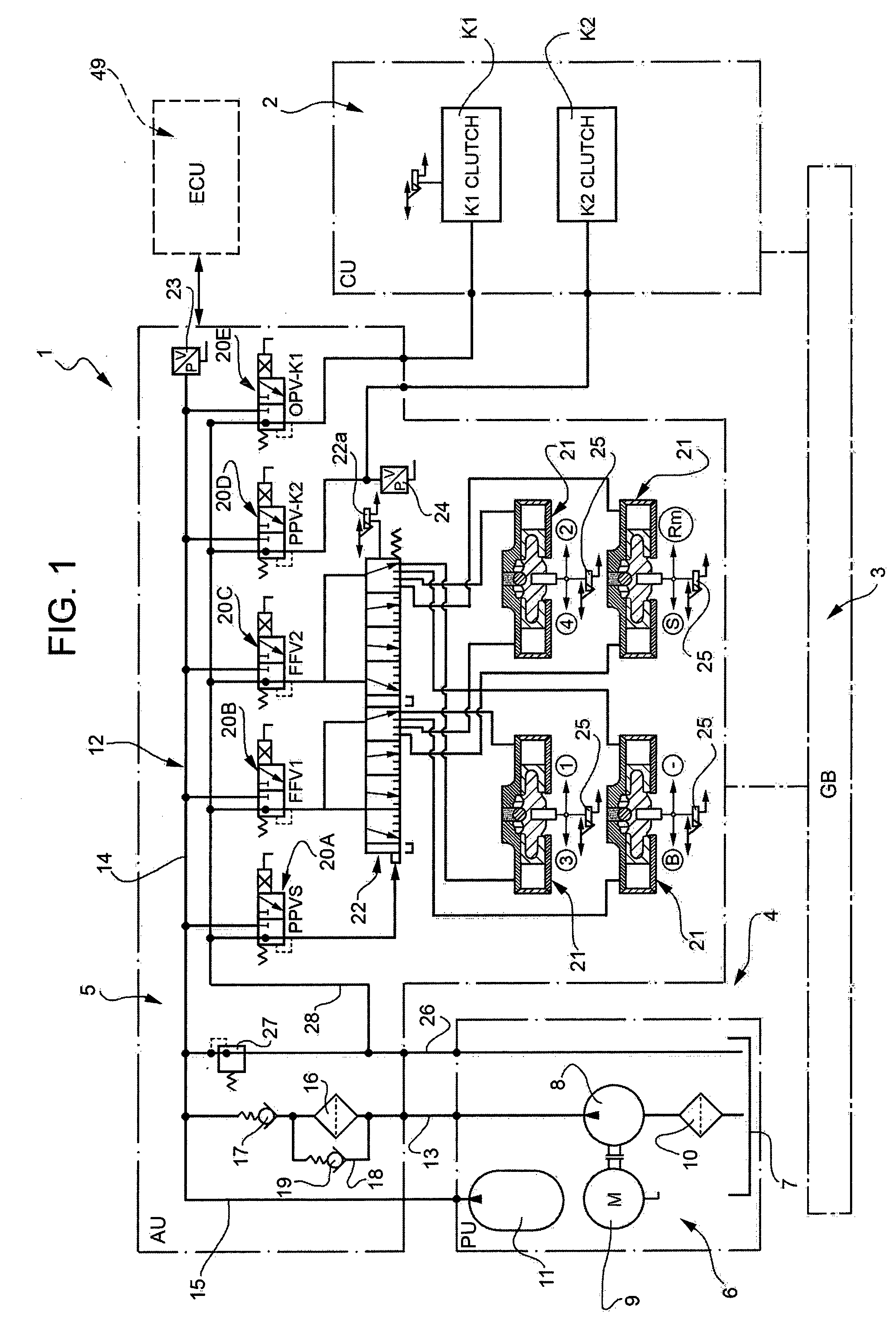
The present invention relates to an electro-hydraulic actuation group for an automotive servo-assisted mechanical transmission. In particular, the present invention finds particularly advantageous application in the case where the transmission is a dry dual clutch transmission, to which the description that follows will make explicit reference, but without any loss of generality. As is known, an automotive servo-assisted mechanical transmission comprises a clutch unit, a gearbox with electro-hydraulic actuation and an electro-hydraulic actuation group for operating the clutch unit and for selecting and engaging the gears in the gearbox. In general, an electro-hydraulic actuation group of known type can be broken down into three main subgroups: an actuation unit, which is provided with a hydraulic casing housing a hydraulic circuit and supporting a plurality of electrical and hydraulic components, a power unit that is able to supply the necessary hydraulic pressure for operating the actuation unit, and an electronic control unit able to control the actuation and power units. According to a commonly adopted known solution, the actuation and power units define two distinct assemblies inside the electro-hydraulic actuation group, which are arranged side-by-side and made integral with each other via a connection bracket that is rigidly connected to the hydraulic casing and acts as a support frame for the power unit's components. The actuation and power units assembled in this way are normally installed inside a housing outside the gearbox, next to electrical supply connections suitable for supplying the energy needed for operating the power and actuation units. According to what the Applicant has discovered through experience, the electro-hydraulic actuation groups configured according to the known art described above constitute, up to now, a solution that is not very satisfactory and poorly meets the needs, especially felt in the automotive sector, for cost containment and size reduction. In fact, given the arrangement of the power and actuation units, electro-hydraulic actuation groups of the above-described type suffer from the drawback of having relatively large bulk, outside of the gearbox, which makes their installation difficult and sometimes problematic. In addition, these groups require a relatively complex system of connections, both for the hydraulic connection of the power and actuation units to each other and for the electrical connections of the two units to the external power and control connections. Obviously, such complexity entails relatively high manufacturing, materials and installation costs, and therefore negatively affects not just the economic aspect, but also the reliability of the electro-hydraulic actuation group. The object of the present invention is to make an electro-hydraulic actuation group for an automotive servo-assisted mechanical transmission, this group being devoid of the above-described drawbacks. According to the present invention, an electro-hydraulic actuation group is made for an automotive servo-assisted mechanical transmission according to the attached claims. The invention shall now be described with reference to the enclosed drawings, which illustrate a non-limitative embodiment, where: According to the schematization in In particular, the AU block comprises an actuation unit 5 and the PU block comprises a power unit 6, which is connected to the actuation unit 5 to provide, during use, the same actuation unit 5 with the hydraulic pressure necessary for its operation. In the known manner, the power unit 6 comprises a tank 7 for the oil, a gear pump 8, which is driven by an electric motor 9 and is able to suck oil from the tank 7 through a suction filter 10, and a pressurised oil accumulator 11 connected to the pump 8. The actuation unit 5 comprises a hydraulic circuit 12, in turn comprising a feed line 13 that is connected to the delivery side of the pump 8, a distribution line 14 designed to receive oil under pressure from the feed line 13, and a supply line 15 connected to the accumulator 11. The supply line 15 also acts as a load line for the accumulator 11 during operation of the pump 8. The feed line 13 extends through a feed filter 16 and a non-return valve 17 placed in series and is equipped with a bypass line 18, which is designed to bypass the feed filter 16 in the feed direction of the oil and includes a non-return valve 19. The distribution line 14 has five branches able to supply oil under pressure to respective electro-hydraulic valves 20 (of known type), which are part of the actuation unit 5 and, in use, are operated by a transmission control unit (not shown in More in detail, as shown in the diagram in The hydraulic circuit 12 also comprises a plurality of sensors, including a position sensor 22 According to a variant that is not shown, the position sensor 22 Lastly, the hydraulic circuit 12 comprises an oil discharge line 26 that runs from the distribution line 14 to the tank 7 and is equipped with a pressure-relief valve 27 set to open when the pressure in the distribution line 14 exceeds a predetermined threshold. A collection line 28, connected to the respective discharge outlets of the five electro-hydraulic valves 20, also flows into the discharge line 26. In practice, the discharge line 26 and the tank 7 constitute a single collection system, from which oil is sucked by the pump 8 through the suction filter 10. The transmission 1 is electrically controlled by an electronic control unit (ECU), indicated in As shown in In particular, the actuation unit 5 comprises a generally parallelepipedal hydraulic casing 29 defined by an upper shell 30 and by a lower shell 31 rigidly connected to each other and defining, between them, part of the hydraulic circuit 12. The hydraulic casing 29 supports all the other components of the actuation unit 5, some of which are mounted externally on the hydraulic casing 29 and some of which are instead housed in respective seats obtained inside the upper 30 or lower 31 shell. As shown in On the opposite side of the hydraulic casing 29, the lower shell 31 supports a sensor module 34 housing a plurality of sensors, including position sensors 25, able to measure, in a known manner, respective quantities correlated to the operation of the electro-hydraulic actuation group 4. The sensor module 34 is fitted with an electrical connector 35 positioned at one end of the hydraulic casing 29 between the electro-hydraulic valves 20 and the tank 7. The position sensor 22 Lastly, the pressure sensor 24 associated with clutch K2 is mounted on a longitudinal end of the rib 32 on the opposite side from the electro-hydraulic valves 20 and is provided with an associated connector 36. At one end, the hydraulic casing 29 also supports the tank 7 and, at the opposite end, the feed filter 16, which comprises a cylindrical outer body having an axis substantially perpendicular to the connecting plane of the upper 30 and lower 31 shells. The actuation unit 5 is electrically connected to a control unit (not shown in As shown in Similarly, the signal line comprises a bundle of cables 40 having a watertight electrical output connector 41 and comprising a plurality of cables, fitted with respective watertight electrical connectors at their ends and connected to electrical connector 35 of sensor module 34, electrical connector 36 of pressure sensor 24 and electrical connector 22 As shown in On this point, it is opportune to specify that inside the hydraulic casing 29, the discharge line 26 is defined by a channel obtained partly in the upper shell 30 and partly in the lower shell 31 and is positioned along a peripheral portion of the hydraulic casing 29. In this way, since the pressure in the discharge line 26 is close to the ambient pressure, it is possible to avoid sealing problems along the connection portion of the shells, unlike what might occur if the above-mentioned connection portion was instead along a high-pressure channel of the hydraulic circuit 12. The electro-hydraulic actuation group 4 shown in With reference to As shown in La pump 8 and the motor 9 are mounted on the rib 32 and are aligned with each other along an axis parallel to the above-mentioned direction of insertion. In particular, the pump 8 finds itself on the same side as the accumulator 11 with respect to the rib 32, and the motor 9 finds itself on the same side as the electro-hydraulic valves 20; the electrical connector 44 of the motor 9 is positioned on a free axial end of the motor 9 and extends in a direction parallel to the above-mentioned direction of insertion. As shown in The suction filter 10 is mounted on the upper shell 30 at the side of feed filter 16, is parallel to the feed filter 16 and has an outlet that is directly connected to an inlet of the pump 8 and an inlet that tightly engages with an opening obtained in the upper shell 30 and directly facing the discharge line 26. The arrangement of the suction filter 10 beneath the pump 8 and in direct fluidic communication with the discharge line 26 has the advantage of not only eliminating the need for an external connection pipe between the suction filter 10 and the hydraulic casing 29, but also of establishing a suction level for the pump 8 capable of guaranteeing the correct operation of the pump 8 itself and eliminating the risk of cavitation phenomena arising. In fact, as is clearly noticeable in As shown in On opposite sides of the pressure sensor 24, the rib 32 has two communicating openings with respective outlets of two of the electro-hydraulic valves 20 and engaged by respective pipes able, in use, to feed oil under pressure to the hydraulic actuators of the clutches K1 and K2. With respect to that described above, it clearly emerges that the presence of components of both the actuation unit 5 and the power unit 6 on the hydraulic casing 29 endow the electro-hydraulic actuation group 4 with an extremely compact structure in terms of volume and weight, and enable a significant reduction in the number of hydraulic connection components for the various components, with consequent advantages in terms of low costs and system reliability. Furthermore, since the components of the power unit 6 are installed on the upper shell 30 such that the mechanical machining necessary for their positioning is in the same direction as those already present on the upper shell 30 (in particular the machining for the positioning of the motor 9, the pump 8 and the accumulator 11 is in the same direction of insertion of the electro-hydraulic valves 20), considerable savings are derived in terms of costs and machining and assembly times for the electro-hydraulic actuation group 4. The embodiment shown in As previously described, the components of the actuation unit 5 and power unit 6 are positioned on the hydraulic casing 29 so that the respective electrical connections are all arranged on the same side of the hydraulic casing 29, extending in respective directions parallel to the above-mentioned direction of insertion of the electro-hydraulic valves 20 and are therefore able to all be simultaneously engaged, in a same direction of coupling, by a single connection element. In particular, as shown in The electrical connector 44 of the motor 9, the electrical connectors 33 of the electro-hydraulic valves 20, the electrical connector 36 of the pressure sensor 24, the electrical connector 35 of the sensor module 34 and, lastly, the electrical connector 22 In particular, the multiple electrical connector 46 is mounted on the shell 30, extending along the shell 30 itself from the motor 9 up to the tank 7 so as to completely cover the electro-hydraulic valves 20 and comprises a plurality of internal electrical connectors (not visible in the attached figures), each of which is connected to a respective electrical connector of a component of the actuation unit 5 and power unit 6 and is electrically connected to the electrical input/output connector 47 via a respective watertight electrically conductive track 50 (of known type and schematically indicated in The multiple electrical connector 46 is preferable made of a plastic material and is fixed to the upper shell 30 in a removable manner by screws or other fixing devices of known type. In addition, as shown in The multiple electrical connector 46 can be designed to carry out a plurality of functions, based on technical choices and on the possible arrangement of the electronic components needed by the system. In the example shown, the multiple electrical connector 46 comprises the above-mentioned electrical connectors (not shown) and the tracks 50, while other electronic components, such as the electrical actuator for piloting the motor 9 (known as a Smart Drive), remain separate from the multiple electrical connector 46; furthermore, in this case, the electronic control unit 49 comprises both the power electronics and the control electronics for piloting the electro-hydraulic valves 20 and the electro-hydraulic valve 22. According to an embodiment not shown, the multiple electrical connector 46 also comprises the electrical actuator for piloting the motor 9 and the power electronics for piloting the electro-hydraulic valves 20, while the electronic control unit 49 comprises just the control electronics; in this case, the electrical input/output connector 47 comprises signal terminals and electric power supply terminals. In an automotive servo-assisted mechanical transmission, an electro-hydraulic actuation group has an actuation unit, a power unit able to provide hydraulic pressure to the actuation unit and an electronic control unit, the actuation and power units being equipped with respective components that are all mounted on a hydraulic casing of the actuation unit so as to define with one another a single assembly, at least part of the components being equipped with respective electrical connectors that are arranged in a manner such that they can all be engaged by a same multiple electrical connector device, electrically connectable to the electronic control unit. 1. An electro-hydraulic actuation group for an automotive servo-assisted mechanical transmission, the electro-hydraulic actuation group comprising an actuation unit, a power unit designed to provide hydraulic pressure to the actuation unit and an electronic control unit; the power unit comprising first components including a pump and an electric motor, which is designed to operate the pump and is provided with a first electrical connector, and the actuation unit comprising a hydraulic casing, second components provided with second electrical connectors, and a hydraulic circuit fluidically connected to the pump to supply, in use, a fluid under pressure to the second components; the hydraulic casing comprising a first and a second shell, which are rigidly connected to each other and define at least part of said hydraulic circuit therebetween; the first shell having an outer surface located on the side of the hydraulic casing facing away from the second shell; and the second components comprise electro-hydraulic valves, which are configured to actuate respective servo-assisted members of the transmission, are housed in respective seats provided on said outer surface of the first shell and are fitted with respective second electrical connectors; a sensor module carried by the second shell and fitted with a respective second electrical connector; and a pressure sensor, which is associated to an outlet of one of the electro-hydraulic valves, is carried by the first shell and is fitted with a respective second electrical connector; the electro-hydraulic actuation group being characterized in that the first and the second components all are directly mounted on the hydraulic casing so as to define a single assembly; and in that the first and second electrical connectors are arranged such that they can all be engaged by a same multiple electrical connector device, which is mounted on said outer surface of the first shell in a removable manner and is provided with an electrical input/output interface for the electrical connection of the actuation unit and the power unit with the electronic control unit. 2. The electro-hydraulic actuation group according to 3. The electro-hydraulic actuation group according to 4. The electro-hydraulic actuation group according to 5. The electro-hydraulic actuation group according to 6. The electro-hydraulic actuation group according to 7. The electro-hydraulic actuation group according to 8. An automotive servo-assisted mechanical transmission comprising an electro-hydraulic actuation group according to TECHNICAL FIELD OF THE INVENTION
STATE OF THE ART
DISCLOSURE OF THE INVENTION
BRIEF DESCRIPTION OF THE DRAWINGS
PREFERRED EMBODIMENTS OF THE INVENTION