PROCESSING METHOD AND PROCESSING DEVICE FOR CONCAVE-CONVEX GEAR
The invention relates to a machining method and machining device for a concave-convex gear. There is a nutation gear set as one of reduction gears. The nutation gear set is, for example, described in Patent Document 1. That is, the nutation gear set is formed of a first gear, a second gear and an input shaft that have the same rotation central axis, and a nutation gear that performs differential rotation with respect to the first gear and the second gear while wobbling therebetween. The nutation gear is supported by the input shaft so as to be rotatable about an inclined rotation central axis. Furthermore, the inclined rotation central axis relatively rotates about the rotation central axis of the first gear with the rotation of the input shaft. By so doing, the nutation gear wobbles with respect to the first gear and the second gear. Then, first nutation teeth that mesh with the first gear are formed on a face of the nutation gear, adjacent to the first gear, and second nutation teeth that mesh with the second gear are formed on a face of the nutation gear, adjacent to the second gear. Then, as the nutation gear wobbles, differential rotation occurs between the first gear and the nutation gear or between the second gear and the nutation gear. That is, when the second gear is set as an output shaft with respect to the input shaft, speed may be reduced at a large reduction gear ratio. The nutation gear has an extremely complex meshing face that meshes with the first gear or the second gear, so machining is not easy. A machining device for the nutation gear is, for example, described in Patent Document 1. Patent Document 1: Japanese Patent Application Publication No. 2006-272497 Incidentally, various machining methods of machining gears, such as a spur gear and a bevel gear, have been proposed and implemented. Machining of a nutation gear is also implemented using a special purpose machine as described in Patent Document 1; however, a special machining device is used or a special technique is required, so it is not considered to be easy. The invention is contemplated in view of such a situation, and it is an object of the invention to provide a new machining method and machining device for a concave-convex gear. In order to solve the above problem, the invention extracts a relative movement trajectory between each convex tooth of a mating gear and a corresponding one of concave teeth of a concave-convex gear that is a machining target at the time of differential rotation and then moves a working tool and a disc-shaped workpiece such that a relative movement trajectory between the working tool and the disc-shaped workpiece coincides with the extracted relative movement trajectory between each convex tooth of the mating gear and the concave-convex gear at the time of machining the concave teeth of the concave-convex gear on the disc-shaped workpiece. A feature of the invention according to claim 1 provides a machining method for a concave-convex gear, concave teeth of the concave-convex gear and convex teeth of a mating gear being continuously formed in a circumferential direction, and the concave teeth meshing with the convex teeth of the mating gear to allow torque transmission to or from the mating gear. The machining method includes: a trajectory extracting step of extracting a relative movement trajectory of each convex tooth of the mating gear with respect to the concave-convex gear that serves as a machining target at the time when torque is transmitted between the mating gear and the concave-convex gear; and a machining step of, when the concave teeth of the concave-convex gear are machined on a concave tooth forming face of a disc-shaped workpiece that is the concave-convex gear on which the concave teeth have not been machined, moving at least one of the disc-shaped workpiece and a working tool such that a relative movement trajectory of the working tool with respect to the disc-shaped workpiece coincides with the relative movement trajectory of each convex tooth of the mating gear with respect to the concave-convex gear, extracted in the trajectory extracting step. A feature of the invention according to claim 2 is such that, in claim 1, the concave-convex gear is a gear that rotates about an intersecting axis that intersects with a rotation central axis of the mating gear. A feature of the invention according to claim 3 is such that, in claim 1 or 2, the number of the convex teeth of the mating gear is different from the number of the concave teeth of the concave-convex gear. A feature of the invention according to claim 4 is such that, in any one of claims 1 to 3, in the trajectory extracting step, a relative movement trajectory of a reference axis of each convex tooth of the mating gear with respect to the concave-convex gear is extracted, and the reference axis is an axis that is parallel to a line of intersection of a tooth thickness central plane and reference conical surface of each convex tooth of the mating gear. A feature of the invention according to claim 5 is such that, in any one of claims 1 to 4, the mating gear includes a mating gear body that is integrally formed with the convex teeth or the mating gear body that is separately formed from the convex teeth and that supports the convex teeth, and a sectional shape of an outer peripheral surface of each convex tooth of the mating gear in a direction orthogonal to a reference axis of the convex tooth is formed in a circular arc shape. A feature of the invention according to claim 6 is such that, in claim 5, the working tool is a disc-shaped tool, and, in the machining step, each convex tooth of the mating gear is spuriously expressed by the disc-shaped tool through infeed operation at multiple portions at which a central axis of the disc-shaped tool is shifted in a tooth groove direction of a corresponding one of the concave teeth of the concave-convex gear to machine the concave teeth of the concave-convex gear with the disc-shaped tool. A feature of the invention according to claim 7 is such that, in claim 6, the machining method includes: a simulation step of performing machining simulation by moving at least one of the disc-shaped workpiece and the working tool; and a cutting position calculation step of comparing a preset ideal shape model with a shape of a result of the machining simulation to calculate a position of infeed operation by shifting the central axis of the disc-shaped tool in the tooth groove direction of each concave tooth of the concave-convex gear, wherein in the machining step, the concave teeth of the concave-convex gear are machined on the basis of the position of infeed operation, calculated in the cutting position calculation step. A feature of the invention according to claim 8 is such that, in claim 7, in the cutting position calculation step, the position of the infeed operation is calculated so that a machining time is minimized while a deviation between the shape of the result of the machining simulation and the ideal shape model is smaller than or equal to a set permissible value. A feature of the invention according to claim 9 is such that, in claim 5, the working tool is formed in a pin shape that is coincident with or similar to an outer peripheral shape of each convex tooth of the mating gear and that rotates about a pin central axis. A feature of the invention according to claim 10 is such that, in claim 5, the working tool is a circulating belt-shaped tool and has a straight portion in a circulating direction. A feature of the invention according to claim 11 is such that, in any one of claims 1 to 10, the machining method includes a coordinate conversion step of calculating a movement trajectory of the working tool in a workpiece coordinate system by subjecting the relative movement trajectory of each convex tooth with respect to the concave-convex gear, extracted in the trajectory extracting step, to coordinate conversion, and in the machining step, at least one of the disc-shaped workpiece and the working tool is moved on the basis of the movement trajectory of the working tool, calculated in the coordinate conversion step. A feature of the invention according to claim 12 is such that, in claim 11, the concave-convex gear is a gear that rotates about an intersecting axis that intersects with a rotation central axis of the mating gear, a sectional shape of an outer peripheral surface of each convex tooth of the mating gear in a direction orthogonal to a reference axis of the convex tooth is formed in a circular arc shape, a relative movement trajectory of each convex tooth of the mating gear with respect to the concave-convex gear, extracted in the trajectory extracting step, is decomposed into: a first linear axis along which a reference position of the convex tooth of the mating gear is moved in a direction orthogonal to a plane that is tangent to a concave tooth forming face of the disc-shaped workpiece; a second linear axis along which the reference position of the convex tooth of the mating gear is moved in a tooth groove direction of a corresponding one of the concave teeth of the concave-convex gear in the plane that is tangent to the concave tooth forming face of the disc-shaped workpiece; a third linear axis along which the reference position of the convex tooth of the mating gear is moved in a direction orthogonal to the second linear axis in the plane that is tangent to the concave tooth forming face of the disc-shaped workpiece; a fourth rotation axis along which the reference position of the convex tooth of the mating gear is rotated about the first linear axis; a fifth rotation axis along which the reference position of the convex tooth of the mating gear is rotated about the third linear axis; and a sixth indexing axis that coincides with a rotation central axis of the concave-convex gear and that indexes a rotation phase of the concave-convex gear, in the coordinate conversion step, the relative movement trajectory of each convex tooth of the mating gear, expressed by the first linear axis, the third linear axis, the fourth rotation axis, the fifth rotation axis and the sixth indexing axis when movement of the reference position of the convex tooth of the mating gear along the second linear axis is assumed to be performed along the third linear axis is calculated in the case where it is presumed that a tooth length of each convex tooth of the mating gear is infinite, and in the machining step, at least one of the disc-shaped workpiece and the working tool is moved on the basis of the calculated relative movement trajectory. A feature of the invention according to claim 13 is such that, in claim 11, the concave-convex gear is a gear that rotates about an intersecting axis that intersects with a rotation central axis of the mating gear, a sectional shape of an outer peripheral surface of each convex tooth of the mating gear in a direction orthogonal to a reference axis of the convex tooth is formed in a circular arc shape, a relative movement trajectory of each convex tooth of the mating gear with respect to the concave-convex gear, extracted in the trajectory extracting step, is decomposed into: a first linear axis along which a reference position of the convex tooth of the mating gear is moved in a direction orthogonal to a plane that is tangent to a concave tooth forming face of the disc-shaped workpiece; a second linear axis along which the reference position of the convex tooth of the mating gear is moved in a tooth groove direction of a corresponding one of the concave teeth of the concave-convex gear in the plane that is tangent to the concave tooth forming face of the disc-shaped workpiece; a third linear axis along which the reference position of the convex tooth of the mating gear is moved in a direction orthogonal to the second linear axis in the plane that is tangent to the concave tooth forming face of the disc-shaped workpiece; a fourth rotation axis along which the reference position of the convex tooth of the mating gear is rotated about the first linear axis; a fifth rotation axis along which the reference position of the convex tooth of the mating gear is rotated about the third linear axis; and a sixth indexing axis that coincides with a rotation central axis of the concave-convex gear and that indexes a rotation phase of the concave-convex gear, in the coordinate conversion step, the relative movement trajectory of each convex tooth of the mating gear, expressed by the first linear axis, the second linear axis, the fourth rotation axis, the fifth rotation axis and the sixth indexing axis when movement of the reference position of the convex tooth of the mating gear along the third linear axis is assumed to be performed along the second linear axis is calculated in the case where it is presumed that a tooth length of each convex tooth of the mating gear is infinite, and in the machining step, at least one of the disc-shaped workpiece and the working tool is moved on the basis of the calculated relative movement trajectory. A feature of the invention according to claim 14 is such that, in claim 11, the concave-convex gear is a gear that rotates about an intersecting axis that intersects with a rotation central axis of the mating gear, a sectional shape of an outer peripheral surface of each convex tooth of the mating gear in a direction orthogonal to a reference axis of the convex tooth is formed in a circular arc shape, a relative movement trajectory of each convex tooth of the mating gear with respect to the concave-convex gear, extracted in the trajectory extracting step, is decomposed into: a first linear axis along which a reference position of the convex tooth of the mating gear is moved in a direction orthogonal to a plane that is tangent to a concave tooth forming face of the disc-shaped workpiece; a second linear axis along which the reference position of the convex tooth of the mating gear is moved in a tooth groove direction of a corresponding one of the concave teeth of the concave-convex gear in the plane that is tangent to the concave tooth forming face of the disc-shaped workpiece; a third linear axis along which the reference position of the convex tooth of the mating gear is moved in a direction orthogonal to the second linear axis in the plane that is tangent to the concave tooth forming face of the disc-shaped workpiece; a fourth rotation axis along which the reference position of the convex tooth of the mating gear is rotated about the first linear axis; a fifth rotation axis along which the reference position of the convex tooth of the mating gear is rotated about the third linear axis; and a sixth indexing axis that coincides with a rotation central axis of the concave-convex gear and that indexes a rotation phase of the concave-convex gear, in the coordinate conversion step, the relative movement trajectory of each convex tooth of the mating gear, expressed by the first linear axis, the second linear axis, the third linear axis, the fourth rotation axis and the sixth indexing axis is calculated by decomposing movement of the reference position of the convex tooth of the mating gear along the fifth rotation axis into movement along the first linear axis and movement along the second linear axis, and in the machining step, at least one of the disc-shaped workpiece and the working tool is moved on the basis of the calculated relative movement trajectory. A feature of the invention according to claim 15 is such that, in claim 11, the concave-convex gear is a gear that rotates about an intersecting axis that intersects with a rotation central axis of the mating gear, a sectional shape of an outer peripheral surface of each convex tooth of the mating gear in a direction orthogonal to a reference axis of the convex tooth is formed in a circular arc shape, a relative movement trajectory of each convex tooth of the mating gear with respect to the concave-convex gear, extracted in the trajectory extracting step, is decomposed into: a first linear axis along which a reference position of the convex tooth of the mating gear is moved in a direction orthogonal to a plane that is tangent to a concave tooth forming face of the disc-shaped workpiece; a second linear axis along which the reference position of the convex tooth of the mating gear is moved in a tooth groove direction of a corresponding one of the concave teeth of the concave-convex gear in the plane that is tangent to the concave tooth forming face of the disc-shaped workpiece; a third linear axis along which the reference position of the convex tooth of the mating gear is moved in a direction orthogonal to the second linear axis in the plane that is tangent to the concave tooth forming face of the disc-shaped workpiece; a fourth rotation axis along which the reference position of the convex tooth of the mating gear is rotated about the first linear axis; a fifth rotation axis along which the reference position of the convex tooth of the mating gear is rotated about the third linear axis; and a sixth indexing axis that coincides with a rotation central axis of the concave-convex gear and that indexes a rotation phase of the concave-convex gear, in the coordinate conversion step, the relative movement trajectory of each convex tooth of the mating gear, expressed by the first linear axis, the second linear axis, the third linear axis, the fifth rotation axis and the sixth indexing axis when the fourth rotation axis is brought into coincidence with the sixth indexing axis is calculated, and in the machining step, at least one of the disc-shaped workpiece and the working tool is moved on the basis of the calculated relative movement trajectory. A feature of the invention according to claim 16 provides a machining device for a concave-convex gear in which concave teeth and convex teeth are continuously formed in a circumferential direction and the concave teeth mesh with convex teeth of a mating gear to allow torque transmission to or from the mating gear. The machining device includes: trajectory extracting means for extracting a relative movement trajectory of each convex tooth of the mating gear with respect to the concave-convex gear that serves as a machining target at the time when torque is transmitted between the mating gear and the concave-convex gear; and machining means for, when the concave teeth of the concave-convex gear are machined on a concave tooth forming face of a disc-shaped workpiece that is the concave-convex gear on which the concave teeth have not been machined, moving at least one of the disc-shaped workpiece and a working tool such that a relative movement trajectory of the working tool with respect to the disc-shaped workpiece coincides with the relative movement trajectory of each convex tooth of the mating gear with respect to the concave-convex gear, extracted in the trajectory extracting step. With the invention according to claim 1 configured as described above, an NC machine tool is used to make it possible to machine the concave teeth of the concave-convex gear. That is, the same NC machine tool may be used to machine concave-convex gears having various shapes. Specifically, an NC program is generated on the basis of the relative movement trajectory extracted in the trajectory extracting step, and the concave teeth of the concave-convex gear may be machined in the machining step using the NC program. In this way, it is possible to extremely easily machine the concave teeth of the concave-convex gear. Here, in the concave-convex gear that rotates about an intersecting axis with respect to a mating gear (hereinafter, also referred to as “concave-convex gear with an intersecting axis”), the meshing rate of the mating gear and the concave-convex gear increases. Therefore, it is possible to reduce size, increase strength and achieve quietness. On the other hand, in order to achieve desirable tooth contact, it is required to form a tooth flank shape having an extremely high accuracy, so there is a problem that machining of a tooth flank shape is not easy. In contrast to this, with the invention according to claim 2, the concave teeth of the concave-convex gear with an intersecting axis may be easily and highly accurately formed. As a result, according to the invention, it is possible to reduce machining cost in the case of accuracy equivalent to the existing art. Note that, other than the concave-convex gear with an intersecting axis, the invention may be applied to a concave-convex gear with a parallel axis, that is, a so-called spur gear. With the invention according to claim 3, because the number of teeth of the mating gear is different from the number of teeth of the concave-convex gear, so it is configured such that torque is transmittable while the mating gear and the concave-convex gear perform differential rotation. Then, because the number of teeth is different therebetween, the shape of each concave tooth of the concave-convex gear is an extremely complex shape. In such a case as well, by applying the invention, it is possible to reliably machine the concave teeth of the concave-convex gear. Note that, when the number of teeth of the mating gear is equal to the number of teeth of the concave-convex gear, that is, when torque is transmitted while rotating at the same number of revolutions as well, the machining method according to the invention is, of course, applicable. With the invention according to claim 4, although the relative movement between the concave-convex gear and the mating gear is three-dimensional complex movement, the reference axis is used to make it possible to reliably understand the relative movement trajectory. Here, the reference conical surface is a surface that passes through the reference pitch circle of each cross section. The case where a cone angle of 0° or a cone angle of 180° is included. In addition, the tooth thickness central plane of each convex tooth of the mating gear means the central plane of each convex tooth in a circumferential width. With the invention according to claim 5, the sectional shape of each convex tooth of the mating gear in the direction orthogonal to the reference axis is a circular arc shape. By so doing, the mating gear and the concave-convex gear are able to extremely smoothly transmit torque. On the other hand, machining of the concave teeth of the concave-convex gear becomes complicated. Because the sectional shape of each convex tooth of the mating gear in the direction orthogonal to the reference axis is a circular arc shape, each concave tooth of the concave-convex gear has a sectional shape approximate to a circular arc concave shape as a whole, and, specifically, has a sectional shape of which the opening edge portions of the circular arc concave shape are sagged. In this way, even when each concave tooth of the concave-convex gear has a complex shape, the invention is applied to make it possible to reliably and highly accurately perform machining. As a result, it is possible to form the nutation gear 15 having high performance at low cost. Note that, even when each convex tooth of the mating gear is formed in a shape other than a pin shape, the machining method of the invention may be applied. With the invention according to claim 6, by using the disc-shaped tool to spuriously express a pin-shaped convex tooth, it is possible to reliably machine the concave teeth of the concave-convex gear. Furthermore, by using the disc-shaped tool, the stiffness of the tool may be enhanced, so it is possible to perform machining with high accuracy. With the invention according to claim 7, machining is performed on the basis of the position of the infeed operation, obtained through comparison between the ideal shape model and the simulation model, so it is possible to form the highly accurate concave teeth of the concave-convex gear. With the invention according to claim 8, it is possible to calculate a machining condition with a shortest period of time while ensuring machining accuracy within the permissible value. With the invention according to claim 9, when the working tool has a shape that is coincident with or similar to each convex tooth of the mating gear, movement of the working tool is set so as to be similar to that of each convex tooth of the mating gear to thereby make it possible to form the optimal concave teeth of the concave-convex gear. With the invention according to claim 10, it is possible to easily express each convex tooth of the mating gear owing to the straight portion of the belt-shaped tool. Thus, by setting movement of the straight portion of the belt-shaped tool so as to be similar to each convex tooth of the mating gear, it is possible to form the optimal concave teeth of the concave-convex gear. With the invention according to claim 11, the relative movement trajectory of each convex tooth of the mating gear is converted to movement of the working tool in the workpiece coordinate system. Here, in the trajectory extracting step, the relative movement trajectory of each convex tooth of the mating gear with respect to the concave-convex gear at the time of torque transmission is extracted. Then, depending on the type of working tool, the relative movement trajectory extracted in the trajectory extracting step and the movement trajectory of the working tool in the workpiece coordinate system differ from each other. That is, owing to the invention, the NC program based on the type of working tool may be generated. With the invention according to claim 12, movement along the second linear axis is omitted to make it possible to allow machining with five axes. With the invention according to claim 13, movement along the third linear axis is omitted to make it possible to allow machining with five axes. With the invention according to claim 14, the fifth rotation axis is omitted to make it possible to allow machining with five axes. In this case, the disc-shaped tool is desirably used as the working tool to form a spurious convex tooth of the mating gear. With the invention according to claim 15, movement along the fourth rotation axis is omitted to make it possible to allow machining with five axes. With the invention according to claim 16, similar advantageous effects to those of the invention of the machining method according to claim 1 are obtained. In addition, in the invention of the machining device, the above described other features related to the machining method may also be applied as the machining device. In this case, similar advantageous effects to the advantageous effects based on the respective features are obtained. Hereinafter, specific embodiments of a machining method and machining device for a concave-convex gear according to the invention will be described with reference to the drawings. Here, a nutation gear set is formed of two pairs of the relationship between a concave-convex gear and a mating gear in the case where a rotation central axis of the concave-convex gear intersects with a rotation central axis of the mating gear. In the present embodiments, a machining method and machining device for a nutation gear of a nutation gear set will be described by way of example. Note that, in the following description, a nutation gear corresponds to a “concave-convex gear” according to the invention, and a fixed shaft 12 and an output shaft 13 each correspond to a “mating gear” according to the invention. Six-Axis Configuration (Three Linear Axes and Three Rotation Axes) A machining method and machining device for a nutation gear of a nutation gear set according to a first embodiment will be described with reference to (1) Configuration of Nutation Gear Set The configuration of the nutation gear set that uses the nutation gear that is a machining object of the invention will be described with reference to The nutation gear set is used as a reduction gear, and is able to obtain an extremely large reduction gear ratio. As shown in The input shaft 11 constitutes a rotor of a motor (not shown), and is a shaft that rotates as the motor is driven. The input shaft has a cylindrical shape, and rotates about a rotation central axis A (shown in The fixed shaft 12 (that corresponds to the “mating gear” of the invention) is fixed to a housing (not shown). The fixed shaft 12 is formed of the fixed shaft body 12 In addition, in the above description, as shown in The output shaft 13 (that corresponds to the “mating gear” of the invention) is supported by the housing (not shown) so as to be rotatable about the rotation central axis A, and is coupled to an output member (not shown). The output shaft 13 is formed of the output shaft body 13 A plurality (G4) of the convex tooth pins 13 In addition, in the above description, the convex tooth pins 13 The outer ring 14 is formed in a cylindrical shape, and has a raceway surface on its inner peripheral surface. The outer ring 14 is press-fitted to the inclined surface 11 a of the input shaft 11. That is, the outer ring 14 is integrated with the input shaft 11, and is rotatable about the rotation central axis B. The inner ring 15 (that corresponds to the “concave-convex gear” of the invention) is formed in a substantially cylindrical shape. A rolling surface 15 The inner ring 15 is arranged on a radially inner side of the outer ring 14, and holds the plurality of rolling elements (balls) 16. That is, the inner ring 15 has the rotation central axis B that is inclined with respect to the rotation central axis A. Thus, the inner ring 15 is rotatable about the rotation central axis B with respect to the input shaft 11. Furthermore, the inner ring 15 is rotatable about the rotation central axis A as the input shaft 11 rotates about the rotation central axis A through driving of the motor. Furthermore, the inner ring 15 is arranged between the fixed shaft 12 and the output shaft 13 in the axial direction. Specifically, the inner ring 15 is arranged between the axial end face of the fixed shaft body 12 Then, because the inner ring 15 wobbles about the rotation central axis A with respect to the fixed shaft 12, part (upper part in Then, for example, the number of teeth Z1 of the convex tooth pins 12 In the nutation gear set shown in Here, each of the nutation concave teeth 15 (2) Machining Method and Machining Device for Nutation Gear (2.1) Basic Concept of Machining Method for Nutation Gear Next, a machining method for the nutation concave teeth 15 Subsequently, the relative movement trajectory of each convex tooth pin 12 Subsequently, the extracted relative movement trajectory of each convex tooth pin 12 Subsequently, at least one of a disc-shaped workpiece and the working tool is moved on the basis of the generated NC program (S4) (that corresponds to “machining step” and “machining means” of the invention). That is, at least one of the disc-shaped workpiece and the working tool is moved such that the relative movement trajectory of the working tool with respect to the disc-shaped workpiece coincides with the movement trajectory of each convex tooth pin 12 Hereinafter, the trajectory extracting step, the coordinate conversion step and the machining step will be described in detail. (2.2) Trajectory Extracting Step (Trajectory Extracting Means) The trajectory extracting step will be described with reference to In a state before the convex tooth pin 12 Subsequently, in a state where the convex tooth pin 12 Subsequently, in a state where the convex tooth pin 12 That is, the movement trajectory of the reference axis 12X of the convex tooth pin 12 That is, the first linear axis is an axis along which the reference position (predetermined position) of the convex tooth pin 12 The fourth rotation axis is an axis along which the reference position of the convex tooth pin 12 (2.3) Coordinate Conversion Step (Coordinate Conversion Means) Here, the subject machine tool in the present embodiment has a machine configuration having first to sixth axes. That is, the NC program in the present embodiment is expressed by the three linear axes and the three rotation axes as in the case of the above described movement trajectory of each convex tooth pin 12 (2.4) Machining Step (Machining Means) The working tool in the present embodiment may be any tool as long as it is possible to express the outer peripheral shape of the convex tooth pin 12 Then, in the machining step, machining is performed on the basis of the NC program subjected to coordinate conversion in the coordinate conversion step. That is, as shown in (3) Advantageous Effects of First Embodiment According to the present embodiment, a six-axis NC machine tool is used to make it possible to machine the nutation concave teeth 15 In addition, the nutation gear 15 is a concave-convex gear that rotates about an intersecting axis with respect to a mating gear (the fixed shaft 12 or the output shaft 13). Because of such a configuration, the meshing rate of both gears increases. Therefore, it is possible to reduce size, increase strength and achieve quietness. On the other hand, in order to achieve desirable tooth contact, it is required to form a tooth flank shape having an extremely high accuracy, so there is a problem that machining of a tooth flank shape is not easy. In contrast to this, by applying the machining method according to the present embodiment, the nutation concave teeth 15 Here, because the number of teeth Z1 of the convex tooth pins 12 Furthermore, the sectional shape of the convex tooth pin 12 In addition, relative movement between the nutation gear 15 and the fixed shaft 12 is three-dimensionally complex movement; however, the reference axis 12X of the convex tooth pin 12 In addition, when the working tool has a shape that is coincident with or similar to the convex tooth pin 12 In addition, the relative movement trajectory of the convex tooth pin 12 A machining method and machining device for a nutation gear of a nutation gear set according to a second embodiment will be described with reference to Here, in the present embodiment, “model generation” (S1) and “trajectory extracting step” (S2) in the first embodiment are the same. That is, the movement trajectory of the convex tooth pin 12 Subsequently, in the coordinate conversion step, first, the process of decomposing movement along the fourth rotation axis into movement along the sixth indexing axis and movement along the third linear axis to omit movement along the fourth rotation axis is executed. Here, the fourth rotation axis is an axis that rotates about an axis parallel to the sixth indexing axis. Then, as shown in Furthermore, subsequently, in the coordinate conversion step, an NC program expressed by the three linear axes and the two rotation axes is generated on the basis of the calculated movement trajectories of the three linear axes, that is, the first linear axis, the second linear axis and the third linear axis, and the two rotation axes, that is, the fifth rotation axis and the sixth indexing axis. Note that, the subject machine tool in the present embodiment has a machine configuration having first to third, fifth and sixth axes. Subsequently, in the machining step, as in the case of the first embodiment, a tool having a pin shape that coincides with the outer peripheral shape of the convex tooth pin 12 In this way, according to the present embodiment, movement along the fourth rotation axis is omitted to make it possible to allow machining with five axes. Thus, the number of component axes of a machine tool that is able to machine the nutation concave teeth 15 A machining method and machining device for a nutation gear of a nutation gear set according to a third embodiment will be described with reference to Here, in the present embodiment, “three-dimensional CAD model generation” (S1) and “trajectory extracting step” (S2) in the first embodiment are the same. That is, the movement trajectory of the convex tooth pin 12 Subsequently, in the coordinate conversion step, first, the process of decomposing movement along the fourth rotation axis into movement along the sixth indexing axis and movement along the second linear axis to omit movement along the fourth rotation axis is executed. Here, as is described in the second embodiment, the fourth rotation axis is an axis that rotates about an axis parallel to the sixth indexing axis. Then, as shown in Furthermore, subsequently, in the coordinate conversion step, an NC program expressed by the three linear axes and the two rotation axes is generated on the basis of the calculated movement trajectories of the three linear axes, that is, the first linear axis, the second linear axis and the third linear axis, and the two rotation axes, that is, the fifth rotation axis and the sixth indexing axis. Note that, the subject machine tool in the present embodiment has a machine configuration having first to third, fifth and sixth axes. Subsequently, in the machining step, as in the case of the first embodiment, a tool having a pin shape that coincides with the outer peripheral shape of the convex tooth pin 12 In this way, according to the present embodiment, movement along the fourth rotation axis is omitted to make it possible to allow machining with five axes. Thus, the number of component axes of a machine tool that is able to machine the nutation concave teeth 15 A machining method and machining device for a nutation gear of a nutation gear set according to a fourth embodiment will be described with reference to Here, in the present embodiment, “model generation” (S1) and “trajectory extracting step” (S2) in the first embodiment are the same. That is, the movement trajectory of the convex tooth pin 12 Subsequently, in the coordinate conversion step, first, as described in the second embodiment, as shown in Furthermore, in the present embodiment, in the coordinate conversion step, the process of omitting movement along the second linear axis is executed. The outline of this process will be described with reference to Note that, in the above description, for the sake of easy description, a processing method in which the fourth rotation axis is omitted first and then the second linear axis is omitted is described; instead, the processes of omitting the axes may be reversed, and the same result may be obtained. In addition, as for the process, the process of omitting the fourth rotation axis and the process of omitting the second linear axis may be executed simultaneously. Thus, in the present embodiment, the second linear axis and the fourth rotation axis are omitted with respect to the first embodiment from the relative movement trajectory of the convex tooth pin 12 Furthermore, subsequently, in the coordinate conversion step, an NC program expressed by the two linear axes and the two rotation axes is generated on the basis of the calculated movement trajectories of the two linear axes, that is, the first linear axis and the third linear axis, and the two rotation axes, that is, the fifth rotation axis and the sixth indexing axis. Note that, the subject machine tool in the present embodiment has a machine configuration having first, third, fifth and sixth axes. Subsequently, in the machining step, as in the case of the first embodiment, a tool having a pin shape that coincides with the outer peripheral shape of the convex tooth pin 12 In this way, according to the present embodiment, movement along the fourth rotation axis and movement along the second linear axis are omitted to make it possible to allow machining with four axes. Thus, the number of component axes of a machine tool that is able to machine the nutation concave teeth 15 A machining method and machining device for a nutation gear of a nutation gear set according to a fifth embodiment will be described with reference to Here, in the present embodiment, “model generation” (S1) and “trajectory extracting step” (S2) in the first embodiment are the same. That is, the movement trajectory of the convex tooth pin 12 Subsequently, in the coordinate conversion step, first, as described in the third embodiment, as shown in Furthermore, in the present embodiment, in the coordinate conversion step, the process of omitting movement along the third linear axis is executed. The outline of this process will be described with reference to Note that, in the above description, for the sake of easy description, a processing method in which the fourth rotation axis is omitted first and then the third linear axis is omitted is described; instead, the processes of omitting the axes may be reversed, and the same result may be obtained. In addition, as for the process, the process of omitting the fourth rotation axis and the process of omitting the third linear axis may be executed simultaneously. Thus, in the present embodiment, the fourth rotation axis and the third linear axis are omitted with respect to the first embodiment from the relative movement trajectory of the convex tooth pin 12 Furthermore, subsequently, in the coordinate conversion step, an NC program expressed by the two linear axes and the two rotation axes is generated on the basis of the calculated movement trajectories of the two linear axes, that is, the first linear axis and the second linear axis, and the two rotation axes, that is, the fifth rotation axis and the sixth indexing axis. Note that, the subject machine tool in the present embodiment has a machine configuration having first, second, fifth and sixth axes. Subsequently, in the machining step, as in the case of the first embodiment, a tool having a pin shape that coincides with the outer peripheral shape of the convex tooth pin 12 In this way, according to the present embodiment, movement along the fourth rotation axis and movement along the second linear axis are omitted to make it possible to allow machining with four axes. Thus, the number of component axes of a machine tool that is able to machine the nutation concave teeth 15 A machining method and machining device for a nutation gear of a nutation gear set according to a sixth embodiment will be described with reference to (4) Machining Method and Machining Device for Nutation Gear (4.1) Basic Concept of Machining Method for Nutation Gear The basic concept of the machining method for the nutation concave teeth 15 When the toroidal grinding wheel 30 is used to machine the nutation concave teeth 15 Then, as shown in In consideration of this basic concept, the procedure of the machining method according to the present embodiment will be descried with reference to Subsequently, the relative movement trajectory of each convex tooth pin 12 Subsequently, the extracted relative movement trajectory of the convex tooth pin 12 First, in the coordinate conversion step, as described in the second embodiment or the third embodiment, as shown in Furthermore, in the present embodiment, in the coordinate conversion step, the process of omitting movement along the fifth rotation axis is executed. As described above, this process is achieved by using the toroidal grinding wheel 30. That is, at this time point, the relative movement trajectory of the convex tooth pin 12 Subsequently, the toroidal grinding wheel 30 and the disc-shaped workpiece (nutation gear 15) are relatively moved to perform machining simulation (S14) (that corresponds to “simulation step” and “simulation means” of the invention). That is, the toroidal grinding wheel 30 is moved in accordance with the generated NC program with respect to the disc-shaped workpiece before the nutation concave teeth 15 Subsequently, a preset ideal shape model is compared with the shape of the result of machining simulation to calculate a deviation (S15). Subsequently, it is determined whether the calculated deviation is smaller than or equal to a preset allowable value (S16). Then, when the calculated deviation exceeds the allowable value (N in S16), the position of infeed operation is calculated by shifting the central axis of the toroidal grinding wheel 30 in the tooth groove direction of the nutation concave tooth 15 When calculation of the position of infeed operation is completed, the process returns to step S13, and coordinate conversion process is executed again on the basis of the calculated position of infeed operation. That is, through a repetition of step S13 to step S17, in the cutting position calculation step, the position of infeed operation is calculated so that a deviation between the shape of the result of machining simulation and the ideal shape model is smaller than or equal to the set allowable value and a machining time is minimized. Then, when the calculated deviation is smaller than or equal to the allowable value (Y in S16), at least one of the disc-shaped workpiece and the toroidal grinding wheel 30 is moved on the basis of the generated NC program (S18) (that corresponds to “machining step” and “machining means” of the invention). In this way, according to the present embodiment, by using the toroidal grinding wheel 30, movement along the fourth rotation axis and movement along the fifth rotation axis are omitted to make it possible to allow machining with four axes. Thus, the number of component axes of a machine tool that is able to machine the nutation concave teeth 15 Note that, as long as at least a four-axis configuration formed of the three linear axes and the one rotation axis described in the present embodiment is provided, the toroidal grinding wheel 30 is used to make it possible to machine the nutation concave teeth 15 In the above first to sixth embodiments, the machining method in which the nutation gear of the nutation gear set is set as a machining target is described. The nutation gear set is configured to include two sets of the relationship between the concave-convex gear and the mating gear of which the respective rotation central axes intersect with each other. A torque transmission device that is configured to include a set of the above relationship between the concave-convex gear and the mating gear will be described with reference to Here, As shown in The output shaft 115 (that corresponds to a “concave-convex gear” of the invention) has substantially the same shape of one of the end faces of the inner ring (nutation gear) 15 in the first embodiment. That is, a plurality (G2) of concave teeth 115 In this way, when the concave teeth of the output shaft 115 that rotates about the rotation central axis B that intersects with the rotation central axis A of the input shaft 112 are set as a machining target, the machining method in the above described embodiments may be applied similarly. Then, similar advantageous effects are obtained. In addition, the above embodiments are described on the assumption that the sectional shape of the convex tooth pin 12 In addition, in the above embodiments, the relationship between the convex tooth pins 12 In addition, the above embodiments are described by setting the concave teeth of the concave-convex gear with an intersecting axis as a machining target; instead, it is also applicable that concave teeth of a concave-convex gear that rotates about an axis parallel to a rotation axis of a mating gear, that is, a so-called spur gear, is set as a machining target. In this case as well, it is possible to easily and highly accurately machine the concave teeth of the spur gear without using an exclusive machine unlike the existing art. A trajectory extracting step of extracting a relative movement trajectory of each convex tooth pin of a mating gear with respect to a concave-convex gear at the time when torque is transmitted between the mating gear (fixed shaft) and the concave-convex gear (nutation gear) and a machining step of, when the concave-convex gear is machined on a concave tooth forming face of a disc-shaped workpiece on which the concave teeth have not been machined, moving at least one of the disc-shaped workpiece and a working tool such that a relative movement trajectory of the working tool with respect to the disc-shaped workpiece coincides with the relative movement trajectory of each convex tooth pin with respect to the concave-convex gear, extracted in the trajectory extracting step, are included. 1. A machining method for a concave-convex gear, concave teeth of the concave-convex gear and convex teeth of a mating gear being continuously formed in a circumferential direction, and the concave teeth meshing with the convex teeth of the mating gear to allow torque transmission to or from the mating gear, comprising:
a trajectory extracting step of extracting a relative movement trajectory of each convex tooth of the mating gear with respect to the concave-convex gear that serves as a machining target at the time when torque is transmitted between the mating gear and the concave-convex gear; and a machining step of, when the concave teeth of the concave-convex gear are machined on a concave tooth forming face of a disc-shaped workpiece that is the concave-convex gear on which the concave teeth have not been machined, moving at least one of the disc-shaped workpiece and a working tool such that a relative movement trajectory of the working tool with respect to the disc-shaped workpiece coincides with the relative movement trajectory of each convex tooth of the mating gear with respect to the concave-convex gear, extracted in the trajectory extracting step. 2. The machining method for a concave-convex gear according to the concave-convex gear is a gear that rotates about an intersecting axis that intersects with a rotation central axis of the mating gear. 3. The machining method for a concave-convex gear according to the number of the convex teeth of the mating gear is different from the number of the concave teeth of the concave-convex gear. 4. The machining method for a concave-convex gear according to in the trajectory extracting step, a relative movement trajectory of a reference axis of each convex tooth of the mating gear with respect to the concave-convex gear is extracted, and the reference axis is an axis that is parallel to a line of intersection of a tooth thickness central plane and reference conical surface of each convex tooth of the mating gear. 5. The machining method for a concave-convex gear according to the mating gear includes a mating gear body that is integrally formed with the convex teeth or the mating gear body that is separately formed from the convex teeth and that supports the convex teeth, and a sectional shape of an outer peripheral surface of each convex tooth of the mating gear in a direction orthogonal to a reference axis of the convex tooth is formed in a circular arc shape. 6. The machining method for a concave-convex gear according to the working tool is a disc-shaped tool, and in the machining step, each convex tooth of the mating gear is spuriously expressed by the disc-shaped tool through infeed operation at multiple portions at which a central axis of the disc-shaped tool is shifted in a tooth groove direction of a corresponding one of the concave teeth of the concave-convex gear to machine the concave teeth of the concave-convex gear with the disc-shaped tool. 7. The machining method for a concave-convex gear according to the machining method comprises: a simulation step of performing machining simulation by moving at least one of the disc-shaped workpiece and the working tool; and a cutting position calculation step of comparing a preset ideal shape model with a shape of a result of the machining simulation to calculate a position of infeed operation by shifting the central axis of the disc-shaped tool in the tooth groove direction of each concave tooth of the concave-convex gear, wherein in the machining step, the concave teeth of the concave-convex gear are machined on the basis of the position of infeed operation, calculated in the cutting position calculation step. 8. The machining method for a concave-convex gear according to in the cutting position calculation step, the position of the infeed operation is calculated so that a machining time is minimized while a deviation between the shape of the result of the machining simulation and the ideal shape model is smaller than or equal to a set permissible value. 9. The machining method for a concave-convex gear according to the working tool is formed in a pin shape that is coincident with or similar to an outer peripheral shape of each convex tooth of the mating gear and that rotates about a pin central axis. 10. The machining method for a concave-convex gear according to the working tool is a circulating belt-shaped tool and has a straight portion in a circulating direction. 11. The machining method for a concave-convex gear according to the machining method comprises a coordinate conversion step of calculating a movement trajectory of the working tool in a workpiece coordinate system by subjecting the relative movement trajectory of each convex tooth with respect to the concave-convex gear, extracted in the trajectory extracting step, to coordinate conversion, and in the machining step, at least one of the disc-shaped workpiece and the working tool is moved on the basis of the movement trajectory of the working tool, calculated in the coordinate conversion step. 12. The machining method for a concave-convex gear according to the concave-convex gear is a gear that rotates about an intersecting axis that intersects with a rotation central axis of the mating gear, a sectional shape of an outer peripheral surface of each convex tooth of the mating gear in a direction orthogonal to a reference axis of the convex tooth is formed in a circular arc shape, a relative movement trajectory of each convex tooth of the mating gear with respect to the concave-convex gear, extracted in the trajectory extracting step, is decomposed into: a first linear axis along which a reference position of the convex tooth of the mating gear is moved in a direction orthogonal to a plane that is tangent to a concave tooth forming face of the disc-shaped workpiece; a second linear axis along which the reference position of the convex tooth of the mating gear is moved in a tooth groove direction of a corresponding one of the concave teeth of the concave-convex gear in the plane that is tangent to the concave tooth forming face of the disc-shaped workpiece; a third linear axis along which the reference position of the convex tooth of the mating gear is moved in a direction orthogonal to the second linear axis in the plane that is tangent to the concave tooth forming face of the disc-shaped workpiece; a fourth rotation axis along which the reference position of the convex tooth of the mating gear is rotated about the first linear axis; a fifth rotation axis along which the reference position of the convex tooth of the mating gear is rotated about the third linear axis; and a sixth indexing axis that coincides with a rotation central axis of the concave-convex gear and that indexes a rotation phase of the concave-convex gear, in the coordinate conversion step, the relative movement trajectory of each convex tooth of the mating gear, expressed by the first linear axis, the third linear axis, the fourth rotation axis, the fifth rotation axis and the sixth indexing axis when movement of the reference position of the convex tooth of the mating gear along the second linear axis is assumed to be performed along the third linear axis is calculated in the case where it is presumed that a tooth length of each convex tooth of the mating gear is infinite, and in the machining step, at least one of the disc-shaped workpiece and the working tool is moved on the basis of the calculated relative movement trajectory. 13. The machining method for a concave-convex gear according to the concave-convex gear is a gear that rotates about an intersecting axis that intersects with a rotation central axis of the mating gear, a sectional shape of an outer peripheral surface of each convex tooth of the mating gear in a direction orthogonal to a reference axis of the convex tooth is formed in a circular arc shape, a relative movement trajectory of each convex tooth of the mating gear with respect to the concave-convex gear, extracted in the trajectory extracting step, is decomposed into: a first linear axis along which a reference position of the convex tooth of the mating gear is moved in a direction orthogonal to a plane that is tangent to a concave tooth forming face of the disc-shaped workpiece; a second linear axis along which the reference position of the convex tooth of the mating gear is moved in a tooth groove direction of a corresponding one of the concave teeth of the concave-convex gear in the plane that is tangent to the concave tooth forming face of the disc-shaped workpiece; a third linear axis along which the reference position of the convex tooth of the mating gear is moved in a direction orthogonal to the second linear axis in the plane that is tangent to the concave tooth forming face of the disc-shaped workpiece; a fourth rotation axis along which the reference position of the convex tooth of the mating gear is rotated about the first linear axis; a fifth rotation axis along which the reference position of the convex tooth of the mating gear is rotated about the third linear axis; and a sixth indexing axis that coincides with a rotation central axis of the concave-convex gear and that indexes a rotation phase of the concave-convex gear, in the coordinate conversion step, the relative movement trajectory of each convex tooth of the mating gear, expressed by the first linear axis, the second linear axis, the fourth rotation axis, the fifth rotation axis and the sixth indexing axis when movement of the reference position of the convex tooth of the mating gear along the third linear axis is assumed to be performed along the second linear axis is calculated in the case where it is presumed that a tooth length of each convex tooth of the mating gear is infinite, and in the machining step, at least one of the disc-shaped workpiece and the working tool is moved on the basis of the calculated relative movement trajectory. 14. The machining method for a concave-convex gear according to the concave-convex gear is a gear that rotates about an intersecting axis that intersects with a rotation central axis of the mating gear, a sectional shape of an outer peripheral surface of each convex tooth of the mating gear in a direction orthogonal to a reference axis of the convex tooth is formed in a circular arc shape, a relative movement trajectory of each convex tooth of the mating gear with respect to the concave-convex gear, extracted in the trajectory extracting step, is decomposed into: a first linear axis along which a reference position of the convex tooth of the mating gear is moved in a direction orthogonal to a plane that is tangent to a concave tooth forming face of the disc-shaped workpiece; a second linear axis along which the reference position of the convex tooth of the mating gear is moved in a tooth groove direction of a corresponding one of the concave teeth of the concave-convex gear in the plane that is tangent to the concave tooth forming face of the disc-shaped workpiece; a third linear axis along which the reference position of the convex tooth of the mating gear is moved in a direction orthogonal to the second linear axis in the plane that is tangent to the concave tooth forming face of the disc-shaped workpiece; a fourth rotation axis along which the reference position of the convex tooth of the mating gear is rotated about the first linear axis; a fifth rotation axis along which the reference position of the convex tooth of the mating gear is rotated about the third linear axis; and a sixth indexing axis that coincides with a rotation central axis of the concave-convex gear and that indexes a rotation phase of the concave-convex gear, in the coordinate conversion step, the relative movement trajectory of each convex tooth of the mating gear, expressed by the first linear axis, the second linear axis, the third linear axis, the fourth rotation axis and the sixth indexing axis is calculated by decomposing movement of the reference position of the convex tooth of the mating gear along the fifth rotation axis into movement along the first linear axis and movement along the second linear axis, and in the machining step, at least one of the disc-shaped workpiece and the working tool is moved on the basis of the calculated relative movement trajectory. 15. The machining method for a concave-convex gear according to the concave-convex gear is a gear that rotates about an intersecting axis that intersects with a rotation central axis of the mating gear, a sectional shape of an outer peripheral surface of each convex tooth of the mating gear in a direction orthogonal to a reference axis of the convex tooth is formed in a circular arc shape, a relative movement trajectory of each convex tooth of the mating gear with respect to the concave-convex gear, extracted in the trajectory extracting step, is decomposed into: a first linear axis along which a reference position of the convex tooth of the mating gear is moved in a direction orthogonal to a plane that is tangent to a concave tooth forming face of the disc-shaped workpiece; a second linear axis along which the reference position of the convex tooth of the mating gear is moved in a tooth groove direction of a corresponding one of the concave teeth of the concave-convex gear in the plane that is tangent to the concave tooth forming face of the disc-shaped workpiece; a third linear axis along which the reference position of the convex tooth of the mating gear is moved in a direction orthogonal to the second linear axis in the plane that is tangent to the concave tooth forming face of the disc-shaped workpiece; a fourth rotation axis along which the reference position of the convex tooth of the mating gear is rotated about the first linear axis; a fifth rotation axis along which the reference position of the convex tooth of the mating gear is rotated about the third linear axis; and a sixth indexing axis that coincides with a rotation central axis of the concave-convex gear and that indexes a rotation phase of the concave-convex gear, in the coordinate conversion step, the relative movement trajectory of each convex tooth of the mating gear, expressed by the first linear axis, the second linear axis, the third linear axis, the fifth rotation axis and the sixth indexing axis when the fourth rotation axis is brought into coincidence with the sixth indexing axis is calculated, and in the machining step, at least one of the disc-shaped workpiece and the working tool is moved on the basis of the calculated relative movement trajectory. 16. A machining device for a concave-convex gear in which concave teeth and convex teeth are continuously formed in a circumferential direction and the concave teeth mesh with convex teeth of a mating gear to allow torque transmission to or from the mating gear, characterized by comprising:
trajectory extracting means for extracting a relative movement trajectory of each convex tooth of the mating gear with respect to the concave-convex gear that serves as a machining target at the time when torque is transmitted between the mating gear and the concave-convex gear; and machining means for, when the concave teeth of the concave-convex gear are machined on a concave tooth forming face of a disc-shaped workpiece that is the concave-convex gear on which the concave teeth have not been machined, moving at least one of the disc-shaped workpiece and a working tool such that a relative movement trajectory of the working tool with respect to the disc-shaped workpiece coincides with the relative movement trajectory of each convex tooth of the mating gear with respect to the concave-convex gear, extracted by the trajectory extracting means.TECHNICAL FIELD
BACKGROUND ART
PRIOR ART DOCUMENT
Patent Document
SUMMARY OF THE INVENTION
Problem to be Solved by the Invention
Means for Solving the Problem
Advantageous Effects of the Invention
BRIEF DESCRIPTION OF THE DRAWINGS
MODES FOR CARRYING OUT THE INVENTION
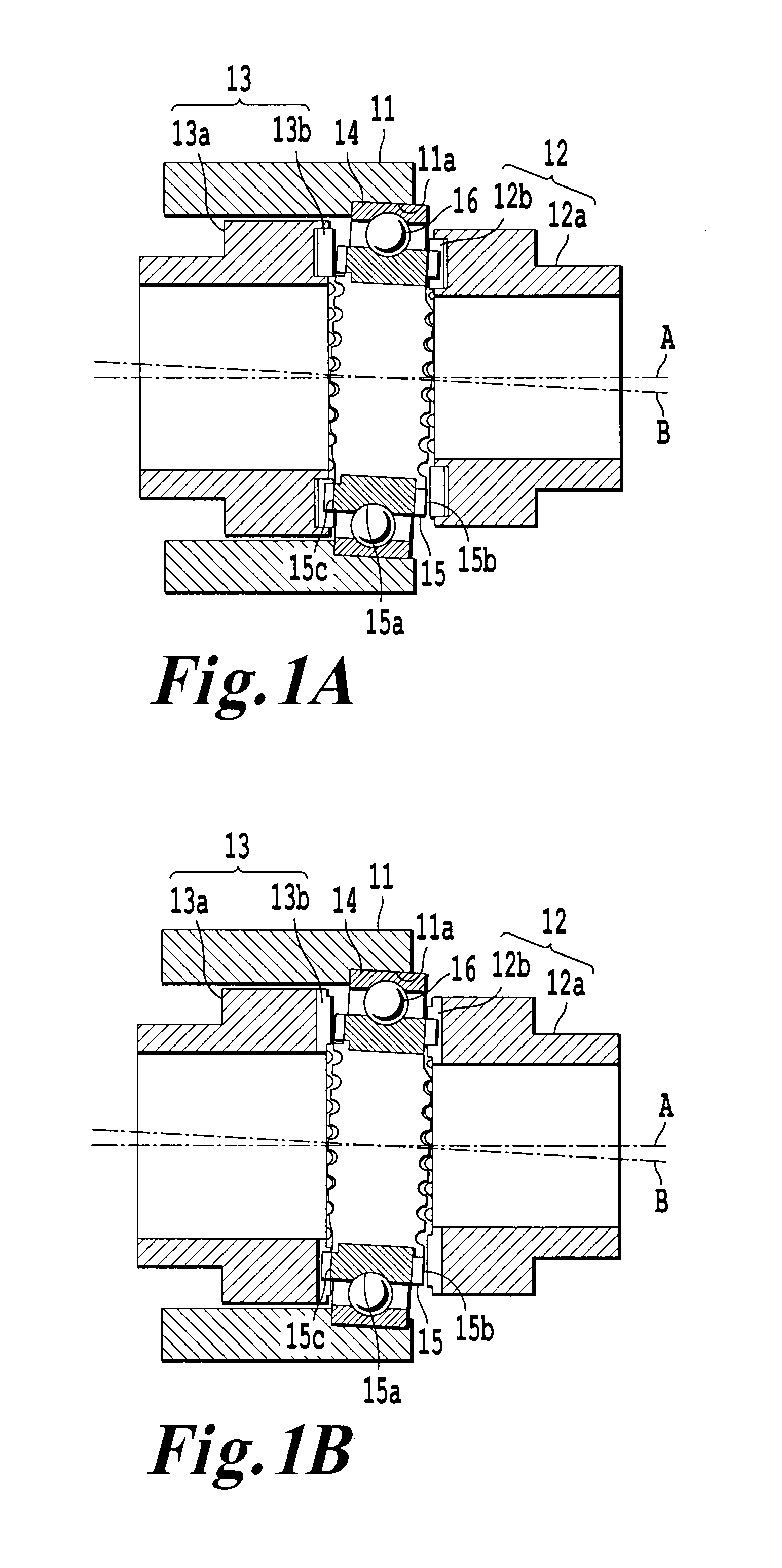
First Embodiment
Second Embodiment
Five-Axis Configuration (Three Linear Axes and Two Rotation Axes) (First Example of Omission of Fourth Rotation Axis)
Third Embodiment
Five-Axis Configuration (Three Linear Axes and Two Rotation Axes) (Second Example of Omission of Fourth Rotation Axis)
Fourth Embodiment
Four-Axis Configuration (Two Linear Axes and Two Rotation Axes) (Omission of Second Linear Axis and Fourth Rotation Axis)
Fifth Embodiment
Four-Axis Configuration (Two Linear Axes and Two Rotation Axes) (Omission of Third Linear Axis and Fourth Rotation Axis)
Sixth Embodiment
Four-Axis Configuration (Three Linear Axes and One Rotation Axis) and Toroidal Grinding Wheel
Seventh Embodiment
Others