CAMERA MODULE AND METHOD OF MANUFACTURING SAME
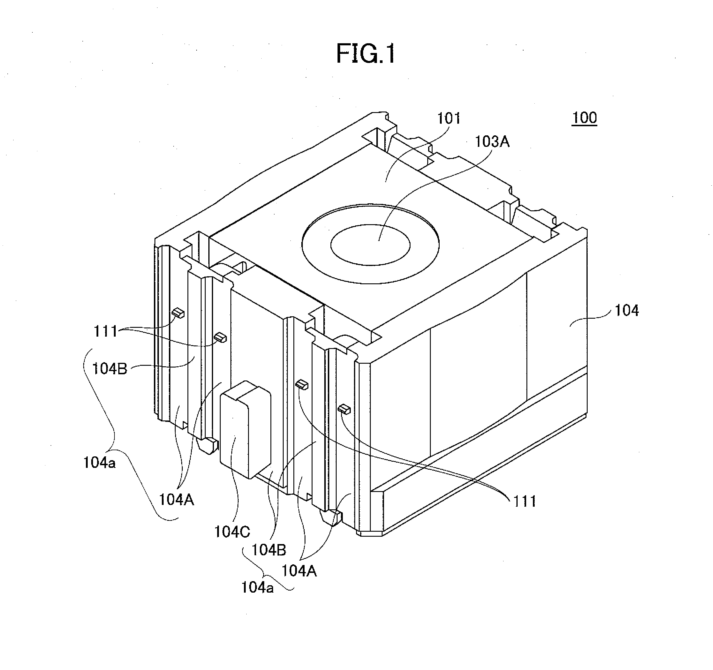
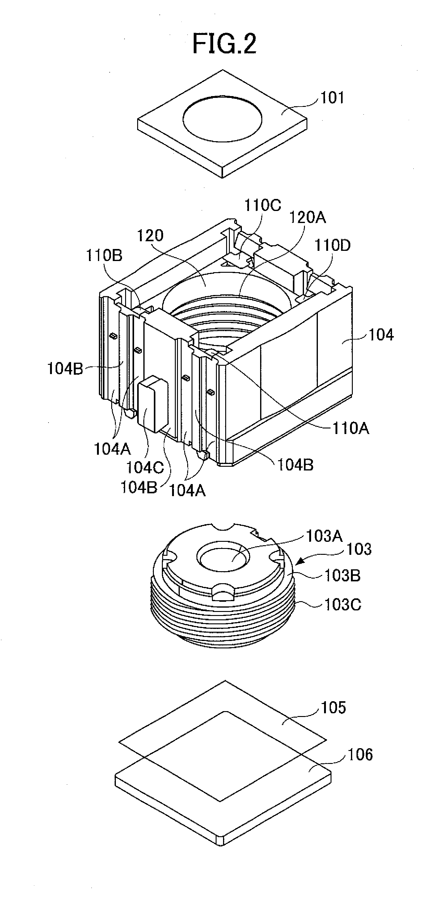
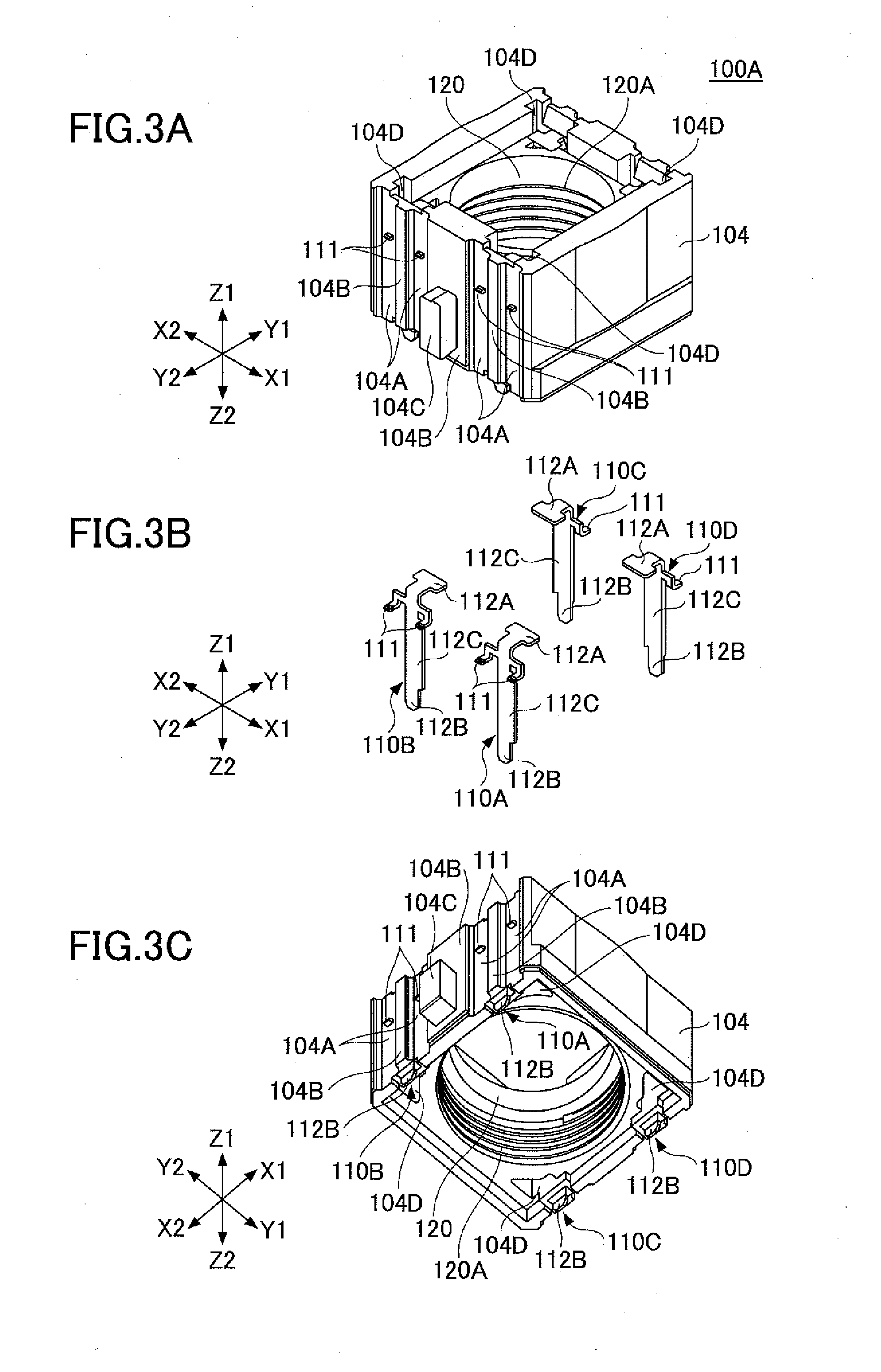
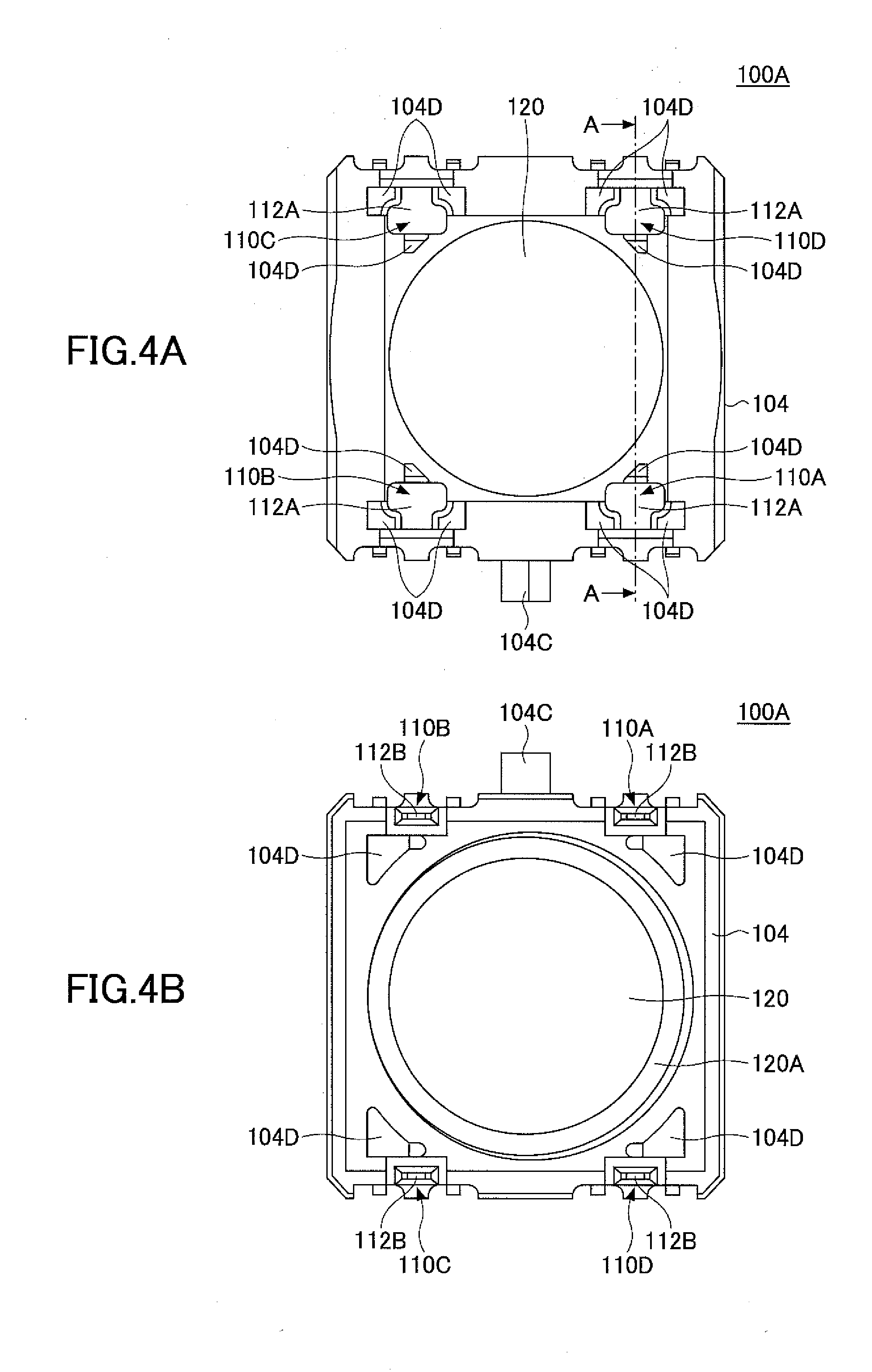
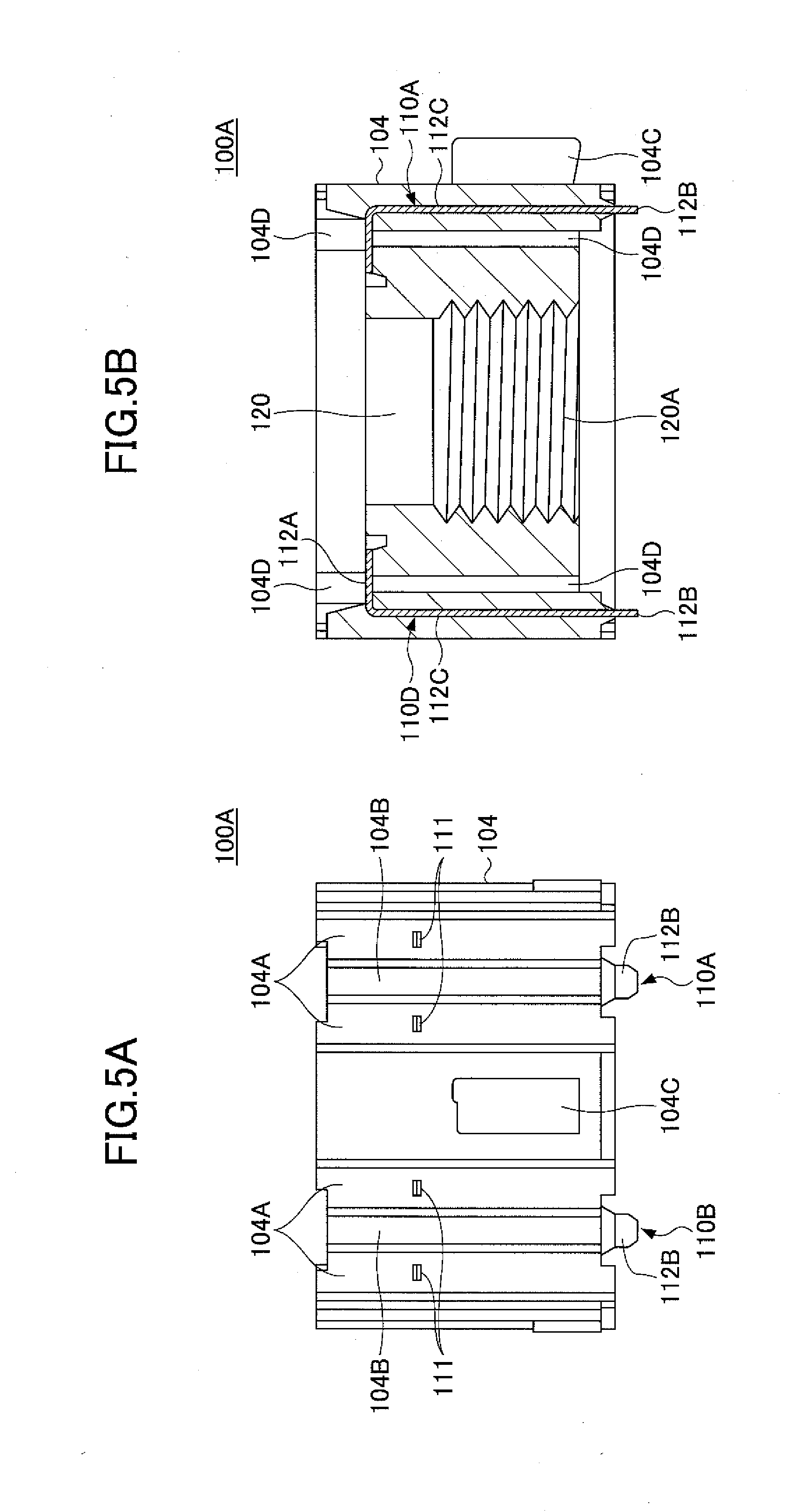
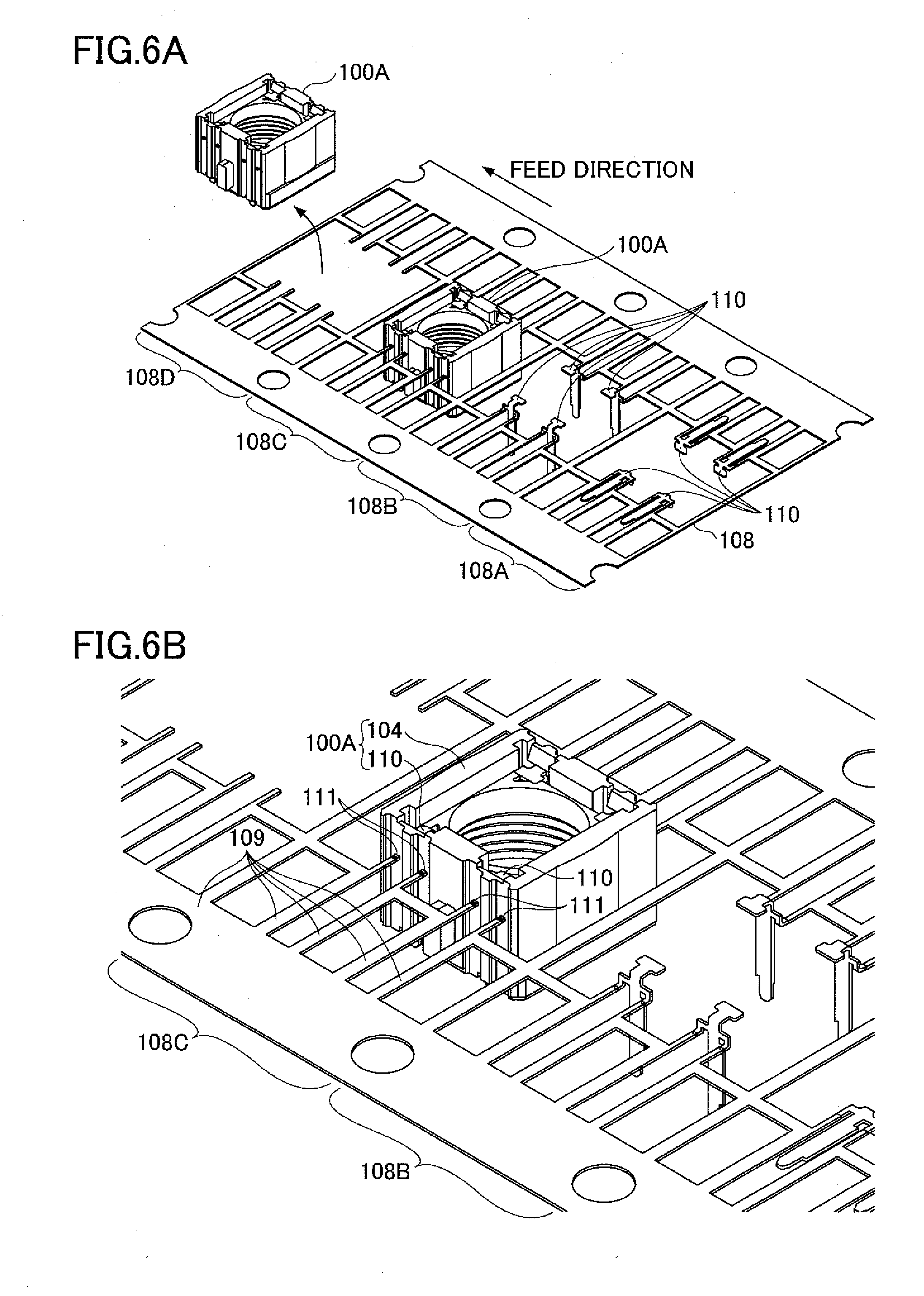
The present application is based upon and claims the benefit of priority of the prior Japanese Patent Application No. 2011-278927, filed on Dec. 20, 2011, the entire contents of which are incorporated herein by reference. 1. Field of the Invention The present invention relates to a camera and a method of manufacturing the same. 2. Description of the Related Art There is a conventional lens module where a substantially columnar magnet fixed to an electromechanical transducer is caused to vibrate with vibrations generated in the electromechanical transducer so that a movable body in point contact at two points or in surface contact with the magnet is driven to slide using the vibration of the magnet as a driving force, thereby causing a lens holder to which the movable body is attached to move along the directions of the optical axis of an optical lens. (For example, see Japanese Laid-Open Patent Application No. 2011-043526.) According to an aspect of the present invention, a camera module includes a plurality of terminals formed by performing press working on a metal plate; a holder formed with the terminals by insert molding, wherein the holder holds the terminals, a through hole is formed through the holder in a direction in which the terminals extend, and a screw part is formed on a sidewall of the through hole; a lens housed in the through hole by being screwed to the screw part; and a camera part attached to the holder on a rear side of the lens. According to an aspect of the present invention, a method of manufacturing a camera module includes forming a pressed substrate including a plurality of sets of terminals by performing press working on a metal plate; forming a holder by performing insert molding on each of the sets of the terminals so that the holder holds the terminals, wherein said forming the holder includes forming a through hole through the holder in a direction in which the terminals extend and forming a screw part on a sidewall of the through hole; and performing singulation of the holder on a holder basis. According to an aspect of the present invention, a camera module includes a plurality of metal terminals; a holder that is an insert-molded product including the terminals as inserts; a lens screwed into a through hole formed through the holder; and a camera part attached to the holder, wherein a light entrance surface of the camera part faces toward the lens. A description is given, with reference to the accompanying drawings, of one or more embodiments of the present invention, where a camera module and a method of manufacturing the camera module according to an aspect of the present invention may be applied. Referring to The automatic focus part 101 may be of a type that performs focusing the deformation of a piezoelectric element. The lens barrel 103 is a barrel-shaped component that houses a lens 103A inside a housing 103B. The housing 103B of the lens barrel 103 is made of resin, and a screw part 103C is formed on an exterior side surface of the housing 103B. That is, for example, the housing 103B is threaded on its exterior circumferential surface. The holder 104 is formed together with the terminals 110A through 110D by insert molding. That is, the holder 104 is an insert-molded product including the terminals 110A through 110D as inserts. The holder 104 is made of, for example, thermosetting resin. The terminals 110A through 110D extend downward (in a direction from the automatic focus part 101 to the image sensor 106) inside the holder 104. A wall part 104 The holder 104 includes a through hole 120 that houses the lens barrel 103. A screw part 120A is formed on an interior wall surface of the through hole 120. That is, for example, the holder 104 has an interior wall surface that defines the through hole 120, and the interior wall surface is threaded. The screw part 103C of the lens barrel 103 is screwed into the screw part 120A so that the lens barrel 103 is housed inside the through hole 120. The IR cut film 105 is provided between the lens barrel 103 and the image sensor 106 on the rear side (on the bottom side in Examples of the image sensor 106 include a charge coupled device (CCD) image sensor and a complementary metal oxide semiconductor (CMOS) image sensor. The number of pixels of the image sensor 106 may be so determined as to obtain a desired number of pixels, such as 8 million pixels or 12 million pixels. The terminal 110A through 110D are connected to corresponding terminals on the bottom (lower) surface of the automatic focus part 101 in Next, a description is given, with reference to In The module 100A illustrated in In the following, the terminals 110A through 110D may be collectively referred to as “terminals 110” in the case of making no distinction among the terminals 110A through 110D. Referring to An engagement part 104C is formed on the second wall part 104B on the Y2-side surface of the holder 104. The engagement part 104C serves to fix the camera module 100 to a board in the case of, for example, mounting the camera module 100 on the board. Further, through holes 104C are formed in the holder 104 as illustrated in Further, as illustrated in The first ends 112A are exposed at the top of the holder 104 in The second ends 112B are on the opposite side from the first ends 112A, and project from the holder 104 at its lower end as illustrated in The terminals 110A through 110D have the same structure. Accordingly, a description is given of the terminal 110A with respect to the details of the structure of the terminals 110A through 110D. The first end 112A of the terminal 110A extends in the Z1 direction from the intermediate part 112C, and is bent in the Y1 direction by press working. The second end 112B of the terminal 110A extends straight in the Z2 direction from the intermediate part 112C. The terminal 110A includes the cut part 111 that extends in the X1 and the X2 direction from the intermediate part 112C between the first end 112A and the second end 112B and then extends in the Y2 direction. The terminal 110A is manufactured by performing press working on a hoop material. The terminal 110A is formed by being cut off of (separated from) a carrier for singulation after forming the holder 104 by insert molding. The cut part 111 is a mark of the cutting of the terminal 110A off of the carrier at the time of singulation. Next, a description is given, with reference to Referring to Referring to Next, a description is given, with reference to As illustrated in Further, as illustrated in Next, a description is given, with reference to In the pressed plate 108 illustrated in Here, four regions that include respective sets of four terminals 110 of the pressed plate 108 illustrated in The regions 108A through 108D illustrated in In the region 108A, the four terminals 110A are punched out in a single region of the pressed plate 108 by press working, so that the first ends 112A, the second ends 112B, and the intermediate parts 112C ( In the region 108B, press working is performed to raise the intermediate parts 112C of the terminals 110 illustrated in the region 108A, so that the first ends 112A and the second ends 112B are raised. In the region 108C, insert molding is performed on the terminals 110 illustrated in the region 108B, so that the holder 104 (unitarily combined with the terminals 100) is formed. In this state, the module 100A is held by a carrier 109 of the pressed plate 108. Accordingly, by subjecting the module 100A in the region 108C shown enlarged in The cut parts 111 are portions of the terminals 110 that remain on the holder 104 as a result of cutting the carrier 109 of the pressed plate 108 at the time of performing singulation of the module 100A as illustrated in Here, processes at different stages are illustrated in the regions 108A through 108D, respectively. Each of press working (see the regions 108A and 108B), insert molding (see the region 108C), and singulation (see the region 108D) may be performed in one region after another as illustrated in the regions 108A through 108D while feeding the pressed plate 108 in the feed direction indicated by the arrow in Here, a description is given of the case where each of press working (see the regions 108A and 108B), insert molding (see the region 108C), and singulation (see the region 108D) is performed in one region after another as illustrated in the regions 108A through 108D while feeding the pressed plate 108 in the feed direction indicated by the arrow in Thus, according to the camera module 100 of one or more of the embodiments, the module 100A may be manufactured by forming the holder 104 by insert molding on the pressed plate 108 in which the multiple terminals 110 are formed by performing press working on a hoop material. Thereafter, the lens 103A (the lens barrel 103) may be attached to the screw part 120A of the through hole 120 of the holder 104 of the module 100A, and then, the IR cut film 105 and the image sensor 106 (a camera part) may be attached to the holder 104 so that the light entrance surface of the image sensor 106 faces toward the lens 103A (see The conventional module for a camera module is manufactured by, for example, forming holes for terminals in a holder and inserting terminals into the respective holes. Unfortunately, according to such a module manufacturing method, the manufacturing cost increases because of an increase in the number of manufacturing processes due to the assembly of the holder and the terminals. Further, the increase in the manufacturing cost makes it difficult to lower the price of the camera module, thus causing an increase in the cost of the camera module. Thus, the manufacturing cost of the conventional camera module is high. Further, there is also a problem in that the positioning accuracy of terminals is low. In contrast, according to the camera module 100 of one or more of the embodiments, the module 100A is manufactured by forming the holder 104 by performing insert molding on the pressed plate 108 in which the multiple terminals 110 are formed by performing press working on a hoop material. Accordingly, it is possible to manufacture the module 100A very easily. Therefore, using the module 100A makes it possible to reduce the manufacturing cost of the camera module 100 ( Thus, according to an aspect of the present invention, a camera module is provided that may be manufactured at low cost, and a method of manufacturing the camera module is provided. Further, since the module 100A is manufactured by forming the holder 104 by performing insert molding on the pressed plate 108 in which the multiple terminals 110 are formed by performing press working on a hoop material, the positioning accuracy of the terminals 110 is high. The terminals 110, which are connected to the automatic focus part 101 via an electrically conductive adhesive agent or the like, the positioning accuracy of the terminals 110 greatly affect the reliability and the yield of the camera module 100. Therefore, according to one or more of the embodiments, it is possible to provide the camera module 100 whose reliability and yield are greatly improved. All examples and conditional language provided herein are intended for pedagogical purposes of aiding the reader in understanding the invention and the concepts contributed by the inventors to further the art, and are not to be construed as limitations to such specifically recited examples and conditions, nor does the organization of such examples in the specification relate to a showing of the superiority or inferiority of the invention. Although one or more embodiments of the present invention have been described in detail, it should be understood that the various changes, substitutions, and alterations could be made hereto without departing from the spirit and scope of the invention. A camera module includes multiple terminals formed by performing press working on a metal plate; a holder formed with the terminals by insert molding, wherein the holder holds the terminals, a through hole is formed through the holder in a direction in which the terminals extend, and a screw part is formed on a sidewall of the through hole; a lens housed in the through hole by being screwed to the screw part; and a camera part attached to the holder on a rear side of the lens. 1. A camera module, comprising:
a plurality of terminals formed by performing press working on a metal plate; a holder formed with the terminals by insert molding, wherein the holder holds the terminals, a through hole is formed through the holder in a direction in which the terminals extend, and a screw part is formed on a sidewall of the through hole; a lens housed in the through hole by being screwed to the screw part; and a camera part attached to the holder on a rear side of the lens. 2. The camera module as claimed in 3. A method of manufacturing a camera module, comprising:
forming a pressed substrate including a plurality of sets of terminals by performing press working on a metal plate; forming a holder by performing insert molding on each of the sets of the terminals so that the holder holds the terminals, wherein said forming the holder includes forming a through hole through the holder in a direction in which the terminals extend and forming a screw part on a sidewall of the through hole; and performing singulation of the holder on a holder basis. 4. The method as claimed in the metal plate is a hoop material, and said forming the pressed substrate forms the sets of the terminals by performing the press working on the hoop material. 5. The method as claimed in 6. A camera module, comprising:
a plurality of metal terminals; a holder that is an insert-molded product including the terminals as inserts; a lens screwed into a through hole formed through the holder; and a camera part attached to the holder, wherein a light entrance surface of the camera part faces toward the lens. 7. The camera module as claimed in 8. The camera module as claimed in each of the terminals includes a portion that projects from an exterior surface of a wall part of the holder, and the wall part of the holder is depressed around the portion of each of the terminals that projects from the exterior surface of the wall part. CROSS-REFERENCE TO RELATED APPLICATION
BACKGROUND OF THE INVENTION
SUMMARY OF THE INVENTION
BRIEF DESCRIPTION OF THE DRAWINGS
DETAILED DESCRIPTION OF THE PREFERRED EMBODIMENTS