Apparatus for mixing fuel and air in a combustion system
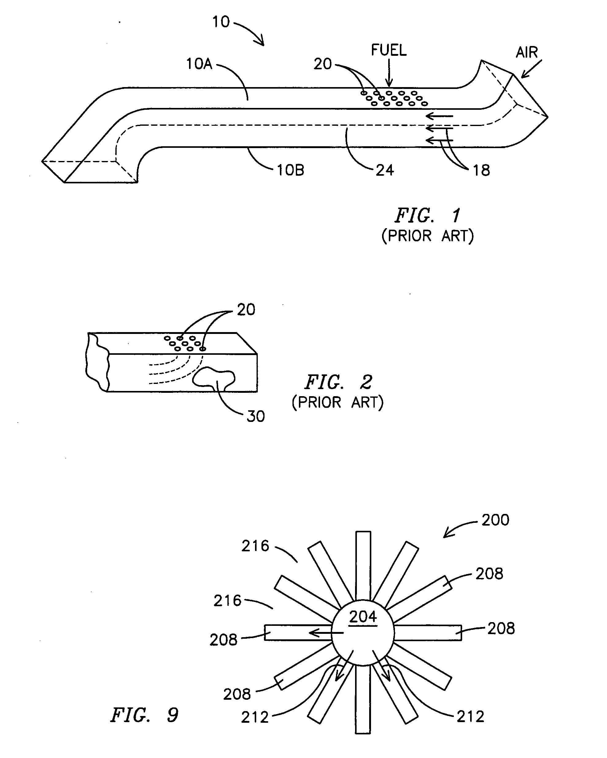
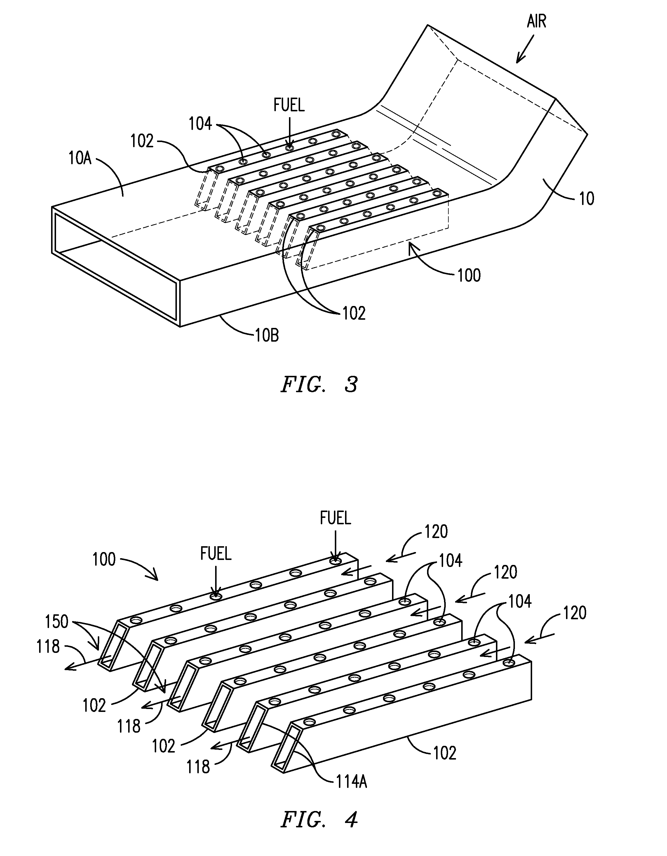
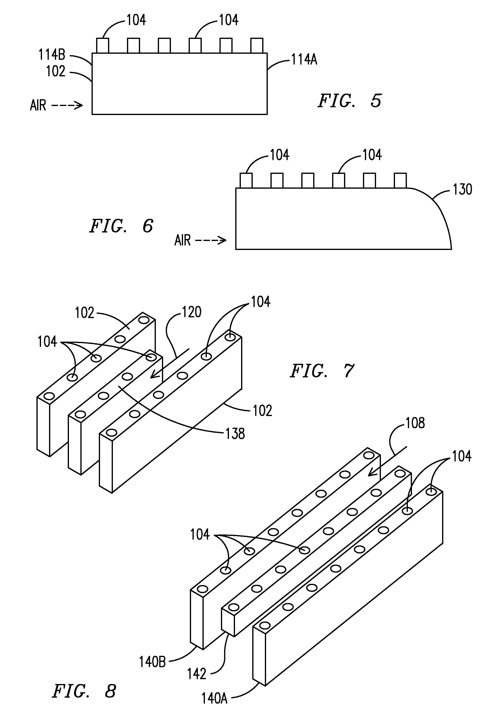
The invention was developed with U. S. Government support under contract number DE-FC-26-03NT41891. The Government therefore has certain rights in the invention. This invention is directed generally to combustion systems, and more particularly to mixing fuel and air for use in the combustion system. Gas (combustion) turbine engines generate power for a variety of applications including land-based electrical power generating plants. The turbines are designed to combust a broad range of hydrocarbon fuels, such as natural gas, kerosene, biomass gas, liquid natural gas, synthetic gas, etc. Gas turbines produce an exhaust stream containing a number of combustion byproducts, many of which are considered atmospheric pollutants. Increasingly stringent regulations have been imposed on the operation of gas turbine power plants in an effort to minimize the production of these gasses. Regulating production of the various forms of nitrogen oxides, collectively known as NOx, is of particular concern. It is known that gas turbine NOx emissions increase significantly as the combustion temperature rises. One method of limiting the NOx production employs the lean premixed concept where the fuel and combustion air are mixed prior to reaching the combustion zone at a relatively low fuel-to-air ratio. Limiting the peak combustion temperature reduces the NOx emissions. In this design the degree of mixing between the fuel and air is critical to the performance of the combustion system. Typically, a gas turbine engine comprises one or more injectors for injecting fuel into air (i.e., primary zone air) upstream of a combustor where the fuel burns. The fuel injectors of conventional turbine engines may be arranged in one of at least three different schemes. In a lean premix flame system, the fuel injectors are positioned to inject fuel into the air stream at an upstream location that is sufficiently separated from the flame zone to allow complete mixing of the fuel/air mixture prior to reaching and burning in the flame zone. Fuel injectors are configured in a diffusion flame system to simultaneously mix and burn the fuel and air. In a partially premixed system, the fuel injectors inject fuel upstream of the flame zone a sufficient distance to allow some of the air to mix with the fuel prior to reaching the flame zone. A partially premixed system is a combination of a lean premix flame system and a diffusion flame system. To avoid local hot spots that produce a high level of NOx emissions, a low-emission gas turbine combustion engine requires thorough mixing of the fuel and air streams prior to reaching the combustion zone. Preferred techniques for mixing the air and fuel streams are dependent on a momentum (mass multiplied by velocity) ratio of the two flow streams. With the current emphasis on alternative gas turbine fuels, it is desired that the gas turbine components function properly with different fuels. Fuel/air mixing apparatuses that rely on the momentum ratio to mix the fuels are satisfactory for only a narrow range of momentum ratios and therefore are limited to certain fuels. For a gas turbine combustor that can perform efficiently using a wide range of fuels, it is necessary to develop a method for fuel air mixing that is independent of the momentum ratio of the gas streams. One known prior art technique for mixing air and fuel, as illustrated in Excessive fuel penetration causes the fuel to strike an interior lower wall surface 10B of the manifold 10, creating a recirculation zone 30 as illustrated in If the fuel does not penetrate a sufficient distance into the air stream 18, the air/fuel mixture is stratified with a majority of the fuel proximate the upper surface 10A. In this case, the poorly mixed fuel results in a degradation of performance and increased NOx emissions. The momentum ratio of the fuel and air streams varies according to fuel type, fuel heating value and fuel density. To ensure proper air-fuel mixing, such as when the fuel supplied to the combustion turbine is changed, it is necessary to adjust the size and/or location of the fuel injection openings 20. For a combustion system that operates with many different types of fuel, it may be necessary to utilize more than one fuel manifold, each manifold having differently sized and/or located injection openings for use with a specific fuel type. As is known, current gas turbines must be capable of burning a wide variety of fuels including natural gas, liquid natural gas, syngas and hydrogen. Designing a gas turbine with multiple manifolds, each designed specifically for one fuel type is not a practical solution. Neither is it desired to remove and replace the fuel manifold whenever a different fuel type is to be burned. The problem of rapidly and thoroughly mixing the fuel and primary zone air has been addressed by the use of swirlers. Axial swirlers are disposed within the fuel injector or external the fuel injector along the fuel flow path to swirl the fuel flow and improve the air-fuel mixing process. A plurality of closely-spaced swirl cups downstream of the fuel injection point can enhance the air-fuel mixing process. Although these prior art techniques have helped to reduce NOx emissions, combustion performance can be further improved by further increasing the efficiency of mixing fuel and primary zone air prior to fuel combustion. Therefore, there is a need for an air-fuel mixer to further improve the process of mixing fuel and primary zone air. There is a further need for an efficient air-fuel mixer for use with various types of fuels, independent of the fuel momentum as it enters the air flow. According to one embodiment, the invention comprises a manifold for mixing fuel and air. The manifold further comprises an enclosure defining a first air flow channel through which air is directed, the enclosure bounded by an upper and a lower wall surface; fuel scoops extending from the upper surface into the air flow channel, each fuel scoop defining a fuel flow channel through which fuel is directed, each fuel scoop further defining a plurality of fuel receiving openings for receiving fuel, the fuel directed into the fuel flow channel and exiting the fuel scoops at a fuel outflow opening, adjacent ones of the fuel scoops defining a second air flow channel therebetween, wherein an air stream flows through the second air flow channel in a direction toward the fuel outflow openings and wherein the air stream creates a shear region proximate the fuel outflow openings, and wherein the air stream and the fuel stream mix in the shear region. The embodiments of the present invention can be more easily understood and the advantages and uses thereof more readily apparent when the following detailed description of the present invention is read in conjunction with the figures wherein: In accordance with common practice, the various described features are not drawn to scale, but are drawn to emphasize specific features relevant to the invention. Like reference characters denote like elements throughout the figures and text. While preferred embodiments of the present invention are described and illustrated herein, it will be obvious that such embodiments are provided by way of example only. Numerous variations, changes and substitutions will occur to those of skill in the art without departing from the invention. Accordingly, it is intended that the invention be limited only by the spirit and scope of the appended claims. A fuel manifold of an embodiment of the present invention produces acceptable fuel-air mixing for any fuel type, fuel density, fuel heating value and fuel/air momentum ratio, thereby overcoming limitations of prior art fuel manifolds. According to the present invention, as illustrated in A fuel stream flows through each scoop 102 and exits each scoop at a downstream open end 114A (see the side view of a single scoop 110 in The fuel shroud assembly 100 is disposed within the fuel manifold 10 to permit air flow between adjacent scoops as indicated by arrowheads 120 in The fuel shroud assembly 100 ensures proper penetration of the fuel into the manifold channel 12 independent of the fuel/air momentum ratio. The fuel manifold 10 of In one embodiment, the fuel shroud assembly 100 extends about ⅔ of the distance between the top surface 10A and the bottom surface 10B of the fuel manifold 10. In another embodiment the fuel shroud assembly 100 extends substantially the entire distance between the upper and lower surfaces 10A. In still another embodiment, adjacent scoops 102 are connected with sufficient unobstructed area between scoops to provide adequate air flow (arrowheads 120). In an embodiment of An embodiment of This is written description uses examples to disclose the invention, including the best mode, and also to enable any person skilled in the art to make and use the invention. The patentable scope of the invention is defined by the claims, and may include other examples that occur to those skilled in the art. Such other examples are intended to be within the scope of the claims if they have structural elements that do not differ from the literal language of the claims, or if they include equivalent structural elements with insubstantial differences from the literal languages of the claims. A fuel shroud assembly (100) into which fuel (118) is injected for mixing with an air stream (120) in a fuel manifold. The shroud assembly (100) comprises a plurality of parallel fuel scoops (102) each receiving the injected fuel (118). The fuel stream (118) flows through each scoop (102), exiting at an open scoop end (114A). The air stream (120) flows between scoops, creating a shear region proximate each scoop end (114A) where the fuel exits. The shear causes mixing of the air (120) and the fuel (118) streams, wherein the degree of mixing is not dependent on the momentum ratio of the air (120) or fuel (118) streams. 1. A fuel delivery apparatus for use within a fuel manifold of a gas turbine, the apparatus comprising:
laterally spaced apart fuel scoops, each fuel scoop having a rectangular cross section with the fuel scoops arranged in a parrallel configuration, and each defining a plurality of first openings on an external surface thereof for receiving fuel, each one of the fuel scoops directing fuel flow therethrough and the fuel exiting each fuel scoop at a second opening; adjacent ones of the fuel scoops defining an open channel therebetween, wherein an air stream flows only through the channel in a direction toward the second openings; and wherein the air stream creates a shear region proximate the second openings, and wherein the air stream and the fuel stream mix in the shear region. 2. The fuel delivery apparatus of 3. The fuel delivery apparatus of 4. (canceled) 5. (canceled) 6. The fuel delivery apparatus of 7. The fuel delivery apparatus of 8. A manifold for mixing fuel and air, the manifold comprising:
an enclosure defining a first air flow channel through which air is directed, the enclosure bounded by an upper and a lower wall surface; laterally spaced apart fuel scoops, each fuel scoop having a rectangular cross section with the fuel scoops arranged in a parallel configuration, each extending from the upper surface into the air flow channel, each fuel scoop defining a fuel flow channel through which fuel is directed, each fuel scoop further defining a plurality of fuel receiving openings on an external surface thereof for receiving fuel, the fuel directed into the fuel flow channel and exiting the fuel scoops at a fuel outflow opening; adjacent ones of the fuel scoops defining a second air flow channel therebetween, wherein an air stream flows only through the second air flow channel in a direction toward the fuel outflow openings; and wherein the air stream creates a shear region proximate the fuel outflow openings, and wherein the air stream and the fuel stream mix in the shear region. 9. The manifold of 10. The manifold of 11. (canceled) 12. (canceled) 13. The manifold of 14. The manifold of 15. A manifold for mixing fuel and air, the manifold comprising:
a first enclosure defining a first air flow channel through which air is directed; a second enclosure disposed axially within the first air flow channel, wherein fuel is directed through the second enclosure; fuel scoops extending radially from the second enclosure, wherein fuel is directed from the second enclosure through the fuel scoops and exits the fuel scoops at a fuel outflow opening; adjacent ones of the fuel scoops defining a second air flow channel therebetween, wherein an air stream of the first air flow channel flows only through the second air flow channel; and wherein the air stream creates a shear region proximate the fuel outflow openings, and wherein the air stream and the fuel mix in the shear region. 16. The manifold of 17. The manifold of 18. A fuel delivery apparatus for use within a fuel manifold of a gas turbine, the apparatus comprising:
laterally spaced apart fuel scoops, each defining a plurality of first openings for receiving fuel, each one of the fuel scoops directing fuel flow therethrough and the fuel exiting each fuel scoop at a second opening, wherein all fuel scoops extend a same distance into the fuel manifold. adjacent ones of the fuel scoops defining an open channel therebetween, wherein an air stream flows only through the channel in a direction toward the second openings; and wherein the air stream creates a shear region proximate the second openings, and wherein the air stream and the fuel stream mix in the shear region. 19. A fuel delivery apparatus for use within a fuel manifold of a gas turbine, the apparatus comprising:
laterally spaced apart fuel scoops, each defining a plurality of first openings for receiving fuel, each one of the fuel scoops directing fuel flow therethrough and the fuel exiting each fuel scoop at a second opening, wherein at least two of the fuel scoops extend a different distance into the fuel manifold; adjacent ones of the fuel scoops defining an open channel therebetween, wherein an air stream flows only through the channel in a direction toward the second openings; and wherein the air stream creates a shear region proximate the second openings, and wherein the air stream and the fuel stream mix in the shear region. 20. A manifold for mixing fuel and air, the manifold comprising:
an enclosure defining a first air flow channel through which air is directed, the enclosure bounded by an upper and a lower wall surface; laterally spaced apart fuel scoops extending from the upper surface into the air flow channel, each fuel scoop defining a fuel flow channel through which fuel is directed, each fuel scoop further defining a plurality of fuel receiving openings for receiving fuel, the fuel directed into the fuel flow channel and exiting the fuel scoops at a fuel outflow opening, wherein all fuel scoops extend a same distance into the first air flow channel; adjacent ones of the fuel scoops defining a second air flow channel therebetween, wherein an air stream flows only through the second air flow channel in a direction toward the fuel outflow openings; and wherein the air stream creates a shear region proximate the fuel outflow openings, and wherein the air stream and the fuel stream mix in the shear region 21. A manifold for mixing fuel and air, the manifold comprising:
an enclosure defining a first air flow channel through which air is directed, the enclosure bounded by an upper and a lower wall surface; laterally spaced apart fuel scoops extending from the upper surface into the air flow channel, each fuel scoop defining a fuel flow channel through which fuel is directed, each fuel scoop further defining a plurality of fuel receiving openings for receiving fuel, the fuel directed into the fuel flow channel and exiting the fuel scoops at a fuel outflow opening, wherein at least two of the fuel scoops extend a different distance into the first air flow channel; adjacent ones of the fuel scoops defining a second air flow channel therebetween, wherein an air stream flows only through the second air flow channel in a direction toward the fuel outflow openings; and wherein the air stream creates a shear region proximate the fuel outflow openings, and wherein the air stream and the fuel stream mix in the shear region.FIELD OF THE INVENTION
BACKGROUND OF THE INVENTION
BRIEF SUMMARY OF THE INVENTION
BRIEF DESCRIPTION OF THE DRAWINGS
DETAILED DESCRIPTION OF THE INVENTION