NETWORK TRAFFIC DISTRIBUTION
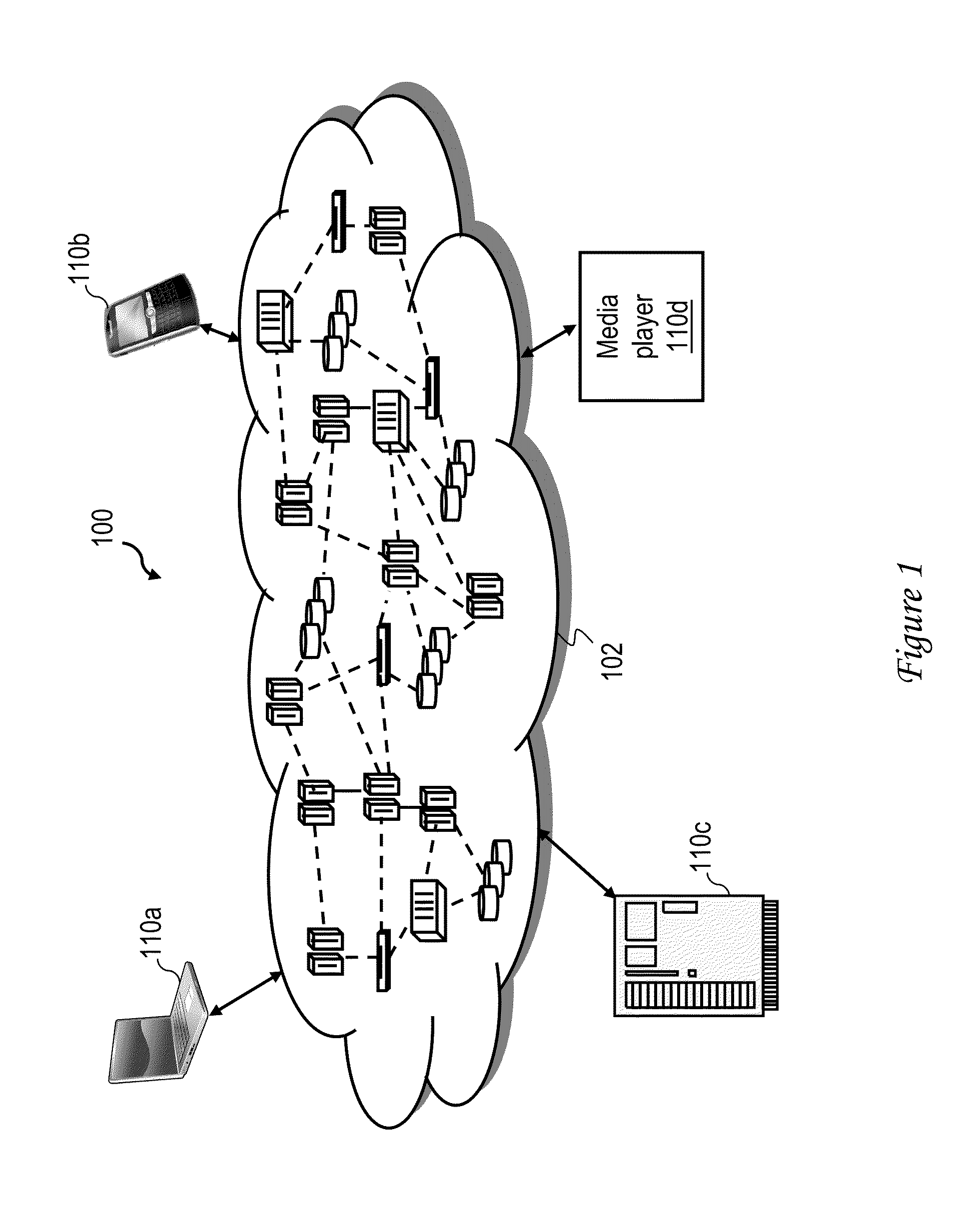
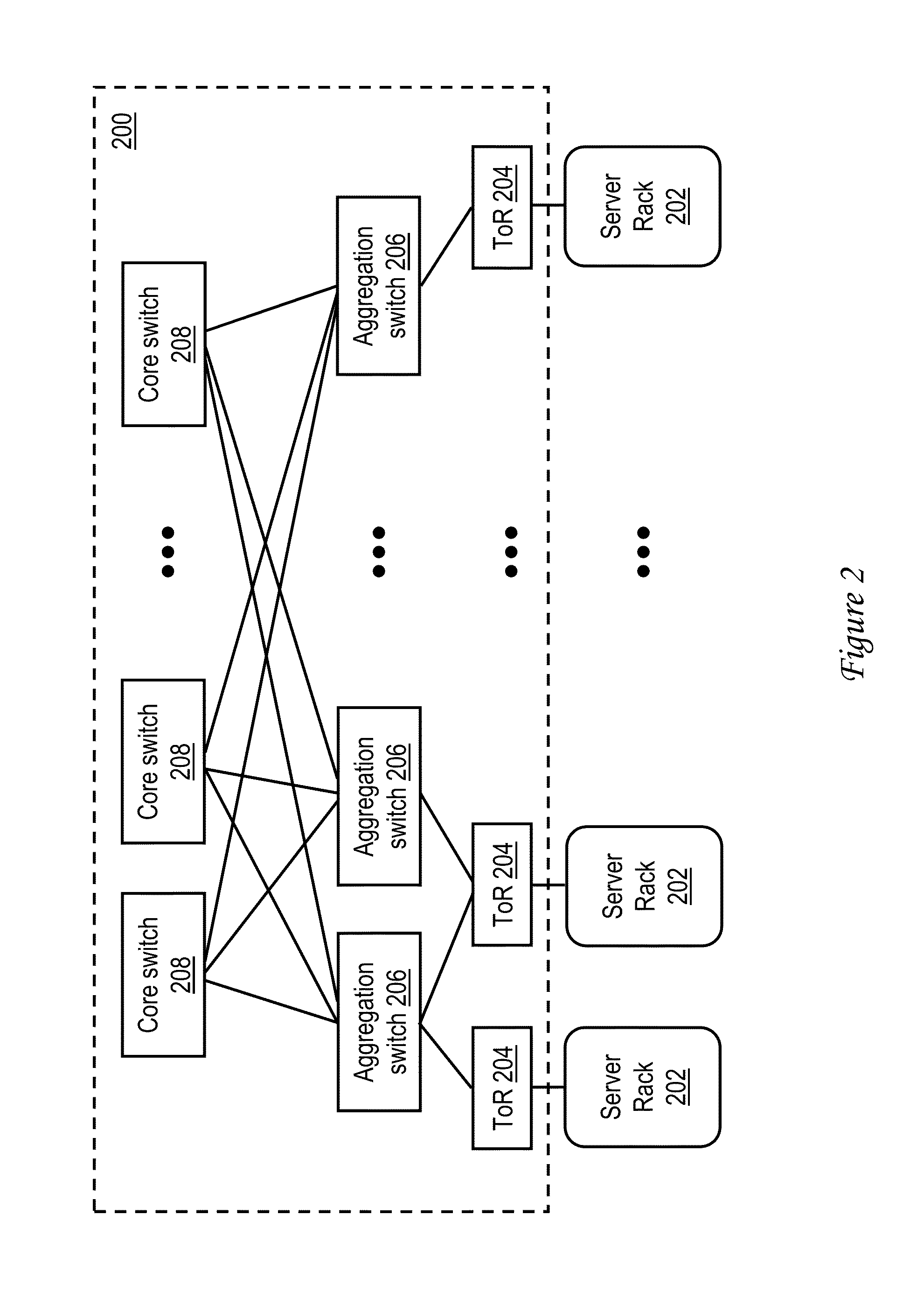
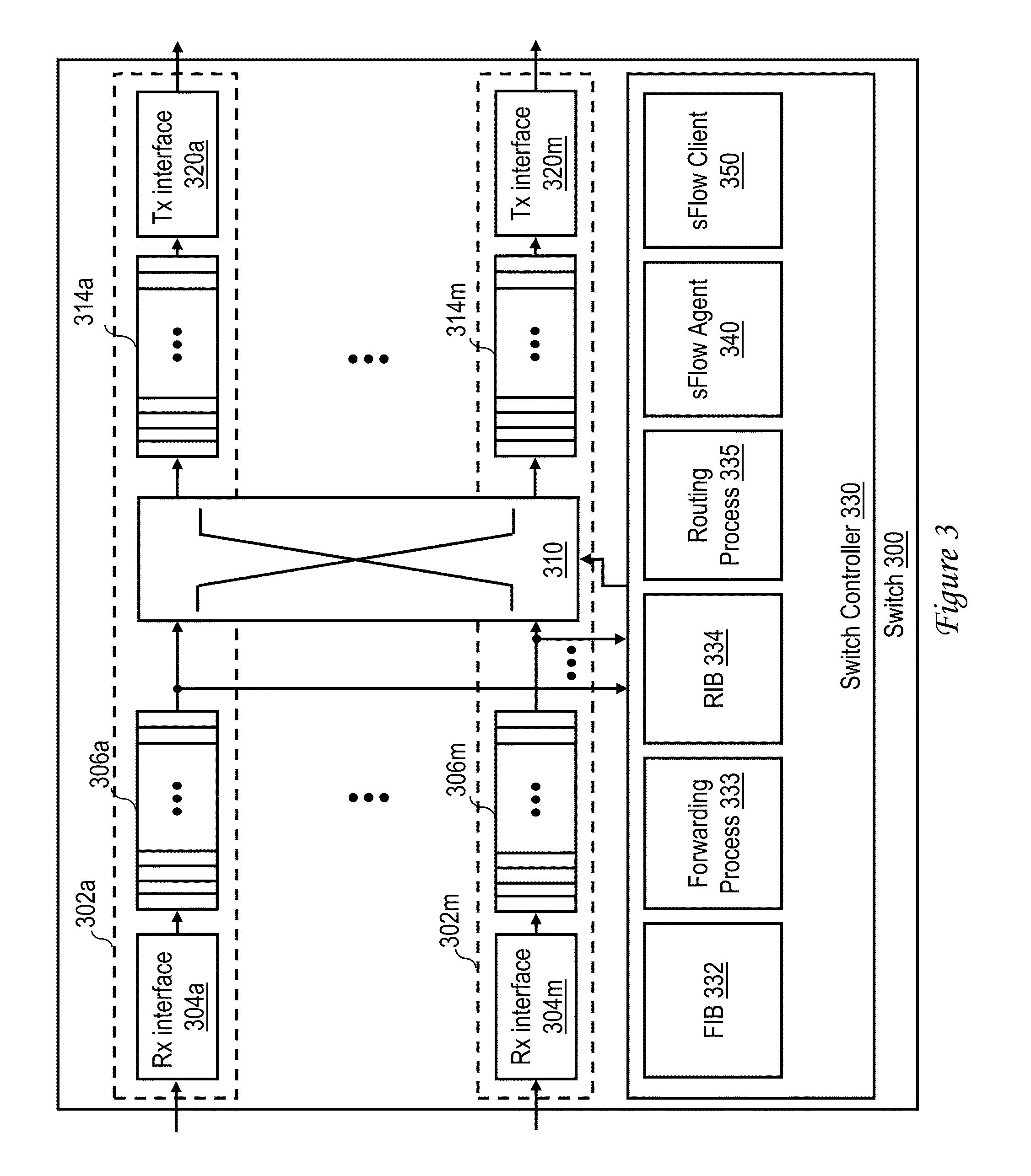
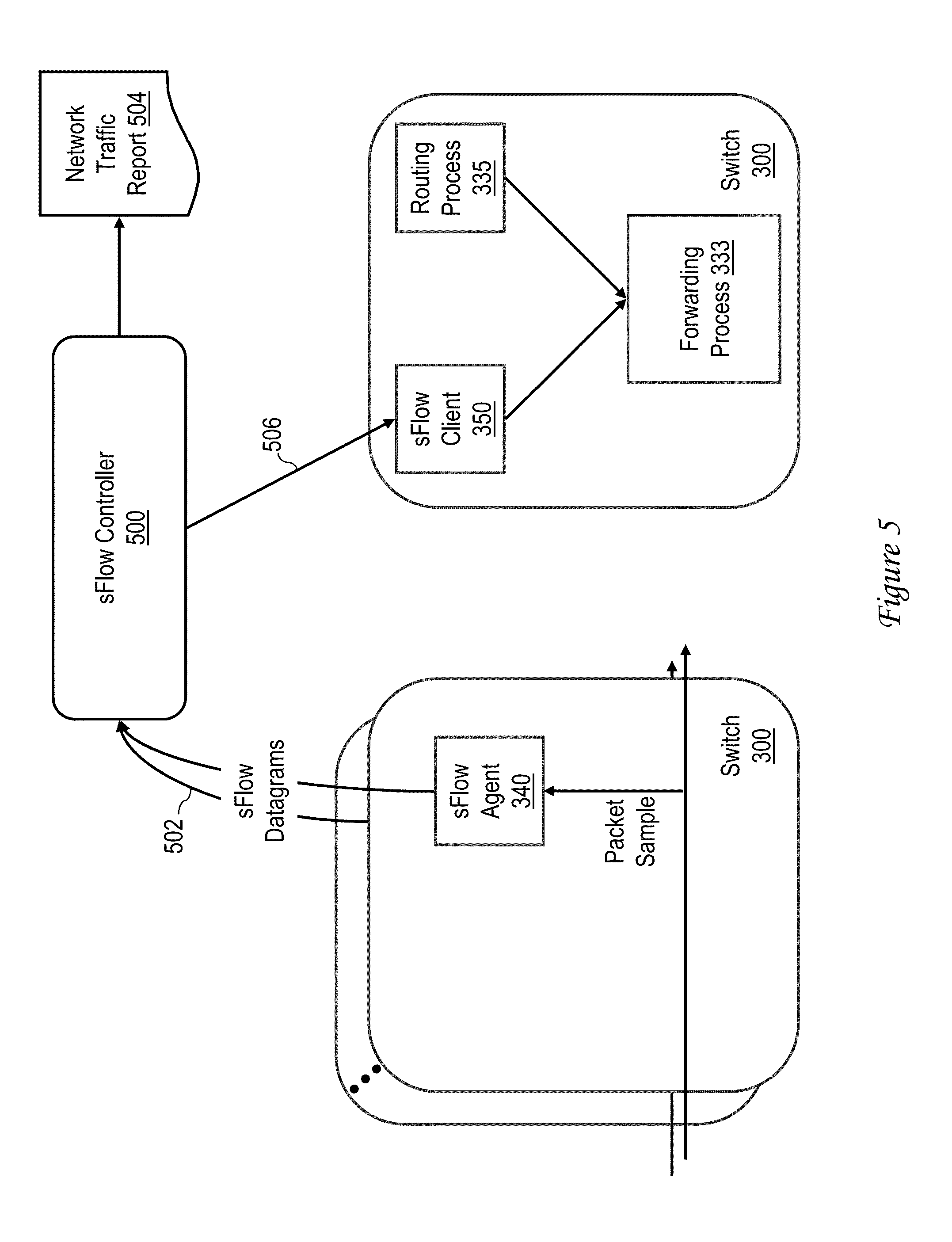
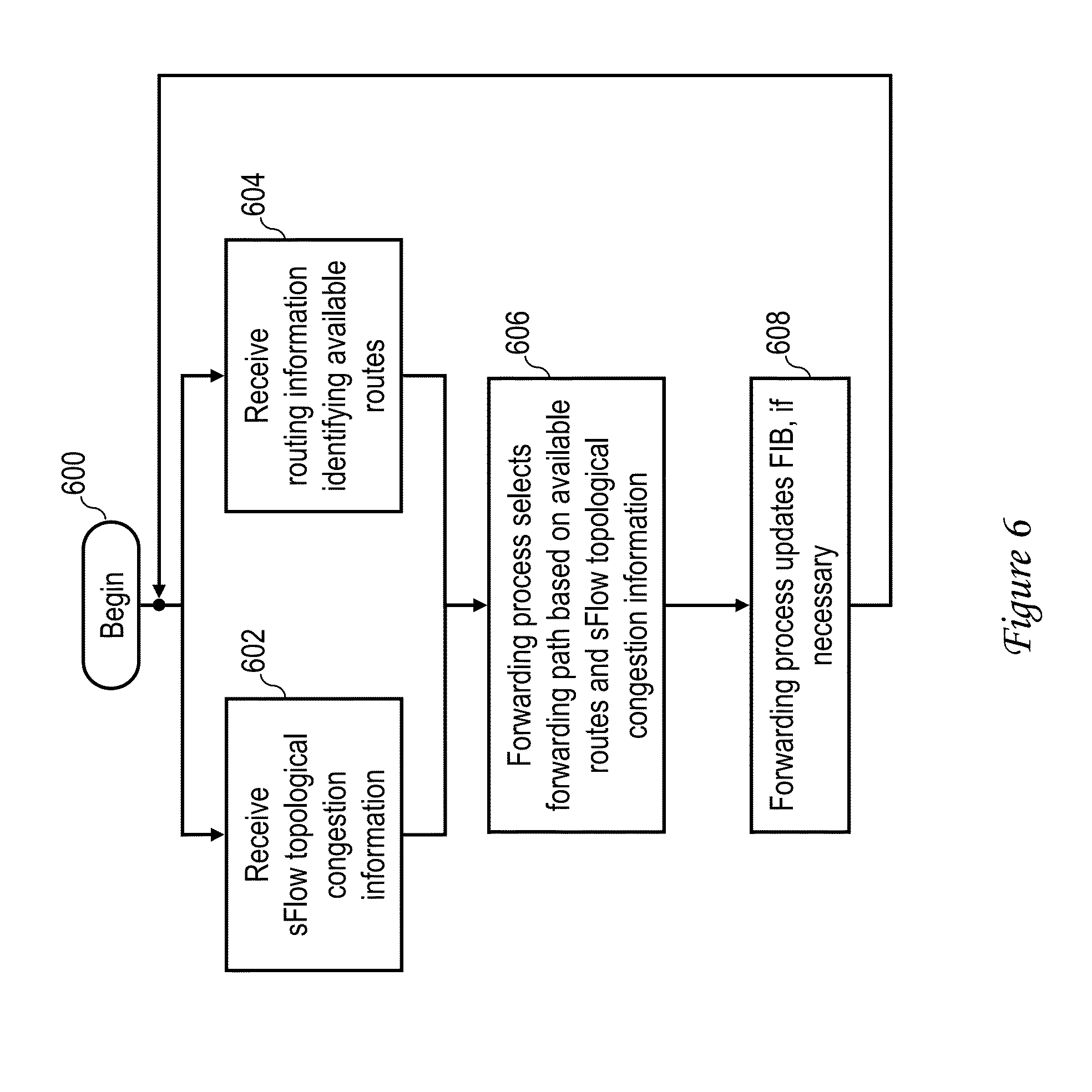
This application is a continuation of U.S. patent application Ser. No. 13/267,459 entitled “NETWORK TRAFFIC DISTRIBUTION,” filed on Oct. 6, 2011, the disclosure of which is incorporated herein by reference in its entirety for all purposes. 1. Technical Field The present disclosure relates in general to network communication and, in particular, to traffic distribution in packet switched networks. 2. Description of the Related Art As is known in the art, network communication is commonly premised on the well known seven layer Open Systems Interconnection (OSI) model, which defines the functions of various protocol layers while not specifying the layer protocols themselves. The seven layers, sometimes referred to herein as Layer 7 through Layer 1, are the application, presentation, session, transport, network, data link, and physical layers, respectively. At a source station, data communication begins when data is received from a source process at the top (application) layer of the stack of functions. The data is sequentially formatted at each successively lower layer of the stack until a data frame of bits is obtained at the data link layer. Finally, at the physical layer, the data is transmitted in the form of electromagnetic signals toward a destination station via a network link. When received at the destination station, the transmitted data is passed up a corresponding stack of functions in the reverse order in which the data was processed at the source station, thus supplying the information to a receiving process at the destination station. The principle of layered protocols, such as those supported by the OSI model, is that, while data traverses the model layers vertically, the layers at the source and destination stations interact in a peer-to-peer (i.e., Layer N to Layer N) manner, and the functions of each individual layer are performed without affecting the interface between the function of the individual layer and the protocol layers immediately above and below it. To achieve this effect, each layer of the protocol stack in the source station typically adds information (in the form of an encapsulated header) to the data generated by the sending process as the data descends the stack. At the destination station, these encapsulated headers are stripped off one-by-one as the data propagates up the layers of the stack until the decapsulated data is delivered to the receiving process. The physical network coupling the source and destination stations may include any number of network nodes interconnected by one or more wired or wireless network links. The network nodes commonly include hosts (e.g., server computers, client computers, mobile devices, etc.) that produce and consume network traffic, switches, and routers. Conventional network switches interconnect different network segments and process and forward data at the data link layer (Layer 2) of the OSI model. Switches typically provide at least basic bridge functions, including filtering data traffic by Layer 2 Media Access Control (MAC) address, learning the source MAC addresses of frames, and forwarding frames based upon destination MAC addresses. Routers, which interconnect different networks at the network (Layer 3) of the OSI model, typically implement network services such as route processing, path determination and path switching. A large network typically includes a large number of switches, which operate somewhat independently. Switches within the flow path of network data traffic include an ingress switch that receives incoming data packets and an egress switch that sends outgoing data packets, and frequently further include one or more intermediate switches coupled between the ingress and egress switches. In such a network, a switch is said to be congested when the rate at which data traffic ingresses at the switch exceeds the rate at which data traffic egresses at the switch. In conventional networks, when a switch in a data flow path is congested with data traffic, the congested switch may apply “back pressure” by transmitting one or more congestion management messages, such as a priority-based flow control (PFC) or congestion notification (CN) message, requesting other switches in the network that are transmitting data traffic to the congested switch to reduce or to halt data traffic to the congested switch. Conventional congestion management message may specify a backoff time period during which data traffic is reduced or halted, where the backoff time may be determined upon the extent of congestion experienced by the congested switch. Conventional congestion management messages may not provide satisfactory management of network traffic, however. While serving to temporarily reduce the transmission rate of some network nodes, conventional congestion management does nothing to address persistent long term congestion on switching ports, which can arise, for example, in cases in which different high-traffic source-destination address tuples hash to the same network path. In at least one embodiment, a switch for a switching network includes a plurality of ports for communicating data traffic and a switch controller that controls switching between the plurality of ports. The switch controller selects a forwarding path for the data traffic based on at least topological congestion information for the switching network. In a preferred embodiment, the topological congestion information includes sFlow topological congestion information and the switch controller includes an sFlow client that receives the sFlow topological congestion information from an sFlow controller in the switching network. With reference now to the figures and with particular reference to Referring now to Switching network 200 has at a lowest tier a plurality of top-of-rack (ToR) switches 204 each mounted on a respective one of server racks 202. Switching network 200 additionally includes a middle tier of aggregation switches 206, each of which is coupled to, and aggregates data traffic of one or more ToRs 204. Switching network 200 finally includes at an upper tier a plurality of core switches 208. In the depicted embodiment, aggregation switches 206 and core switches 208 are coupled in a full mesh topology in which each core switch 208 is coupled to each of aggregation switches 206. In a switching network 200 such as that illustrated, any of switches 204, 206 and 208 may become congested as one or more other switches of switching network 200 transmit data traffic at a rate greater than that switch 202 is itself able to forward that data traffic towards its destination(s). In many switching networks 200, congestion in some intermediate node (a switch 208 or 206) prevents data packets from being delivered to a final egress switch 204 even if there exists some alternate path to that egress switch 204. For example, a particular core switch 208 may become congested as multiple aggregation switches 206 concentrate egress data traffic at the same core switch 208, for example, due to multiple frequently referenced source-destination address tuples hashing to the same network path. With reference now to Switch 300 additionally includes a switch fabric 310, such as a crossbar or shared memory switch fabric, which is operable to intelligently switch data frames from any of ingress queues 306 In order to intelligently switch data frames, switch controller 330 builds and maintains one or more data plane data structures, for example, a Layer 2 forwarding information base (FIB) 332 and a Layer 3 routing information base (RIB) 334, which can be implemented, for example, as tables in content-addressable memory (CAM). In some embodiments, the contents of FIB 332 can be preconfigured, for example, by utilizing a management interface to specify particular egress ports 302 for particular traffic classifications (e.g., MAC addresses, traffic types, ingress ports, etc.) of traffic. Switch controller 330 can alternatively or additionally build FIB 332 in an automated manner by learning from observed data frames an association between ports 302 and destination MAC addresses specified by the data frames and recording the learned associations in FIB 332. A forwarding process 333 in switch controller 330 thereafter controls switch fabric 310 to switch data frames in accordance with the associations recorded in FIB 332. RIB 334, if present, can similarly be preconfigured or dynamically configured with routes associated with Layer 3 addresses, which are utilized by routing process 335 to route data packets. For example, in a embodiment in which switch 300 is a TRILL switch implemented in a TRILL network, RIB 334 is preferably preconfigured with a predetermined route through switching network 200 among multiple possible equal cost paths for each destination address. In other embodiments, dynamic routing algorithms, such as OSPF (Open Shortest Path First) or the like, can be utilized to dynamically select (and update RIB 334 with) a route for a flow of data traffic based on Layer 3 address and/or other criteria. Switch controller 330 additionally includes an sFlow agent 340 that monitors operation of switch 300 in accordance with the sFlow protocol specifications promulgated by the sFlow.org consortium. In general, sFlow agent 340 captures a random sampling of (1 of N) packets transiting switch 300 and a time-based sampling of counters within interfaces 304 and 320. Sflow agent 340 reports the collected information to a central sFlow controller 500 (see, e.g., Switch controller 330 additionally includes an sFlow client 350 that, as discussed in greater detail below, receives sFlow information from the sFlow controller of switching network 200 and supplies the information to forwarding process 333 to optimize the distribution of data traffic in switching network 200. As noted above, any of switches 202 may be implemented as a virtual switch by program code executed on a physical host platform. For example, With reference now to In accordance with the present disclosure, the capabilities of sFlow controller 500 are extended to include the distribution of relevant topological congestion information 506 to one or more (and possibly all of) switches 300 in switching network 200. Topological congestion information 506, which identifies one or more forwarding paths of the recipient switch 300 that are experiencing higher congestion relative to other forwarding paths of the receiving switch 300, is received by the sFlow client 350 of the recipient switch 300, which in turn informs forwarding process 333 of the recipient switch 300. In response, forwarding process 333 of the recipient switch 300 selects a forwarding path for its data traffic among multiple equal cost paths (i.e., ECMP paths) based on available path information from the routing process 335 and the topological congestion information provided by sFlow client 350. Forwarding process 350 may further update FIB 332 with an entry associating the selected forwarding path and the Layer 2 destination address of the data traffic. Referring now to The process begins at block 600 and then proceeds to block 602 and 604, which illustrate forwarding process 333 asynchronously receiving sFlow topological congestion information (e.g., from sFlow client 350) and routing information (e.g., from routing process 335). Forwarding process 333 then selects a forwarding path for its data traffic from among multiple network paths based upon the available paths indicated by the routing information and the sFlow topological congestion information (block 606). At block 606, forwarding process 333 preferably selects the forwarding path in order to reduce network congestion along the forwarding path(s) indicated by the sFlow topological congestion information provided by sFlow controller 500 and sFlow client 350. If needed, forwarding process 333 updates FIB 332 with an entry associating the selected forwarding path and the Layer 2 destination address of the data traffic (block 608). Thereafter the process returns to block 602 and 604, which have been described. As has been described, in at least one embodiment a switch for a switching network includes a plurality of ports for communicating data traffic and a switch controller that controls switching between the plurality of ports. The switch controller selects a forwarding path for the data traffic based on at least topological congestion information for the switching network. In a preferred embodiment, the topological congestion information includes sFlow topological congestion information and the switch controller includes an sFlow client that receives the sFlow topological congestion information from an sFlow controller in the switching network. While the present invention has been particularly shown as described with reference to one or more preferred embodiments, it will be understood by those skilled in the art that various changes in form and detail may be made therein without departing from the spirit and scope of the invention. For example, although aspects have been described with respect to one or more machines (e.g., hosts and/or network switches) executing program code (e.g., software, firmware or a combination thereof) that direct the functions described herein, it should be understood that embodiments may alternatively be implemented as a program product including a tangible machine-readable storage medium or storage device (e.g., an optical storage medium, memory storage medium, disk storage medium, etc.) storing program code that can be processed by a machine to cause the machine to perform one or more of the described functions. A switch for a switching network includes a plurality of ports for communicating data traffic and a switch controller that controls switching between the plurality of ports. The switch controller selects a forwarding path for the data traffic based on at least topological congestion information for the switching network. In a preferred embodiment, the topological congestion information includes sFlow topological congestion information and the switch controller includes an sFlow client that receives the sFlow topological congestion information from an sFlow controller in the switching network. 1. A method of operating a switch in a switching network, the method comprising:
receiving data traffic; receiving topological congestion information for the switching network; and selecting a forwarding path for the data traffic among multiple possible forwarding paths reachable from the switch based on at least topological congestion information for the switching network. 2. The method of the topological congestion information includes sFlow topological congestion information; and the method further includes an sFlow client on the switch receiving the sFlow topological congestion information from an sFlow controller in the switching network. 3. The method of 4. The method of 5. The method of BACKGROUND OF THE INVENTION
SUMMARY OF THE INVENTION
BRIEF DESCRIPTION OF THE DRAWINGS
DETAILED DESCRIPTION OF ILLUSTRATIVE EMBODIMENT