Knee Airbag Module
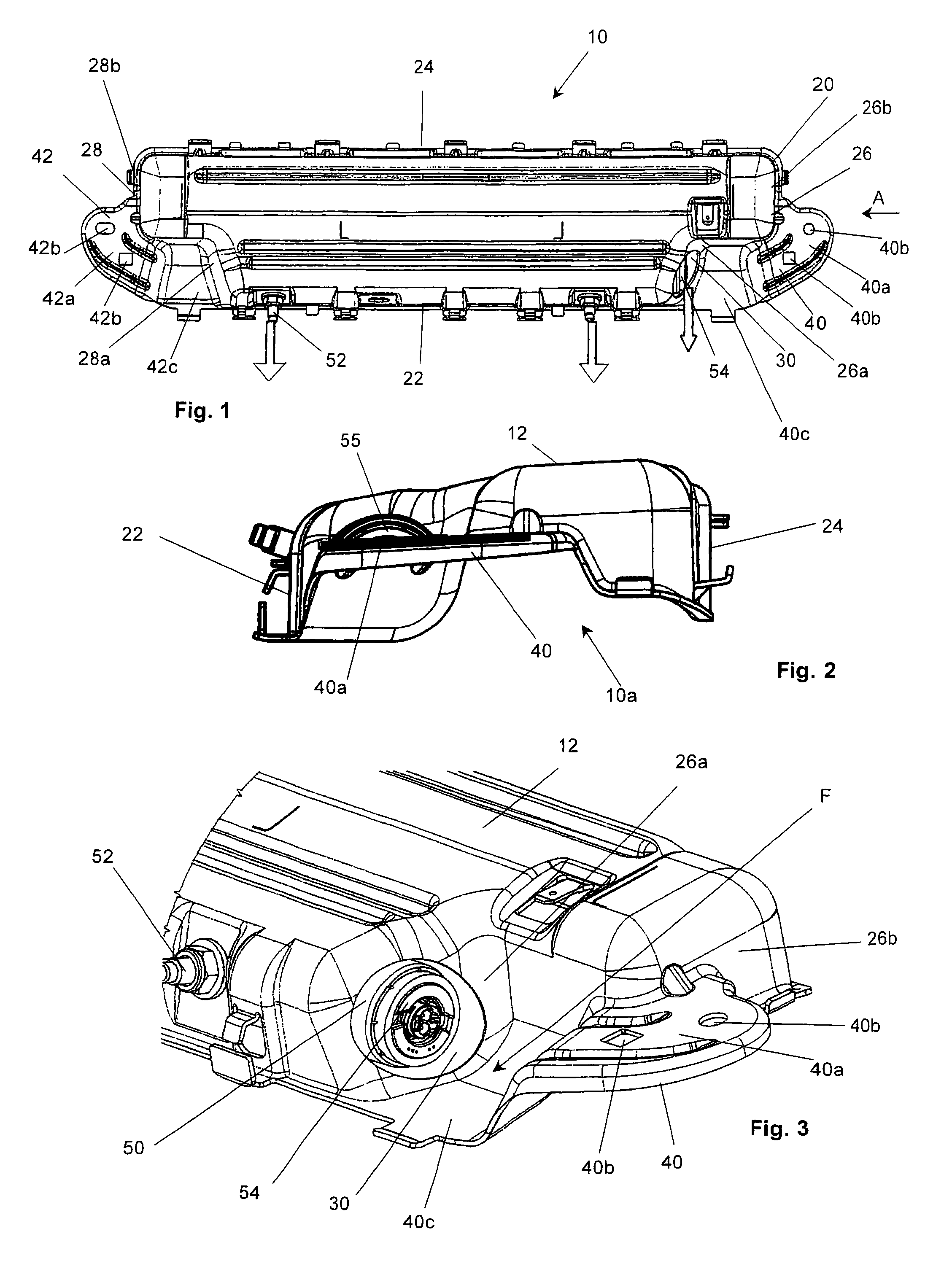
This application claims priority to German Patent Application No. 20 2011 002 778.3, filed Feb. 16, 2011 and PCT/EP2011/002257, filed May 6, 2011. The invention relates to a knee airbag module for a motor vehicle. Knee airbag modules are becoming increasingly common in modern automobile construction. Such a knee airbag module consists basically of a housing, an airbag folded into the housing, and a gas generator connected to the housing. The airbag, which can be inflated by the gas generator, helps to prevent the knee and shin region of the protected occupant from striking against the relatively hard instrument panel, and further has the task of preventing the forward displacement of the occupant's pelvis in a head-on collision. This is especially important for unbelted occupants. There are two basic concepts for arranging such a knee airbag module in a vehicle. In the first concept, the housing of the knee airbag module is around knee height of the protected occupant, and the opening of the housing points in the direction of the knee or shin. The airbag then basically expands in the direction of the occupant. In a second concept (low mount), the housing is in a lower section of the dashboard or in an adjacent area of the footroom cover. In this case, the housing, which can be made relatively flat, basically horizontal, means that the outlet opening of the housing extends basically horizontally. In this case the fully unfolded knee airbag generally has a “banana-shaped” cross section. A generic “low mount” knee airbag module is described in De 10 2009 005 993 A1. The knee airbag module of that design has a housing with an upper wall and with a peripheral side wall. The gas generator is arranged nearly entirely within the housing and extends in the proximity of the front section of the peripheral side wall and parallel to the section. A fastening flange extends from each of the two opposite side sections of the side wall. The two fastening flanges serve to fasten the knee airbag module to a vehicle-secured structural component, for which purpose the flanges each have a fastening section, the surfaces of which face toward the vehicle are designated hereinafter as fastening surfaces. The two fastening surfaces are hereby relatively long, with the result that the corresponding vehicle-secured structural components must also have accordingly long fastening surfaces. On the basis of the fact that frequently there is only very little mounting room available, providing the accordingly long fastening surfaces in the vehicle can in many cases be problematic. Proceeding therefrom, the task of the present invention is therefore to further develop a general knee airbag module such that only fastening surfaces of shorter length are required. Since the expanding airbag transfers forces nearly exclusively to the gas generator, and the gas generator again directs forces into the housing, lever forces are generated when the fastening surfaces of the fastening flanges are spaced apart from the gas generator axis. According to the invention, the fastening surfaces of the fastening flanges therefore are arranged close to the gas generator axis, namely in such a way that the fastening surfaces of the fastening sections overlap the radial extent of the gas generator at least in a vertical projection direction with reference to the mounted state. In this way, the acting lever forces are strongly reduced, with the result that the fastening surfaces of the fastening flanges and thus also the corresponding fastening mating surfaces of a vehicle-secured structural component need to be only relatively short. The length of the fastening surfaces of the fastening flanges relates here to the longitudinal direction of the vehicle. However, since at least one end of the gas generator must be accessible from outside of the housing, and preferably projects from the housing at least in part through an opening, it is necessary that at least the fastening section of the fastening flange, which is adjacent to the corresponding opening in the peripheral side wall, is spaced apart from the facing end of the gas generator. In a first preferred embodiment, the fastening surface overlaps directly with the radial extent of the gas generator. That means that if the gas generator were extended in the axial direction, the gas generator would strike the fastening surface. In this case, there must be a free space between the fastening section and the gas generator. In a second preferred exemplary embodiment, the fastening surface lies substantially under the gas generator. The present invention further has the task of simplifying the installation of the gas generator in the housing. The actual fastening of the gas generator and housing is by means of bolts, which extend radially from the gas generator through holes in the housing wall. But since, as already mentioned, it is desirable that at least one section of one end of the gas generator extend through an opening in a side section of the peripheral side wall, it is necessary to mount the gas generator into the housing with a type of tipping motion. Such an installation motion could be automated only at very great expense, and requires a very high level of dexterity of the executing installer, which in turn means that the installation is relatively time-consuming. In order to avoid the above referenced tipping motion during installation, according to the invention at least the region of the side wall section in which the opening is arranged runs obliquely to the gas generator axis. “Obliquely” here is understood to mean any angle which lies between 0° and 90°. Preferably the angle is between 40° and 80°; more preferably between 50° and 70°. In this way, the gas generator can be installed in a simple linear motion, and despite this the requirement can be fulfilled that at least one part of the end of the gas generator, which holds the igniter, projects from the housing. The arrangement according to the invention of the fastening flanges and the embodiment of the opening according to the invention can be very well combined, so that generally an airbag module can be made available which on the one hand can be easily assembled, and which on the other hand requires only relatively small fastening mating surfaces in the vehicle, which thus contributes generally to economization. The exemplary embodiments of the invention are described in more detail below with reference to the attached figures. In the figures, It can be seen in particular from At the point where the front regions 26 As can likewise be seen from The advantage of this arrangement of the fastening section 40 Basically, the fastening section 42 The main difference from the first exemplary embodiment is here, that the position of the fastening sections 40 One can see that in both exemplary embodiments, free access to the end 54 of the gas generator 50 is achieved on the one hand through the obliquity of the corresponding front regions 26 While the above description constitutes the preferred embodiment of the present invention, it will be appreciated that the invention is susceptible to modification, variation and change without departing from the proper scope and fair meaning of the accompanying claims. The invention relates to a knee airbag module having a housing, an airbag accommodated in the housing and a substantially cylindrical gas generator (50) accommodated in the housing for filling the airbag, wherein the housing has an upper wall (12) and a peripheral side wall having a front section, a rear section (24) and two side sections. In this connection, at least one side section has, adjacent to the front (22) section, an opening (30) through which one end (54) of the gas generator (50) passes at least in part through the side wall. From each of the two side sections a respective fastening flange (40) extends with a respective fastening section (40a) having a fastening surface. In order for the fastening surfaces to be relatively short, the fastening surfaces overlap the radial extension of the gas generator (50) in a vertical projection direction at least, wherein at least the fastening section (40a) of the fastening flange (40) which is adjacent to the opening (30) is spaced apart from the end (54) of the gas generator (50) facing same. Furthermore, in order to achieve simple mounting of the gas generator, the region of the side wall section in which the opening (30) is disposed can extend obliquely with respect to the gas generator axis. 1. A knee airbag module comprising a housing (10), an airbag accommodated in the housing and a substantially cylindrical gas generator (50) accommodated in the housing for filling the airbag, wherein the housing (10) has an upper wall (12) and a peripheral side wall (20) having a front section (22) and a rear section (24) and a first side section and a second side section (26 and 28), wherein at least one of the first and second side sections (26 and 28) has, adjacent to the front (22) section, an opening (30) through which one end (54) of the gas generator (50) passes at least in part through the side wall from each of the first and second side sections a respective fastening flange (40 and 42) extends with a respective fastening section (40 2. The knee airbag module according to 3. The knee airbag module according to 4. The knee airbag module according to 5. The knee airbag module according to 6. A knee airbag module according to claim, 1 further comprising at least the region of the side wall section (26) in which the opening (30) is arranged runs obliquely to the gas generator axis. 7. The knee airbag module in accordance with 8. The knee airbag module according to 9. The knee airbag module according to 10. A knee airbag module comprising a housing (10), an airbag accommodated in the housing and a substantially cylindrical gas generator (50) accommodated in the housing for filling the airbag, wherein the housing (10) has an upper wall (12) and a peripheral side wall (20) having a front section (22), a rear section (24) and first and a second side section (26 and 28), wherein at least one side section (26 and 28) has, adjacent to the front (22) section, an opening (30) through which one end (54) of the gas generator (50) passes at least in part through the side wall, at least the region of the side wall section (26) in which the opening (30) is arranged runs obliquely to the gas generator axis. 11. The knee airbag module according to 12. The knee airbag module according to 13. The knee airbag module according to 14. The knee airbag module according to 15. The knee airbag module in accordance with 16. The knee airbag module according to 17. The knee airbag module according to CROSS REFERENCE TO RELATED APPLICATIONS
TECHNICAL FIELD OF THE INVENTION
BACKGROUND
SUMMARY OF THE INVENTION
BRIEF DESCRIPTION OF THE DRAWINGS
DESCRIPTION OF PREFERRED EXEMPLARY EMBODIMENTS