ARRAY MICROPHONE DEVICE AND GAIN CONTROL METHOD
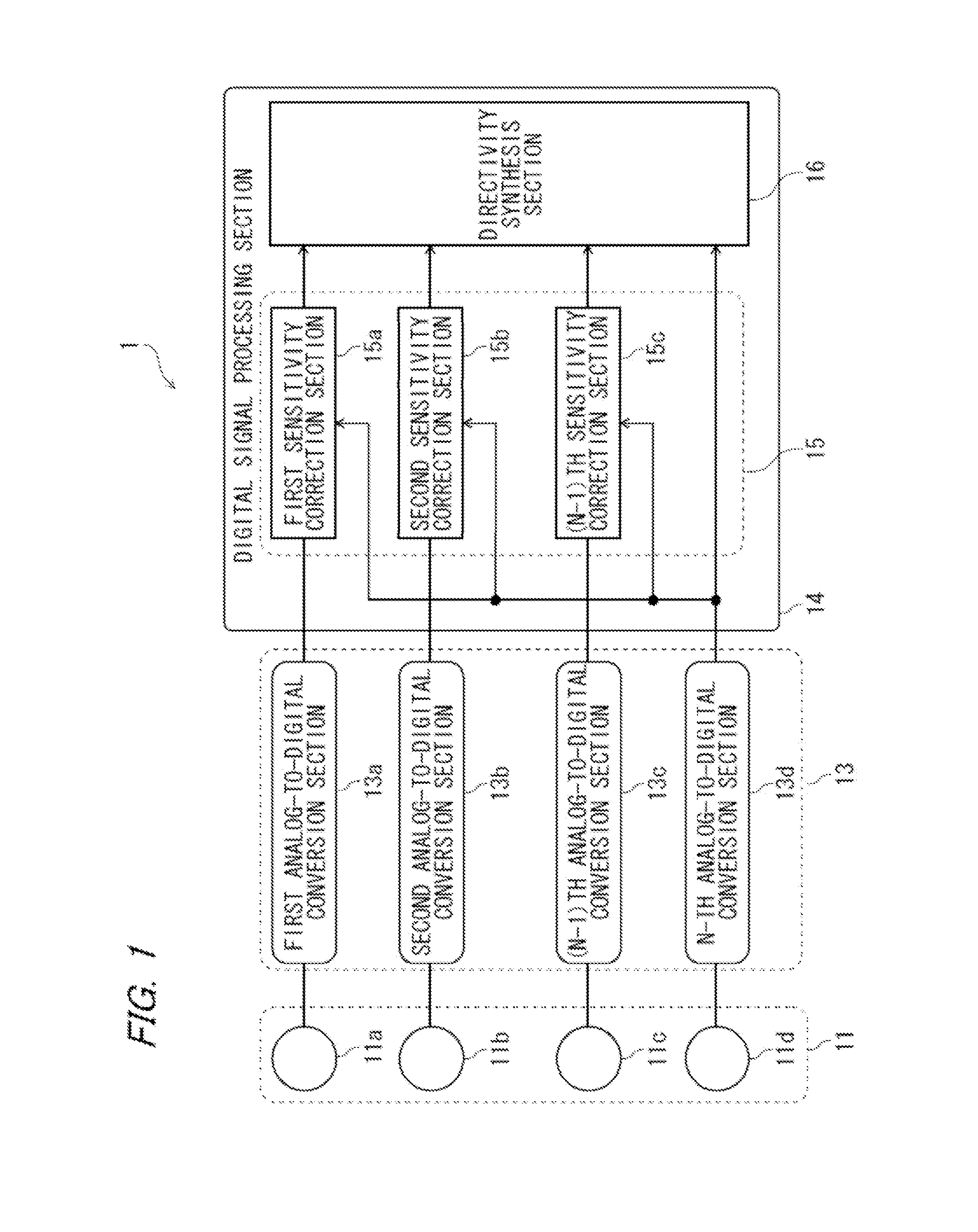
This application is a continuation of PCT application No. PCT/JP2011/004746, which was files on Aug. 25, 2011 based on Japanese Patent Application (No. 2011-134562) filed on Jun. 16, 2013, the contents of which are incorporated herein by reference. Also, all the references cited herein are incorporated as a whole. 1. Technical Field The present invention relates to an array microphone device, and, more specifically, to an array microphone device having a sensitivity correction function. 2. Background Art An array microphone device has been conventionally known as one of directional microphones. The array microphone device, in which a plurality of microphones is arranged, executes the signal processing on the input sound so as to be able to acquire spatial information of a sound that cannot be obtained by a single microphone. Thereby, the directivity control is applied, and estimation can be made for the direction from which the sound is approaching. In recent years, the array microphone device has been used in the directivity control for picking up the sound in a remote sound pickup or an in-car hands-free call system at a high S/N (signal-to-noise) ratio. An array microphone device of this type, which has been known, has such a function (a sensitivity correction function) to correct automatically sensitivity of each of the microphone units, constituting the microphone array, so as to have the identical characteristics (refer to Publication of JP-A-H07-131886, for example). In such an array microphone device, a sensitivity correction means for correcting the sensitivity is provided at the stage prior to a directivity synthesis means for executing the directivity synthesis. Then, the directivity synthesis means operates normally based on the condition such that all of incoming signals are kept at the same level even in the case where the sensitivity of each microphone unit or the sensitivity of associated circuits such as a microphone amplifier (which are simply referred to collectively as the microphone unit sensitivity) are not identical for the reasons of chronological change, manufacturing process, and so on. In the conventional array microphone device, however, when a gain is updated with large amount per hour at the time of amplifying or attenuating a signal from each of the microphone units, this may cause an auditory fluctuation of sound and degradation in distortion rate. Furthermore, since the sensitivity correction function always operates in order to trace chronological change, it is generally required to control the updated amount of gain per hour to be a tiny amount so as to bring no influence on sound quality or distortion rate of sound, those picked up by the array microphone device. Furthermore, in the case where the updated amount of gain once becomes large, this requires a long time to converge the gain in case of the updated amount of gain per hour being made with a tiny amount. Such a circumstances bring about lower performance of the array microphone device at the time of start-up, which might be caused by directivity synthesis failure. Also brought about is to increase in manufacturing cost of the array microphone device for the reason of increased inspection time at the inspection stage in manufacturing. In light of the aforementioned circumstances, the present invention is made, and the purpose thereof is to provide an array microphone device and a gain control method which maintain sound quality and also achieve a high-speed convergence in the sensitivity correction. An array microphone device according to the invention having a microphone array composed of a plurality of microphone units, comprises: a to-be-corrected signal input section configured to input a signal from a microphone unit to be corrected out of the plurality of microphone units as a signal to be corrected; a reference signal input section configured to input a reference signal; a gain variable section configured to amplify or attenuate the signal to be corrected so that a level of the signal to be corrected and a level of the reference signal is substantially equal to each other; and a gain control section configured to control a gain at the time of amplifying or attenuating the signal to be corrected, wherein: the gain control section includes: a first gain update section configured to change the gain with a first amount of change per unit time upon time elapsed since the array microphone device is starting-up being below a predetermined period of time; and a second gain update section configured to change the gain with a second amount of change per unit time upon the elapsed time being above or equal to the predetermined period of time, the second amount of change being smaller than the first amount of change. The structure realizes a quick adjustment in the sensitivity of the microphone unit, which is to be corrected to a reference level at the time of starting-up the array microphone device. Thereby, it is possible to withhold degradation in performance due to directivity synthesis failure, and shorten the inspection time at the inspection stage in manufacturing, which turns out reducing the manufacturing cost. Furthermore, after the start-up operation, the sensitivity of the microphone unit can be also adjusted to the reference sensitivity level but with lower speed at the normal operation time of the array microphone device. Therefore, no influence such as fluctuations in sound is brought to the sound quality, such as picked up by the array microphone device, and the distortion rate is also not degraded. In sum, this invention makes it possible to strike a balance between keeping sound quality and the high-speed convergence in the sensitivity correction. A gain control method in an array microphone device according to this invention having a microphone array composed of a plurality of microphone units, comprises: a to-be-corrected signal input step for inputting by a to-be-corrected signal input section a signal from a microphone unit to be corrected out of the plurality of microphone units as a signal to be corrected; a reference signal input step for inputting a reference signal by a reference signal input section; a gain variable step for amplifying or attenuating the signal to be corrected so that a level of the signal to be corrected and a level of the reference signal is substantially equal to each other; and a gain control step for controlling a gain at the time of amplifying or attenuating the signal to be corrected, wherein: the gain control step includes: a first gain update step for changing the gain with a first amount of change per unit time upon time elapsed since the array microphone device is starting-up being below a predetermined period of time; and a second gain update step for changing the gain with a second amount of change per unit time upon the elapsed time being above or equal to the predetermined period of time, the second amount of change being smaller than the first amount of change. The method realizes a quick adjustment in the sensitivity of the microphone unit, which is to be corrected to a reference level at the time of starting-up the array microphone device. Thereby, it is possible to withhold degradation in performance due to directivity synthesis failure, and shorten the inspection time at the inspection stage in manufacturing, which turns out reducing the manufacturing cost. Furthermore, after the start-up operation, the sensitivity of the microphone unit can be also adjusted to the reference sensitivity level but with lower speed at the normal operation time of the array microphone device. Therefore, no influence such as fluctuations in sound is brought to the sound quality, such as picked up by the array microphone device, and the distortion rate is also not degraded. In sum, this invention makes it possible to strike a balance between keeping sound quality and the high-speed convergence in the sensitivity correction. According to the present invention, it is possible to keep sound quality and also achieve a high-speed convergence in the sensitivity correction. Embodiments of the present invention will be described below in detail with reference to drawings. The microphone array 11 is provided with a first microphone unit 11 The AD conversion section 13 is provided with a first AD conversion section 13 The digital single processing section 14 is connected with each of the AD conversion sections 13 The sensitivity correction section 15 is provided with a first sensitivity correction section 15 The directivity synthesis section 16 synthesizes each of the digital signals (output signals from each of the sensitivity correction sections 15 Then, an operational example of the array microphone device 1 will be described. A sound wave picked up by the microphone array 11 is converted into a digital signal through each of the microphone units 11 Each of the sensitivity correction section 15 Then, the detail of the sensitivity correction section 15 will be described. The signal input section 21 inputs a digital signal from any of each of the A/D conversion sections 13 The reference signal input section 22 inputs a digital signal from the N-th A/D conversion section 13 The gain variable section 23 amplifies or attenuates the level of the signal from any of each of the A/D conversion sections 13 The gain control section 24 controls the amplification amount or the attenuation amount (gain) when the gain variable section 23 amplifies or attenuates the signal to be corrected. The detail of the gain control section 24 will be described below. The signal output section 25 is an output terminal and the like for outputting a signal amplified or attenuated by the gain variable section 23, i.e., an output signal from the gain variable section 23, to the directivity synthesis section 16. Then, the detail of the gain control section 24 will be described. As shown in The band-pass filter 26 is provided with a first band-pass filter 26 The absolute value computing section 27 is provided with a first absolute value computing section 27 The subtraction section 28 subtracts the result computed by the second absolute value computing section 27 The determination section 29 selects either the high-speed gain update section 210 or the low-speed gain update section 211 in order to update the gain. For example, the determination section 29 determines whether or not the time elapsed since the array microphone device 1 is start-up is below a predetermined period of time (such as one second), and selects the high-speed gain update section 210 upon being below the predetermined period of time, while selecting the low-speed gain update section 211 upon being above or equal to the predetermined period of time. The high-speed gain update section 210 updates a gain with a relatively large updated amount of gain per unit time (a first amount of change). The low-speed gain update section 211 updates a gain with a relatively small updated amount of gain per unit time (a second amount of change smaller than the first amount of change). Since the sensitivity correction section 15 is structured as described above, the signal to be corrected, which comes from any of microphone units 11 Furthermore, with regard to the output signal from the gain variable section 23, the magnitude of the signal to be corrected whose band is limited by the first band-pass filter 26 On the other hand, with regard to the reference signal from the microphone unit 11 Then, the description will be made regarding an example of a gain update by the high-speed gain update section 210 and the low-speed gain update section 211. Here, it is assumed that ±4 dB at the maximum is the difference in sensitivity (difference in gain) between any of the microphone units 11 When the array microphone device 1 is turned on and start-up, an elapse time counter (not shown) in the digital signal processing section 14 carries out the update operation for each sampling period, i.e, starts timing (step S101). Then, the determination section 29 determines whether or not the elapse time counter has counted less than one second (step S102). If the elapse time counter has counted one second or more, the determination section 29 selects the high-speed gain update section 210 (No at step S102). Subsequently, the high-speed gain update section 210 determines whether or not the result of the subtraction by the subtraction section 28 is positive (step S103). If the subtracted result by the subtraction section 28 is positive, it means that the level of the signal to be corrected from the gain variable section 23 is higher than the level of the reference signal, and thus the high-speed gain update section 210 carries out the update for decreasing the gain (step S104). At this time, the high-speed gain update section 210 is set the updated amount of gain per one sampling period to be, for example, −0.00025 dB (corresponding to −4 dB at 16000 samples that is the number of samples for one second). Furthermore, if the result of the subtraction by the subtraction section 28 is negative, it means that the level of the signal to be corrected from the gain variable section 23 is lower than the level of the reference signal, and thus the high-speed gain update section 210 carries out the update for increasing the gain (step S105). At this time, the high-speed gain update section 210 sets the updated amount of gain per one sampling period to be, for example, +0.00025 dB (corresponding to +4 dB at 16000 samples that is the number of samples for one second). Then, the high-speed gain update section 210 updates the gain with the updated amount of gain concerned, and then sets the gain in the gain variable section 23 (step S106). In this manner, the high-speed gain update section 210 speedily corrects the difference in sensitivity corresponding to the result of the subtraction by the subtraction section 28 with a predetermined period of time after the start-up (such as one second). It is thus possible to shorten the duration to the degradation of directivity during the sensitivity correction (during the gain update), and also cut the waiting time at the inspection stage down to the predetermined period of time mentioned above (such as one second). On the other hand, if the elapse time counter has counted one second or more, the determination section 29 selects the low-speed gain update section 211 (Yes at step S102). Subsequently, the high-speed gain update section 210 determines whether or not the result of the subtraction by the subtraction section 28 is positive (step S107). If the result of the subtraction by the subtraction section 28 is positive, it means that the level of the signal to be corrected from the gain variable section 23 is higher than the level of the reference signal, and thus the low-speed gain update section 211 carries out the update for decreasing the gain (step S108). At this time, the updated amount of gain per one sampling period is set to be, for example, −0.0000025 dB (corresponding to −0.04 dB at 16000 samples that is the number of samples for one second). Furthermore, if the result of the subtraction by the subtraction section 28 is negative, it means that the level of the signal to be corrected from the gain variable section 23 is lower than the level of the reference signal, and thus the low-speed gain update section 211 carries out the update for increasing the gain (step S109). At this time, the updated amount of gain per one sampling period is set to be, for example, +0.0000025 dB (corresponding to +0.04 dB at 16000 samples that is the number of samples for one second). Then, the low-speed gain update section 211 updates the gain with the updated amount of gain concerned, and then sets the gain in the gain variable section 23 (step S106). In this manner, the low-speed gain update section 211 confines the updated amount of gain on the order of ±0.04 dB per one second. Thus, even though the update of the gain is always conducted, the sound quality does not become degraded and the update operation can be prevented from being auditorily recognized. Then, the description will be made regarding an example of the update of the gain updated by the high-speed gain update section 210 and the low-speed gain update section 211. Then, the description will be made regarding a frequency characteristic of the directivity depending on the presence of the sensitivity correction (gain update). Referring to In accordance with the array microphone device 1 of this type of the present embodiment, the gain in the gain variable section 23 is increased and decreased at high speed at the time of start-up the array microphone array device 1, while increased and decreased with lower speed at the normal operation time, so that the level of each of the output signals from the sensitivity correction sections 15 When the array microphone device 1 is turned on and start-up, the determination section 29 computes a level sum of the level of the output signal 31 If it is determined that the level sum is above the threshold value, the elapse time counter carries out the update operation in the digital signal processing section 14, i.e., starts timing (step S203). The subsequent operations are similar to steps S102 to S109 in In this manner, the array microphone device 1 of the present embodiment changes the gain by the high-speed gain update section 210 (an example of the first gain update section) when the time elapsed since the sum of the level of the signal to be corrected and the level of the reference signal is below the predetermined value, while changing the gain by the low-speed gain update section 211 (an example of the second gain update section) when the elapsed time described above is above or equal to the predetermined period of time. Therefore, only when the sound is sufficiently picked up by the microphone units 11 In addition, the sampling frequency, the gain, the operating time of the high-speed gain update section 210, the threshold value and the like are not limited to those described above. Furthermore, the high-speed gain update section 210 may determine the updated amount of gain from the gain and the acceptable correction time. Furthermore, the low-speed gain update section 211 may set the updated amount of gain to be the amount of change in level that does not give a feeling of being unreasonable auditorily. In this case, 0.1 dB or less per one second is desirable, for example. While the present invention has been described in detail, or with reference to the specific embodiments, it is apparent for those skilled in the art that the invention may be modified and changed in various manners without departing from the scope and spirit of the invention. The present invention is useful for an array microphone device and the like which keeps sound quality as well as achieves a high-speed convergence in sensitivity correction. The array microphone device has a microphone array composed of a plurality of microphone units, having a signal input section for inputting a signal from the microphone units to be corrected as a signal to be corrected; a reference signal input section; a gain variable section for making the levels of the signal to be corrected and the reference signal equal; and a gain control section. The gain control section includes a high-speed gain update section for changing the gain with a first amount of change per unit time upon time elapsed since the array microphone device is starting-up being below a predetermined period of time; and a low-speed gain update section for changing the gain with a second amount of change per unit time upon the elapsed time being above the predetermined period of time, the second amount of change being smaller than the first amount of change. 1. An array microphone device having a microphone array composed of a plurality of microphone units, comprising:
a to-be-corrected signal input section configured to input a signal from a microphone unit to be corrected out of the plurality of microphone units as a signal to be corrected; a reference signal input section configured to input a reference signal; a gain variable section configured to amplify or attenuate the signal to be corrected so that a level of the signal to be corrected and a level of the reference signal is substantially equal to each other; and a gain control section configured to control a gain at the time of amplifying or attenuating the signal to be corrected, wherein: the gain control section includes: a first gain update section configured to change the gain with a first amount of change per unit time upon time elapsed since the array microphone device is starting-up being below a predetermined period of time; and a second gain update section configured to change the gain with a second amount of change per unit time upon the elapsed time being above or equal to the predetermined period of time, the second amount of change being smaller than the first amount of change. 2. The array microphone device according to the gain control section changes the gain by the first gain update section upon time elapsed since a sum of the level of the signal to be corrected and the level of the reference signal is above the predetermined value being below the predetermined period of time, while changing the gain by the second gain update section upon the elapsed time being above or equal to the predetermined period of time. 3. The array microphone device according to the reference signal input section inputs the signal from a microphone unit other than the microphone unit to be corrected out of the plurality of microphone units, as the reference signal. 4. The array microphone device according to the first amount of change is the amount of change based on a difference between the level of the signal to be corrected and the level of the reference signal, and the predetermined period of time. 5. The array microphone device according to the second amount of change is the amount of change that is auditorily unperceivable. 6. The array microphone device according to the first amount of change is 1 dB or more per one second; and the second amount of change is below 1 dB per one second. 7. A gain control method in an array microphone device having a microphone array composed of a plurality of microphone units, comprising:
a to-be-corrected signal input step for inputting by a to-be-corrected signal input section a signal from a microphone unit to be corrected out of the plurality of microphone units as a signal to be corrected; a reference signal input step for inputting a reference signal by a reference signal input section; a gain variable step for amplifying or attenuating the signal to be corrected so that a level of the signal to be corrected and a level of the reference signal is substantially equal to each other; and a gain control step for controlling a gain at the time of amplifying or attenuating the signal to be corrected, wherein: the gain control step includes: a first gain update step for changing the gain with a first amount of change per unit time upon time elapsed since the array microphone device is starting-up being below a predetermined period of time; and a second gain update step for changing the gain with a second amount of change per unit time upon the elapsed time being above or equal to the predetermined period of time, the second amount of change being smaller than the first amount of change. CROSS REFERENCE TO RELATED APPLICATION
BACKGROUND OF THE INVENTION
SUMMARY
BRIEF DESCRIPTION OF THE DRAWINGS
DETAILED DESCRIPTION OF THE EXEMPLARY EMBODIMENTS
First Embodiment
Second embodiment