BIDET WASHING APPARATUS
This application claims the benefit, under 35 U.S.C. §119(e), of U.S. Provisional Application 61/712,464, filed Oct. 11, 2012, entitled “Bidet Washing Apparatus,” the contents of which are incorporated by reference herein in their entirety. Embodiments of the present disclosure relate to a bidet washing apparatus, for use with a toilet bowl, which can provide for the cleaning of body parts of a person sitting on or near the bowl. One conventional method of cleaning oneself after toilet use is with paper, which is not always available and is sometimes so rough as to aggravate the skin. Moreover, such paper not infrequently causes plumbing problems by clogging up the toilet at the time of flushing. Bidet apparatus for washing and cleaning the body parts (e.g., genital and/or anal) using water were initially developed in the form of a bidet that provided a single spray of water and was conventionally permanently built into the bowl. However, such bidets were expensive and a new generation of bidets attachable to the toilet was then developed with a plurality of nozzles for multiple water sprays. Such bidets can be attached to the seat of an existing toilet bowl for washing the private parts of a person sitting on it, using washing water sprayed from the bidet nozzles, without the use of toilet paper. Such bidets may include a plurality of nozzles for washing the private parts as well as the bidet itself. Various designs have addressed some of the desired effects, such as washing, washing with temperature-regulated water, and drying. However, existing bidets fail to address all concerns related to the designs and functions in the general field of bidets. For example, pollution of the outer surface of the nozzles, the bidet and toilet during utilization is a common problem and causes aesthetic and hygienic issues. This is particularly important in bidets used, for example, by infirm or sick people who have to be especially cautious about maintaining hygiene and preventing infections. Some mobile cleaning and bidet systems may exist which operate according to various techniques in order to overcome these problems. Some such bidets comprising mobile cleaning have an electrical or mechanical system to retract the nozzles within a cylindrical covering to prevent pollution. The nozzle moves forward within the body of the cylinder and becomes active either by electrical or by a mechanical signal. The nozzle is retracted upon usage of the toilet. The mechanical signal acts by the force of the washing water that pushes the nozzle out of its outer covering and thus washing water is sprayed on the person sitting on the toilet. When the washing water supply is stopped, the nozzle is retracted. Therefore, when a user uses the lavatory, the user's excrement is not splattered directly on the nozzle pipes since the nozzle pipes are accommodated within the outer covering. Thus the pollution of the nozzles is prevented to some extent. However, this is not very efficient and does not adequately solve the hygiene related issues. For example, the nozzle pipes may still become dirty when the user is being washed by the washing water sprayed from the nozzle. Some bidets overcome this by allowing the user to pull out the nozzle manually and clean the nozzle after use. However, this is both cumbersome and unpleasant. Some other bidets have a cleaning nozzle to wash the washing nozzles after usage. However, this is also undesirable because of nozzle positions and dripping of the nozzle cleaning water. Another problem with the existing bidet systems is the existence of multiple joints between the water inlets and the control valves of the bidet. Such joints are unwieldy and also considerably reduce the life of the bidet because of the possibility of breaking or leakage of one of the numerous joints. It is, thus, desirable to engineer a single connection between a water inlet and a control valve, which conventional bidets have failed to accomplish. The presently disclosed embodiments are directed to solving one or more of the problems presented in the prior art, described above, as well as providing additional features that will become readily apparent by reference to the following detailed description when taken in conjunction with the accompanying drawings. Accordingly, one object of the present disclosure is to provide a bidet washing apparatus attachable to a toilet bowl for cleaning one or more body parts of a user. The apparatus can include one or more water inlets configured to supply water, and a control unit, housing one or more valves fluidically connected to the one or more water inlets, including one or more control switches configured to operate the one or more valves. As such, the one or more valves can control water flow from the one or more water inlets. The apparatus can further include a nozzle assembly including at least one washing nozzle, fluidically connected to at least one of the one or more valves with one or more water tubes. The at least one washing nozzle can be positioned for directing water to the one or more body parts of the user. The apparatus can also include a protective shield gate covering at least a portion of the at least one washing nozzle, where the protective shield gate is rotatably coupled to the bidet washing apparatus. According to various embodiments, the protective shield gate can be rotatably coupled to the apparatus along a side or top edge via a hinge, for example, in order to allow for the manual or electrical opening and closing of the protective shield gate. In this manner, the nozzle(s) are easily accessible for cleaning, removal, replacement or other adjustment while the protective shield gate is open. In an alternative embodiment, the protective shield gate can be completely removed to similarly provide access to the nozzle(s). According an embodiment, the water inlet(s) can be fluidically connected to one or more valves via a single-body connector without any intervening parts or joints, which results in a more robust, long-lasting, bidet washing apparatus, since leaks or other damage to the fluidic couplings are less likely to occur. Further features and advantages of the present disclosure, as well as the structure and operation of various embodiments of the present disclosure, are described in detail below with reference to the accompanying drawings. The present disclosure, in accordance with one or more various embodiments, is described in detail with reference to the following figures. The drawings are provided for purposes of illustration only and merely depict exemplary embodiments of the disclosure. These drawings are provided to facilitate the reader's understanding of the disclosure and should not be considered limiting of the breadth, scope, or applicability of the disclosure. It should be noted that for clarity and ease of illustration these drawings are not necessarily made to scale. The following description is presented to enable a person of ordinary skill in the art to make and use embodiments described herein. Descriptions of specific devices, techniques, and applications are provided only as examples. Various modifications to the examples described herein will be readily apparent to those of ordinary skill in the art, and the general principles defined herein may be applied to other examples and applications without departing from the spirit and scope of the disclosure. Thus, the present disclosure is not intended to be limited to the examples described herein and shown, but is to be accorded the scope consistent with the claims. The word “exemplary” is used herein to mean “serving as an example illustration.” Any aspect or design described herein as “exemplary” is not necessarily to be construed as preferred or advantageous over other aspects or designs. Reference will now be made in detail to aspects of the subject technology, examples of which are illustrated in the accompanying drawings, wherein like reference numerals refer to like elements throughout. It should be understood that the specific order or hierarchy of steps in the process disclosed herein is an example of exemplary approaches. Based upon design preferences, it is understood that the specific order or hierarchy of steps in the processes may be rearranged while remaining within the scope of the present disclosure. Any accompanying method claims present elements of the various steps in a sample order, and are not meant to be limited to the specific order or hierarchy presented. Embodiments disclosed herein describe a new, clean and hygienic washing bidet. Various embodiments comprise one or a plurality of water inlets, a control means housing one or a plurality of control valves to control the flow of water from the water inlet(s) to one or a plurality of water tubes, one or a plurality of washing nozzles, a protective shield gate, and securing unit configured to securing the sanitary washing device to the toilet seat. Embodiments of the present disclosure are directed to a clean and hygienic bidet washing apparatus 100 attachable to an existing toilet for cleaning the body parts of the user sitting on or near the toilet. As described herein, a “bidet” is a toilet attachment for cleaning the body parts of the user. The term “water inlet” means any structure that may provide water to the bidet washing apparatus. “Control unit” (aka “control panel”) is the housing which has “control switche(s)” thereon controlling the various functionalities of the bidet, including but not limited to, flow of water, adjusting the angle of the nozzles, and opening and closing the protective shield gate. “Control valves” are controller parts located inside the control panel housing which control the flow of water or other fluids from the water inlet(s) to one or more “water tubes” by opening, closing or partially obstructing various passageways. “Water tubes” are channels that connect the control valves to a “nozzle assembly,” wherein, the “nozzle assembly” includes a single nozzle or a collection of nozzles comprising at least one “washing nozzle.” “Nozzle” is a device designed to eject water or other fluids into the surrounding medium as a coherent controlled spray. The “washing nozzle” is the nozzle that can be used to wash the body parts of a user. The nozzle assembly may also have other types of nozzles such as a “self cleaning nozzle,” which is used to clean the nozzle assembly itself, a “toilet cleaning nozzle,” which is used to clean the bidet and/or the toilet, and a “shield cleaning nozzle,” which is used for cleaning the “protective shield gate.” The “protective shield gate” is a structure placed at least partially in front of the nozzle assembly (e.g., between the user and the nozzle assembly) to protect the nozzle assembly from pollutants. The “protective shield gate” can have a “hinged” edge. The term “hinged” here means a joint that allows the turning or pivoting of the gate, by any conventional turning or pivoting mechanism. The term “fluidically coupled” means a connection or a passageway which allows fluid to flow therethrough. The term “reservoir” means a fluid holding tank. Referring to A control unit 108 can be provided for easy access for the user, and houses control switches 102 Furthermore, as shown in Certain aspects of the bidet washing apparatus will be detailed hereinafter with reference to Referring to In certain embodiments, the protective shield gate 104 has a flap portion perpendicular to the shield gate 104 such that it covers the bottom of the nozzle assembly 101. Additionally, the flap can have a spring mechanism such that it is pushed out and aligns with the shield gate 104 by the force of the water stream when water flows out of the nozzle assembly 101. When the water flow stops, the flap can spring back into its original position perpendicular to the shield gate 101. The protective shield gate 104 of the present disclosure can be made from a material selected from the group comprising plastic, metal, material having anti-microbial properties, and material with increased pollutant repellant properties. In certain embodiments, the angle of the washing nozzles may be adjusted using control switche(s) located on the control unit 108. Thus, when a user wants to clean certain body parts, water may be sprayed on a desired body part by adjusting the angle of the washing nozzle(s). In the present embodiment as shown in According to the present embodiment, the nozzle assembly 101 comprises at least one washing nozzle. In yet another embodiment, the bidet washing apparatus 100 further comprises a self cleaning nozzle for cleaning the nozzle assembly itself. The self cleaning nozzle can be positioned to spray water onto the nozzle assembly 100 and/or washing nozzle(s) before and/or after usage for additional hygiene. The self cleaning nozzle may be adapted to be controlled by the control unit 108, and thus provides an additional hygiene level. Another embodiment comprises a toilet cleaning nozzle for cleaning the toilet and the bidet before and after use of the toilet. The toilet cleaning nozzle can be positioned to spray water on the toilet bowl 110 and/or the bidet apparatus 100, and may be controlled by the control unit to provide additional hygiene. Yet, another embodiment comprises a shield cleaning nozzle for cleaning the protective shield gate 104. The shield cleaning nozzle may be similarly controlled by the control unit 108. Additionally, the shield cleaning nozzle may be positioned to clean the shield gate 104 in an open and/or closed position. Any or all of the washing nozzles may be connected to the nozzle assembly 101 via a ball joint, for example, which could allow the user to manually swivel a washing nozzle around 360 degrees, in order to direct the spray of water in a desired and precise direction. Of course, other types of joints and connectors could be implemented in order to allow for the manual swivel or direction correction, as desired by the user to spray water to a desired body part, for example. Moreover, according to an exemplary embodiment, one or more of the washing nozzle(s) 101 According to an embodiment, a washing nozzle can be replaced with a nozzle that is configured to hold materials such as soap, disinfectant or any medicinal substance which can be expelled along with water as it flows through the nozzle. For example, such materials could be in a solid form, which dissolves at a predetermined and desired rate, as the water flows through the nozzle and is carried out of the nozzle by the spraying water. The above-mentioned materials are provided merely for exemplary purposes and are not intended to limit the disclosure in any way. Other substances/materials could be held/stored in a nozzle in order to be expelled with water through the nozzle. An exemplary water supply system to the nozzle assembly 101 will be detailed hereinafter with reference to The control valves 106 According to an embodiment, the bidet washing apparatus 100 can include a vacuum breaker (not depicted), which can be situated at various locations within the bidet washing apparatus 100. The vacuum breaker can be located anywhere between the water supply (e.g., the water tank supplying water to the toilet bowl) and the washing nozzle(s) (e.g., 101 In one exemplary embodiment, each water inlet 103 As a result of the foregoing description, a bidet washing apparatus is provided with an objective of satisfactorily and hygienically washing a user's body parts after toilet use. The protective shield gate, according to embodiments described herein, can provide advanced hygiene by protecting the nozzle(s) from excrement, while allowing for the easy cleaning and/or replacement of nozzle(s) as desired. Moreover, the single-body design of the connector between the water inlet(s) and the valve(s) provides for enhanced durability of the bidet washing apparatus, with decreased risk of leakage. While the inventive features have been particularly shown and described with reference to preferred embodiments thereof, it will be understood by those in the art that the foregoing and other changes may be made therein without departing from the sprit and the scope of the disclosure. Likewise, the various diagrams may depict an example architectural or other configuration for the disclosure, which is done to aid in understanding the features and functionality that can be included in the disclosure. The disclosure is not restricted to the illustrated example architectures or configurations, but can be implemented using a variety of alternative architectures and configurations. Additionally, although the disclosure is described above in terms of various exemplary embodiments and implementations, it should be understood that the various features and functionality described in one or more of the individual embodiments are not limited in their applicability to the particular embodiment with which they are described. They instead can be applied alone or in some combination, to one or more of the other embodiments of the disclosure, whether or not such embodiments are described, and whether or not such features are presented as being a part of a described embodiment. Thus, the breadth and scope of the present disclosure should not be limited by any of the above-described exemplary embodiments. A bidet washing apparatus attachable to a toilet bowl for cleaning one or more body parts of a user is disclosed. The apparatus can include one or more water inlets configured to supply water, and a control unit, housing one or more valves connected to the one or more water inlets, including one or more control switches configured to operate the one or more valves. The apparatus can include a nozzle assembly with at least one washing nozzle fluidically connected to at least one of the valves with one or more water tubes. The at least one washing nozzle can be positioned for directing water to the body parts of the user. The apparatus can also include a protective shield gate covering at least a portion of the at least one washing nozzle, where the protective shield gate is rotatably coupled to the bidet washing apparatus. 1. A bidet washing apparatus attachable to a toilet bowl for cleaning one or more body parts of a user, comprising:
one or more water inlets configured to supply water; a control unit, housing one or more valves fluidically connected to the one or more water inlets, including one or more control switches configured to operate the one or more valves, wherein the one or more valves control water flow from the one or more water inlets; a nozzle assembly including at least one washing nozzle, fluidically connected to at least one of said one or more valves with one or more water tubes, wherein said at least one washing nozzle is positioned for directing water to the one or more body parts of the user; a protective shield gate covering at least a portion of the at least one washing nozzle, wherein the protective shield gate is rotatably coupled to the bidet washing apparatus. 2. A bidet washing apparatus according to 3. A bidet washing apparatus according to 4. A bidet washing apparatus according to 5. A bidet washing apparatus according to 6. A bidet washing apparatus according to 7. A bidet washing apparatus according to 8. A bidet washing apparatus according to 9. A bidet washing apparatus according to 10. A bidet washing apparatus according to 11. A bidet washing apparatus according to 12. A bidet washing apparatus according to 13. A bidet washing apparatus according to 14. A bidet washing apparatus according to 15. A bidet washing apparatus according to 16. A bidet washing apparatus according to 17. A bidet washing apparatus according to 18. A bidet washing apparatus according to 19. A bidet washing apparatus according to 20. A bidet washing apparatus according to 21. A bidet washing apparatus according to CROSS-REFERENCE TO RELATED APPLICATIONS
FIELD
BACKGROUND
SUMMARY
BRIEF DESCRIPTION OF THE DRAWINGS
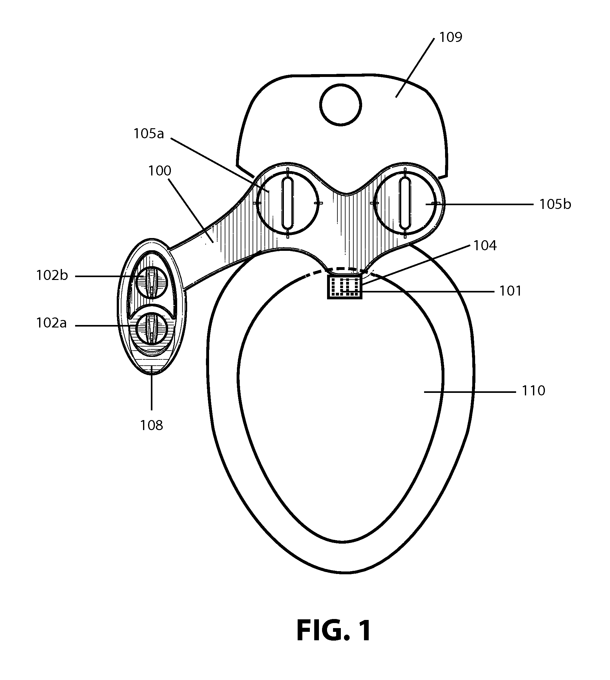
DETAILED DESCRIPTION OF EXEMPLARY EMBODIMENTS