ROLLING BEARING, NOTABLY FOR SHIP'S PROPELLER OR FOR WIND TURBINE
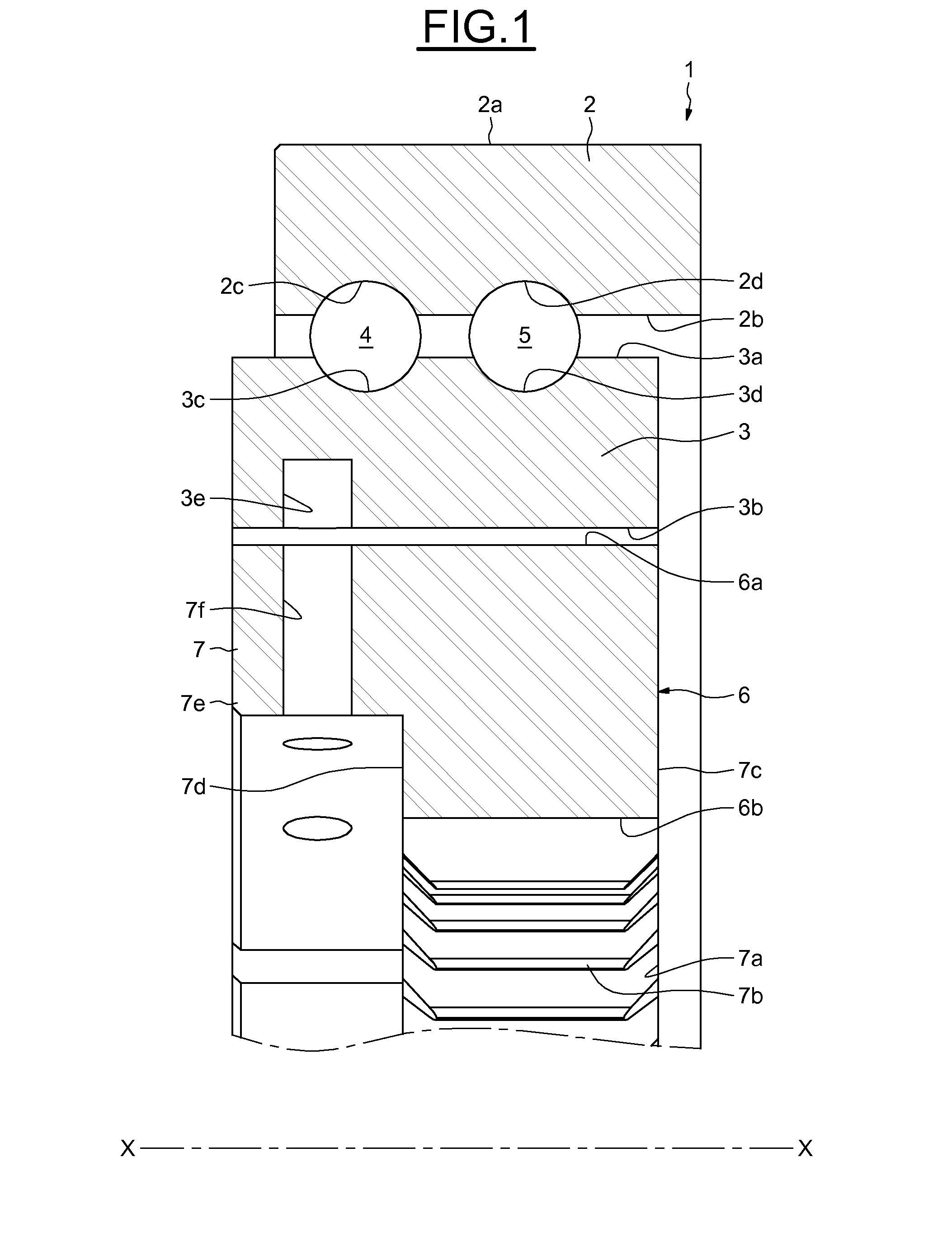
This application claims priority to French Patent Application No. FR1260016 filed on Oct. 22, 2012, the contents of which is fully incorporated herein by reference. The present invention relates to the field of rolling bearings and notably relates to rolling bearings used in the field of ship's propellers or wind turbines. A “ship” means a high-tonnage vessel intended for maritime shipping, such as merchant shipping (oil tankers, container ships, fishing boats, etc.), warships (aircraft carriers, submarines, etc.) or alternatively large sailing boats or cruise liners. A ship's propeller typically takes the form of an assembly comprising an engine which drives the rotation of at least one propeller screw, this propeller being fixed to the hull of the ship, notably at the rear of the ship. In order to steer the ship, it is known practice to use what is known as a “pitch bearing” in order to orientate the propeller with respect to the hull of the ship. A wind turbine generally comprises a nacelle, mounted for rotation on a mast and enclosing a generator intended to produce electrical energy, a rotor driven by the wind and provided with a hub supporting at least two blades, and a large-sized rolling bearing supporting the rotor. In order to control the load supplied to the rotor, it is common to use a pitch bearing in order to orientate the blades of the wind turbine about their longitudinal axis according to the wind direction. Such a rolling bearing comprises an outer ring fixed to the hub, an inner ring fixed to one of the blades and a plurality of rolling elements, such as balls, arranged between the inner and outer rings. The rolling bearing comprises a ring gear provided with a peripheral inner gear teeth intended to mesh with an actuator via a gearwheel. It is known practice to form the internal gear teeth directly on the inner surface of the inner ring. However, such a rolling bearing referred to as a pitch bearing works only when it is necessary to orientate the blade or the propeller and performs small rotations, such that only a small portion of the gear teeth is used. In addition, such a rolling bearing may be stationary for long periods of time, thus causing accelerated degradation. As the gear teeth wears, it becomes necessary to dismantle the inner ring, or even the rolling bearing in its entirety, which is a relatively complex and expensive operation. Reference may be made to document EP 2 474 735 which describes a device for mounting a blade pitch gear on a pitch bearing of a wind turbine comprising an inner ring, an outer ring and a gear which is fixed to the inner ring by a plurality of fixing means. Although such a device allows only the gear to be changed in the event of wear, the plurality of fixing means generates great overall external dimensions and is complicated to achieve. Reference may also be made to document U.S. Pat. No. 7,331,761 which describes a blade pitch bearing for a wind turbine comprising an inner ring, an outer ring and two rows of rolling elements which are arranged between the rings. The inner surface of the inner ring is provided with a plurality of teeth over a portion less than 200° and intended to mesh with a gear in order to orientate the blades of the wind turbine. However, as the gear teeth wears, it then becomes necessary to remove the inner ring in its entirety. It is therefore an object of the present invention to remedy these disadvantages. More specifically, the present invention seeks to provide a rolling bearing that is easy to manufacture, to fit, is of small overall external dimensions, and allows the meshing means to be removed quickly and economically. The invention concerns a rolling bearing comprising an inner ring, an outer ring, at least one row of rolling elements which are arranged between raceways made on the said rings and a ring gear fixed to one of the said rings. The ring gear is formed of at least two independent gear segments which are each provided on their inner or outer peripheral surface with a plurality of meshing means and fixed only to one of either the inner or outer rings of the rolling bearing, the circumference of the ring gear being substantially equal to the circumference of the combination of the independent gear segments. Thus, the damaged gear segment can be removed without removing the other, undamaged, gear segments. Nor is there any longer any need to remove in its entirety the inner or outer ring to which the independent gear segments are fixed, or even the rolling bearing in its entirety, allowing a simplified disassembling. Advantageously, each gear segment comprises an axial portion extending axially from a radial surface of the gear segment. Each of the axial portions may comprise at least one radial drilling intended to cooperate with an attachment means to one of the inner or outer rings. According to one embodiment, each gear segment comprises a radial portion extending radially from the axial portion in the opposite direction to the radial teeth. Each of the radial portions may comprise at least one axial drilling intended to cooperate with an attachment means to one of the inner or outer rings. According to one embodiment, the ring gear is fixed to the peripheral inner surface of the inner ring, the said independent gear segments each being provided on their inner peripheral surface with a plurality of meshing means. According to one embodiment, the circumference of the ring gear is less than or equal to 360°, preferably less than or equal to 120°. Indeed, when the blade is orientated, the rolling bearing makes small rotations such that only a small portion of the gear teeth is used. Use of a ring gear with a circumference of 120°or less is then sufficient and allows a significant reduction in materials. For example, the ring gear is formed of four independent gear segments each extending circumferentially over substantially 90°, or of six independent gear segments each extending circumferentially over substantially 60°. Advantageously, the meshing means are radial teeth, for example designed to cooperate with a gearwheel, such as a pinion gear. According to a second aspect, the invention concerns a wind turbine comprising a nacelle, mounted on a mast and enclosing a generator intended to produce electrical energy, a rotor provided with a hub supporting at least two blades and a rolling bearing as described hereinabove mounted between the hub and a blade. According to another aspect, the invention relates to a ship comprising a hull, a propeller enclosing an engine and propeller screws, and a rolling bearing as described hereinabove mounted between the hull and the propeller. The present invention will be better understood from reading the description of a number of embodiments which are given by way of nonlimiting examples and illustrated by the attached drawings in which: The rolling bearing, of axial axis X-X, referenced 1 in By way of non-limiting example, a wind turbine comprises a nacelle placed at one end of a mast and a rotor provided with a hub supporting at least two blades which are powered by the wind in order to produce electrical energy. The rolling bearing 1 is designed to be placed between the hub of the rotor and one of the blades and used to orientate the blades of the wind turbine about their longitudinal axis according to the wind direction. The rolling bearing 1 comprises an outer ring 2 designed to be fixed to the hub (not depicted) by its cylindrical outer surface 2 The outer 2 and inner 3 rings are solid. What is meant by “solid ring” is a ring the shape of which is obtained by machining with the removal of chips (turning, grinding) from tubes, bar stock, forged and/or rolled blanks. The outer ring 2 comprises, at its bore 2 In another preferred embodiment of the invention (which has not been depicted), each raceway 2 The rolling bearing 1 comprises a ring gear 6 of annular shape extending circumferentially over 360° and designed to be fixed to one of the inner or outer rings. As an alternative, it is possible to conceive a ring gear that has a circumference of less than 360°, or even of 120° or less. In the example illustrated, the outer surface 6 The ring gear 6 illustrated in detail in It will be noted that a number of segments higher than or equal to two could be provided. The gear segments may have circumferential lengths that differ from one another, while at the same time having a total circumference substantially equal to the circumference of the ring gear. The total circumference of the ring gear corresponds to the sum of the circumferences of each of the independent gear segments. By way of non-limiting example, provision could be made for the ring gear to be formed of two independent gear segments, each having a circumference of substantially 45°, so that the ring gear has a circumference of 90°. In the example illustrated in As illustrated in Each gear segment 7, 8, 9, 10, 11, 12 comprises two lateral radial surfaces 7 Only segment 7 will be described hereinafter, it being understood that segments 8, 9, 10, 11 and 12 are identical to segment 7. The gear segment 7 comprises an axial portion 7 Alternatively, these attachment means may be limited to a positioning means, such as centring pegs or a supporting shoulder. The embodiment illustrated in As illustrated in Each of the gear segments 15, 16, 17, 18 is provided on its inner peripheral surface 15 Each gear segment 15, 16, 17, 18 comprises two lateral radial surfaces 15 The embodiment illustrated in As illustrated in It will be noted that a number of gear segments greater than or equal to two may be provided. As an alternative, the gear segments may have different circumferential lengths, while at the same time forming a ring gear of substantially 360°. As illustrated in Each gear segment 21, 22, 23, 24 comprises two lateral radial surfaces 21 Each gear segment 21, 22, 23, 24 comprises an axial portion 21 By virtue of the invention, as the gear teeth wears, it is easy to remove the damaged gear segment without removing the other, undamaged, gear segments and without fully removing the inner ring or even the rolling bearing in its entirety. The special structure of the gear segments allows for ease of attachment to the inner ring, either radially or axially. It will be noted that the rolling bearing 1 according to the invention could also be used in a high-tonnage ship (not depicted). A ship generally comprises a propeller comprising an engine and at least one propeller screw for propelling the ship. The propeller is mounted on the hull of the ship, notably at the rear of the ship, via the rolling bearing 1. As high-tonnage ships generally have no steering rudder, the rolling bearing 1 allows the propeller to be orientated with respect to the hull of the ship in order to steer the ship. Rolling bearing (1) comprising an inner ring (3), an outer ring (2), at least one row of rolling elements which are arranged between raceways made on the rings (2, 3) and an ring gear (6) fixed to one of the rings (2). The ring gear (6) is formed of at least two independent gear segments (7, 8, 9, 10, 11, 12) which are each provided on their inner or outer peripheral surface with a plurality of meshing means (7b, 8b, 9b, 10b, 11b, 12b) and fixed only to one of either the inner or outer rings (3) of the rolling bearing (1), the circumference of the ring gear (6, 20) being substantially equal to the circumference of the combination of the independent gear segments. 1. A rolling bearing (1) comprising:
an inner ring (3), an outer ring (2), at least one row of rolling elements (4) disposed between raceways (2 a ring gear (6, 20) fixed to one of the inner and outer rings (3, 2), wherein the ring gear (6, 20) is formed of at least two independent gear segments (7 to 12; 15 to 18; 21 to 24) each provided on one of an inner and outer peripheral surface with a plurality of meshing means and fixed to one of the inner and outer rings (3, 2) of the rolling bearing (1), and wherein the circumference of the ring gear (6, 20) is substantially equal to the circumference of the combination of the independent gear segments. 2. The rolling bearing according to 3. The rolling bearing according to 4. The rolling bearing according to 5. The rolling bearing according to 6. The rolling bearing according to 7. The rolling bearing according to 8. The rolling bearing according to 9. The rolling bearing according to 10. The rolling bearing according to 11. A wind turbine comprising:
a nacelle, mounted on a mast and enclosing a generator intended to produce electrical energy, a rotor provided with a hub supporting at least two blades, and a rolling bearing (1) mounted between the hub and a blade, the rolling bearing including,
an inner ring (3), an outer ring (2), at least one row of rolling elements (4) disposed between raceways (2 a ring gear (6, 20) fixed to one of the inner and outer rings (3, 2), wherein the ring gear (6, 20) is formed of at least two independent gear segments (7 to 12; 15 to 18; 21 to 24) each provided on one of an inner and outer peripheral surface with a plurality of meshing means and fixed to one of the inner and outer rings (3, 2) of the rolling bearing (1), and wherein the circumference of the ring gear (6, 20) is substantially equal to the circumference of the combination of the independent gear segments. 12. The rolling bearing according to CROSS-REFERENCE TO RELATED APPLICATION
FIELD OF THE INVENTION
BACKGROUND OF THE INVENTION
SUMMARY OF THE INVENTION
BRIEF DESCRIPTION OF THE FIGURES
DETAILED DESCRIPTION OF THE INVENTION