VORTEX CHAMBER FOR FLUID CONTROL VALVES
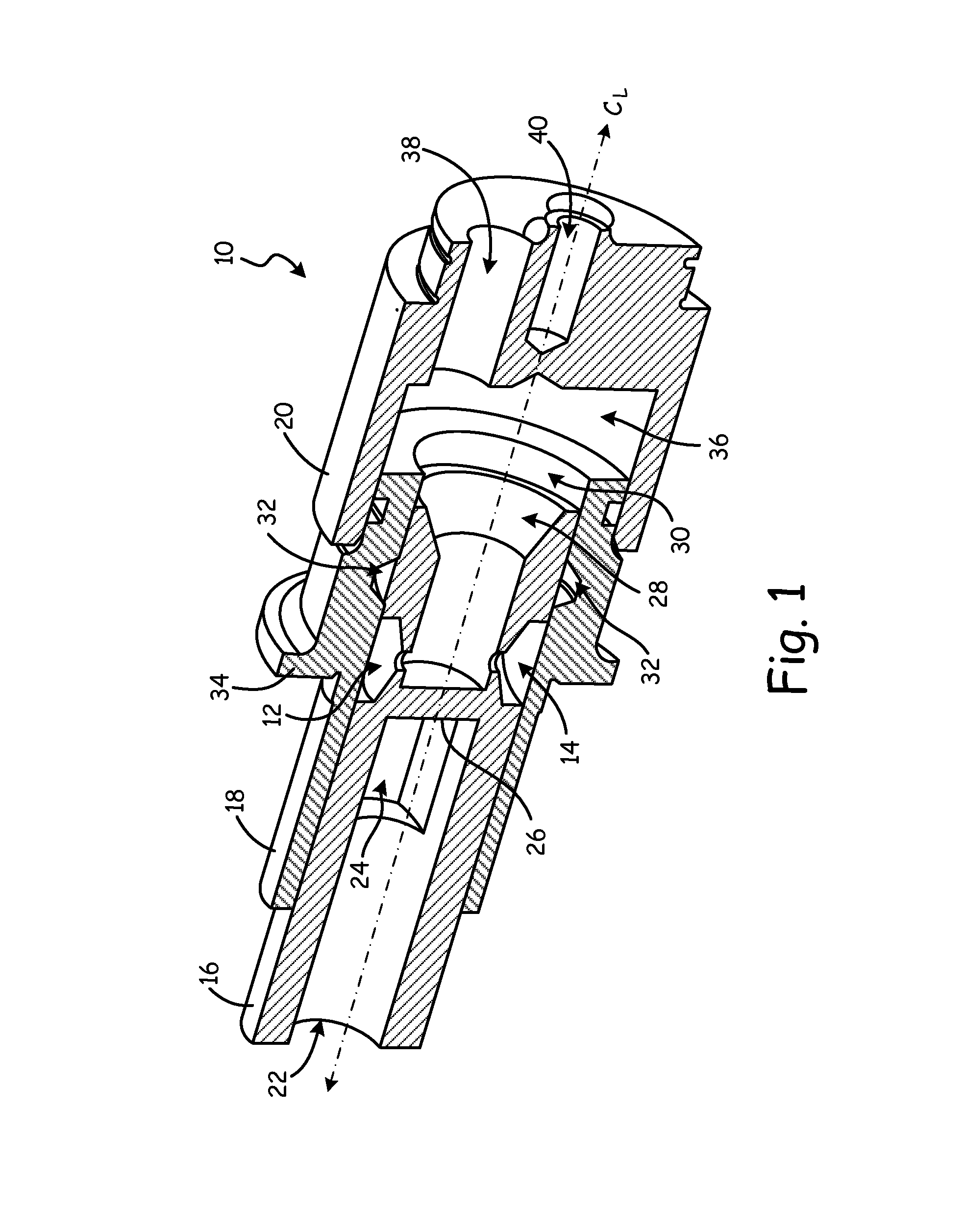
The present invention is related to fluid control valves, and in particular to the use of vortex chambers to control fluid flow. In fluid systems such as, for example, fuel systems of gas turbine engines, it is desirable to utilize valves to control fluid flow based upon fluid pressure. Prior art valves include, for example, a “keyhole” geometry on a piston of the valve. As the inlet pressure increases, the piston moves axially to align the keyhole with a fluid outlet. A desired relationship between the inlet pressure and the outlet flow rate is accomplished by varying the cross-sectional area of the keyhole in the axial direction. Traditional machining techniques generally cannot be utilized to accomplish this geometry and thus, advanced techniques such as electric discharge machining (EDM) must be implemented. This adds extra time and cost to the production of these fluid control valves. It is desirable to implement a control valve assembly that includes geometries that may be machined using traditional machining techniques. A fluid flow control apparatus includes first and second bodies, an inlet, and an outlet. The first body includes a slot, and the second body includes a vortex chamber. The second body is moveable relative to the first body to align the slot and the vortex chamber. The vortex chamber includes a chamber inlet section, an orifice, and a tapered section that has a frustoconical shape and tapers from the chamber inlet section to the orifice. The chamber inlet section is in fluid communication with the slot when the vortex chamber is aligned with the slot. The inlet is in fluid communication with the slot, and the outlet is in fluid communication with the orifice. A fluid control valve utilizes vortex chambers to control a fluid flow rate through the valve. In an embodiment, a fluid control valve includes a piston that receives a fluid at an inlet pressure. The fluid moves the piston axially relative to a sleeve. The sleeve includes a slot that is in fluid communication with the inlet. The piston includes a vortex chamber that aligns with the slot to provide the fluid to an outlet. The vortex chamber has a chamber inlet and an outlet orifice. The shape of the chamber is frustoconical and tapers from the chamber inlet to the outlet orifice. A variable flow rate is achieved such that the flow rate is greatest when the slot is directly aligned with the outlet orifice. Sleeve 18 receives piston 16 within bore 30. Fluid enters piston 16 through inlet 22. This fluid may be, for example, fuel from a reservoir for a gas turbine engine fuel system. This fluid has an inlet fluid pressure that applies an axial force upon end wall 26. Piston 16 moves axially within sleeve 18 along centerline CLbased upon this inlet fluid pressure. Slot 24 is in fluid communication with slot 32 and provides the fluid to slot 32 at the inlet pressure. Slot 32 is annular and extends around the entire circumference of sleeve 18. At low inlet fluid pressures, slot 32 is not in fluid communication with vortex chambers 12 and 14, and thus, no fluid flows through the vortex chambers to outlet 28. As the inlet pressure of the fluid within inlet 22 increases, piston 16 moves such that vortex chambers 12 and 14 move axially toward annular slot 32. This may be accomplished using any method, such as, for example, a spring (such as spring 43 shown in Vortex chamber 12 has a generally cylindrical inlet portion, a tapered portion, and an outlet orifice. The tapered portion tapers, or narrows, from the inlet portion to the outlet orifice. This cause fluid to swirl within chamber 12 when slot 32 is in fluid communication with chamber 12, but axially offset from the outlet orifice. The further the axial offset between slot 32 and the orifice, the greater the fluid swirl created within vortex chamber 12. The greater the fluid swirl in vortex chamber 12, the lower the fluid flow exiting from chamber 12. Therefore, the fluid flow rate at outlet 28 can be controlled based upon the axial offset between slot 32 the outlet orifice of vortex chamber 12. Vortex chamber 14, or any other vortex chamber included on piston 16 includes a similar geometry. This geometry allows vortex chambers 12 and 14 to be machined using traditional machining tools that include, for example, rotary cutting tools such as end mills or drill bits. As illustrated in In the embodiment shown in In the embodiment shown in With continued reference to Face seal assembly 60 may be a part of a fluid control valve and includes a fluid inlet and a fluid outlet (not shown). The fluid inlet is in fluid communication with slot 68. The fluid outlet is in fluid communication with orifices 76 Body 64 is rotatable relative to body 66 (illustrated as a clockwise motion) to align slot arm ends 72 The following are non-exclusive descriptions of possible embodiments of the present invention. A fluid flow control apparatus includes, among other possible things: first and second bodies, an inlet, and an outlet. The first body includes a slot, and the second body includes a vortex chamber. The second body is moveable relative to the first body to align the slot and the vortex chamber. The vortex chamber includes a chamber inlet section and an orifice. The chamber inlet section is in fluid communication with the slot when the vortex chamber is aligned with the slot. The inlet is in fluid communication with the slot, and the outlet is in fluid communication with the orifice. A further embodiment of the foregoing fluid flow control apparatus, wherein the vortex chamber further includes a tapered section that has a frustoconical shape and tapers from the chamber inlet to the orifice. wherein the first body is a sleeve oriented annularly about a centerline, and wherein the second body is a piston oriented annularly about the centerline. A further embodiment of any of the foregoing fluid flow control apparatuses, wherein the piston is received within a bore of the sleeve. A further embodiment of any of the foregoing fluid flow control apparatuses, wherein the slot is an annular slot that extends the full circumference of the sleeve. A further embodiment of any of the foregoing fluid flow control apparatuses, wherein the piston includes a second vortex chamber, and wherein the first and second vortex chambers are evenly spaced circumferentially about the piston. A further embodiment of any of the foregoing fluid flow control apparatuses, wherein the first body and the second body form a face seal, and wherein the first body and the second body are annular bodies that extend radially outward from a centerline. A further embodiment of any of the foregoing fluid flow control apparatuses, wherein the slot extends axially through the first body and comprises a plurality of slot arms that extend radially outward from the centerline. A further embodiment of any of the foregoing fluid flow control apparatuses, wherein the first vortex chamber is one of a plurality of vortex chambers in the second body, and wherein the second body is moveable relative to the first body to align each of the plurality of slot arms with a respective one of the plurality of vortex chambers. A fluid control valve includes, among other things: a sleeve, and a piston. The sleeve is oriented annularly about a centerline and includes an annular slot. The piston is oriented annularly about the centerline and includes an inlet, a first vortex chamber, and an outlet. The inlet is in fluid communication with the annular slot. The first vortex chamber includes a chamber inlet section, and an orifice. The outlet is in fluid communication with the orifice. The piston is moveable axially to align the annular slot with the first vortex chamber such that the chamber inlet section is in fluid communication with the annular slot. A further embodiment of the foregoing fluid control valve, wherein the first vortex chamber further includes a tapered section that has a frustoconical shape and tapers from the chamber inlet to the orifice. A further embodiment of any of the foregoing fluid control valves, wherein the piston is received within a bore of the sleeve. A further embodiment of any of the foregoing fluid control valves, wherein annular slot extends the full circumference of the sleeve. A further embodiment of any of the foregoing fluid control valves, wherein the piston includes a second vortex chamber, and wherein the first and second vortex chambers are evenly spaced circumferentially about the piston. While the invention has been described with reference to an exemplary embodiment(s), it will be understood by those skilled in the art that various changes may be made and equivalents may be substituted for elements thereof without departing from the scope of the invention. In addition, many modifications may be made to adapt a particular situation or material to the teachings of the invention without departing from the essential scope thereof. Therefore, it is intended that the invention not be limited to the particular embodiment(s) disclosed, but that the invention will include all embodiments falling within the scope of the appended claims. A fluid flow control apparatus includes first and second bodies, an inlet, and an outlet. The first body includes a slot, and the second body includes a vortex chamber. The second body is moveable relative to the first body to align the slot and the vortex chamber. The vortex chamber includes a chamber inlet section, an orifice, and a tapered section that has a frustoconical shape and tapers from the chamber inlet section to the orifice. The chamber inlet section is in fluid communication with the slot when the vortex chamber is aligned with the slot. The inlet is in fluid communication with the slot, and the outlet is in fluid communication with the orifice. 1. A fluid flow control apparatus comprising:
a first body that includes a slot; a second body that includes a first vortex chamber, wherein the second body is moveable relative to the first body to align the slot and the first vortex chamber, and wherein the first vortex chamber comprises:
a chamber inlet section in fluid communication with the slot when the first vortex chamber is aligned with the slot; and an orifice; and an inlet in fluid communication with the slot; and an outlet in fluid communication with the orifice. 2. The fluid flow control apparatus of 3. The apparatus of 4. The apparatus of 5. The apparatus of 6. The apparatus of 7. The apparatus of 8. The apparatus of 9. The apparatus of 10. A fluid control valve comprising:
a sleeve oriented annularly about a centerline that includes an annular slot; and a piston oriented annularly about the centerline, the piston comprising:
an inlet in fluid communication with the annular slot; a first vortex chamber comprising:
a chamber inlet section; and an orifice; and an outlet in fluid communication with the orifice; and wherein the piston is moveable axially to align the annular slot with the first vortex chamber such that the chamber inlet section is in fluid communication with the annular slot. 11. The valve of 12. The valve of 13. The valve of 14. The valve of BACKGROUND
SUMMARY
BRIEF DESCRIPTION OF THE DRAWINGS
DETAILED DESCRIPTION
DISCUSSION OF POSSIBLE EMBODIMENTS