MOTOR-DRIVEN COMPRESSOR
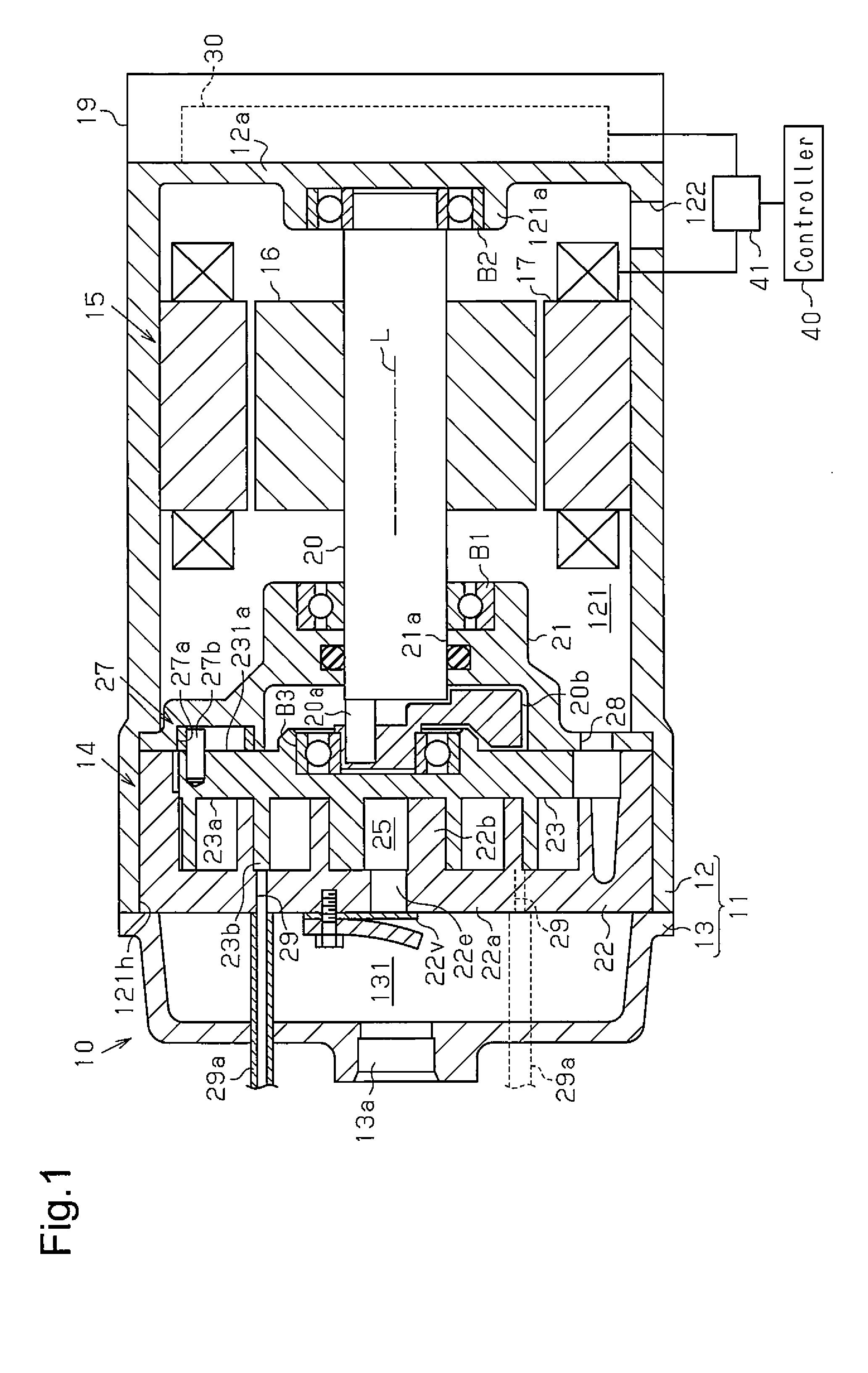
This application is based upon and claims the benefit of priority from prior Japanese Patent Application No. 2013-238097, filed on Nov. 18, 2013, the entire contents of which are incorporated herein by reference. The present invention relates to a motor-driven compressor including an injection port that draws intermediate pressure refrigerant into a compression chamber formed by the engagement of a fixed scroll and a movable scroll. Japanese Laid-Open Patent Publication No. 2003-120555 describes a motor-driven scroll compressor in which an injection pipe is connected to an injection port of a compression chamber. A vapor-liquid separator is connected to the injection pipe. The injection pipe includes a check valve. In a refrigeration cycle, the check valve opens the injection pipe during a high load operation (e.g., heating operation) and closes the injection pipe during a low load operation (e.g., cooling operation). During the high load operation of the refrigeration cycle, an intermediate pressure gaseous refrigerant separated by the vapor-liquid separator is injected into the compression chamber through the injection pipe, which is open through the check valve, and the injection port. This increases the amount of the gaseous refrigerant drawn into the compression chamber and improves the performance of the motor-driven compressor during the high load operation of the refrigerant cycle. In the motor-driven compressor, when the operation of the motor-driven compressor is stopped by stopping the rotation control of the rotor of the electric motor, the forward rotation speed of the rotor gradually decreases. When the forward rotation of the rotor stops, the residual intermediate pressure gaseous refrigerant remaining in the injection pipe is drawn through the injection port into the compression chamber. As a result, the movable scroll starts to orbit in a reverse direction, which is opposite to that when the motor-driven compressor is operated. The orbiting motion of the movable scroll in the reverse direction rotates the rotor in the reverse direction. When the reverse rotation speed of the rotor exceeds a predetermined speed, it is difficult to restart the rotation control of the rotor. For example, to restart the operation of the motor-driven compressor, there is a need to wait until the reverse rotation speed of the rotor decreases to a speed that is low enough to restart the rotation control of the rotor. Therefore, when restarting operation of the motor-driven compressor, immediate restarting of the rotor rotation control may be hindered. In this manner, the conventional motor-driven compressor cannot be smoothly restarted. It is an object of the present invention to provide a motor-driven compressor that may be smoothly restarted. A motor-driven compressor according to one aspect of the present invention includes a compression unit that includes a movable scroll, a fixed scroll, and a compression chamber formed by engagement of the movable scroll and the fixed scroll, an electric motor that includes a rotor and drives the compression unit, a motor drive circuit that drives the electric motor, an injection port that draws intermediate pressure refrigerant into the compression chamber, a controller that performs rotation control on the rotor, and a voltage detector that detects a terminal voltage of the electric motor. The compression unit compresses low pressure refrigerant drawn into the compression chamber to discharge high pressure refrigerant. The controller is configured to output a stop instruction to deactivate the rotation control of the rotor, determine a rotation condition of the rotor based on the voltage detected by the voltage detector after outputting the stop instruction, and perform, based on the determination, restart preparation control that includes outputting a lock instruction to electrically stop rotation of the rotor. Other aspects and advantages of the invention will become apparent from the following description, taken in conjunction with the accompanying drawings, illustrating by way of example the principles of the invention. The invention, together with objects and advantages thereof, may best be understood by reference to the following description of the presently preferred embodiments together with the accompanying drawings in which: One embodiment of a motor-driven compressor will now be described with reference to As shown in The motor housing 12 includes an end wall 12 The electric motor 15 includes a rotor 16 (rotating part), which rotates integrally with the rotation shaft 20, and a stator 17 (stationary part) surrounding the rotor 16. The stator 17 may be fixed to an inner surface of the motor housing 12. The compression unit 14 includes a fixed scroll 22 and a movable scroll 23. The fixed scroll 22 includes a fixed base plate 22 An eccentric shaft 20 The fixed spiral wall 22 A rotation restriction mechanism 27 is arranged between the movable base plate 23 When the electric motor 15 rotates the rotation shaft 20, the eccentric shaft 20 The motor housing 12 includes a suction opening 122. The shaft support member 21 includes a suction passage 28 communicating the motor compartment 121 and the compression chamber 25. The discharge housing 13 and the fixed base plate 22 A discharge port 22 A cover 19 is attached to the end wall 12 As shown in As shown in The pipe switching valve 51 includes a first opening 51 A discharge pipe 57 connects the discharge opening 13 A third pipe 60 connects the first expansion valve 54 and the vapor-liquid separator 56. A fourth pipe 61 connects the vapor-liquid separator 56 and the second expansion valve 55. A fifth pipe 62 connects the second expansion valve 55 and the second heat exchanger 53. A sixth pipe 63 connects the second heat exchanger 53 and the third opening 51 The vapor-liquid separator 56 is connected to the injection pipe 29 As shown in The bases of the upper arm switching elements 31 The controller 40 is configured to control rotation of the rotor. For example, the controller 40 generates a PWM signal in accordance with a carrier signal, which may be a high frequency triangular wave signal, and a voltage instruction signal, which instructs the voltage. The controller 40 uses the PWM signal to control the switching operations of the upper arm switching elements 31 A voltage detector 41 is configured to detect a terminal voltage of the electric motor 15. The voltage detector 41 is connected to, for example, the motor drive circuit 30 and the coil 15W. The voltage detector 41 provides the controller 40 with a voltage detection signal indicating the detected voltage. The controller 40 monitors the terminal voltage of the electric motor 15 based on the voltage detection signal. The controller 40 may receive a request for stopping the electric motor 15 or the motor-driven compressor 10. In this case, the controller 40 outputs a stop instruction CS to stop the rotation control of the rotor 16 and determines the rotation condition of the rotor 16 based on the voltage detected by the voltage detector 41 after outputting the stop instruction CS. The controller 40 includes a control program that performs a restart preparation control configured to output a lock instruction CL to electrically or forcibly stop the rotation of the rotor 16 based on the determination result. In the embodiment, the restart preparation control of the controller 40 includes deactivating the upper arm switching elements 31 The operation of the cooling-heating circuit 50 will now be described. When the rotor 16 rotates forward, the rotation shaft 20 causes the movable scroll 23 to orbit in the forward direction. Accordingly, the compression unit 14 performs compressing and discharging operations, and the refrigerant circulates through the cooling-heating circuit 50. The refrigerant is drawn through the suction opening 122 into the motor compartment 121. The refrigerant is drawn from the motor compartment 121 into the compression chamber 25 via the suction passage 28. The low pressure refrigerant drawn into the compression chamber 25 is compressed by the orbiting motion (discharging operation) of the movable scroll 23. The compressed refrigerant opens the discharge valve 22 During a cooling operation, the pipe switching valve 51 is switched to the first state. This communicates the first and second openings 51 The liquid refrigerant separated by the vapor-liquid separator 56 flows into the second expansion valve 55 via the fourth pipe 61. The second expansion valve 55 depressurizes the liquid refrigerant. The depressurized liquid refrigerant flows from the second expansion valve 55 into the second heat exchanger 53 via the fifth pipe 62. In the second heat exchanger 53, the liquid refrigerant is vaporized by exchanging heat with the air in the passenger compartment. This cools the air in the passenger compartment. The vaporized refrigerant flows from the second heat exchanger 53 back to the motor compartment 121 via the sixth pipe 63, the third and fourth openings 51 The gaseous refrigerant separated by the vapor-liquid separator 56 flows into the injection pipe 29 During a heating operation, the pipe switching valve 51 is switched to the second state. This communicates the first and third openings 51 The liquid refrigerant separated by the vapor-liquid separator 56 flows into the first expansion valve 54 via the third pipe 60. The first expansion valve 54 depressurizes the liquid refrigerant. The depressurized liquid refrigerant flows from the first expansion valve 54 into the first heat exchanger 52 via the second pipe 59. In the first heat exchanger 52, the liquid refrigerant is vaporized by exchanging heat with the external air. The vaporized refrigerant flows from the first heat exchanger 52 back to the motor compartment 121 via the first pipe 58, the second and fourth openings 51 The gaseous refrigerant separated by the vapor-liquid separator 56 flows into the injection pipe 29 The intermediate pressure gaseous refrigerant is delivered to the compression chamber 25 through the injection ports 29. This increases the amount of the gaseous refrigerant drawn into the compression chamber 25 and improves the performance of the motor-driven compressor 10 during a high load operation, such as a heating operation. The operation of the embodiment will now be described. When the operation of the motor-driven compressor 10 is stopped, the controller 40 provides the motor drive circuit 30 with the stop instruction CS to stop the rotation control of the rotor 16. In response to the stop instruction CS, the motor drive circuit 30 stops the application of a drive voltage. This decreases the forward rotation speed of the rotor 16. When the forward rotation of the rotor 16 stops, the residual intermediate pressure gaseous refrigerant remaining in the injection pipe 29 As shown in For example, when the controller 40 determines that the rotor 16 is rotating reversely, the controller 40 of the present embodiment outputs the lock instruction CL (restart preparation control) to electrically or forcibly stop the rotor 16. For example, the controller 40 deactivates the upper arm switching elements 31 Then, the controller 40 restarts the rotation control of the rotor 16 and controls the switching operations of the upper arm switching elements 31 The present embodiment has the advantages described below. (1) The controller 40 outputs the stop instruction CS to stop the rotation control of the rotor 16 and determines the rotation condition of the rotor 16 based on the voltage detected by the voltage detector 41 after the output of the stop instruction CS. The controller 40 performs the restart preparation control configured to output the lock instruction CL to electrically or forcibly stop the rotation of the rotor 16 based on the determination result. In this manner, the controller 40 may electrically or forcibly stop the rotation of the rotor 16 by performing the restart preparation control. This quickly stops the rotation of the rotor 16. Thus, the motor-driven compressor 10 may be smoothly restarted. (2) The restart preparation control of the controller 40 includes outputting the lock instruction CL when the controller 40 determines that the rotor 16 is rotating reversely based on the voltage detected by the voltage detector 41. In this manner, even when the rotor 16 rotates reversely, the controller 40 may electrically or forcibly stop the reverse rotation of the rotor 16 by performing the restart preparation control. This smoothly restarts the motor-driven compressor 10. (3) The restart preparation control of the controller 40 includes outputting the lock instruction CL configured to deactivate the upper arm switching elements 31 It should be apparent to those skilled in the art that the present invention may be embodied in many other specific forms without departing from the scope of the invention. Particularly, it should be understood that the present invention may be embodied in the following forms. The restart preparation control of the controller 40 may include outputting the lock instruction CL when the controller 40 determines the rotation of the rotor 16 is stopped based on the voltage detected by the voltage detector 41. In this case, the controller 40 performs the restart preparation control when the rotor 16 is being stopped. Thus, the rotor 16 does not rotate reversely. This modified example allows for reduction in the load used to electrically stop the rotor 16 as compared to when the controller 40 performs the restart preparation control while the rotor 16 is rotating. It is desirable that the residual intermediate pressure gaseous refrigerant be eliminated from the injection pipe 29 The restart preparation control of the controller 40 may include outputting the lock instruction CL configured to activate the upper arm switching elements 31 The restart preparation control of the controller 40 may include outputting the lock instruction CL configured to supply a predetermined current to the electric motor 15. In this case, a current value that sufficiently stops the rotation of the rotor 16 is determined in advance through experiments or simulations. The current value is stored in the controller 40 in advance. The controller 40 may determine the rotation condition of the rotor 16 based on a frequency of the voltage detected by the voltage detector 41. More specifically, when the voltage detected by the voltage detector 41 has a frequency less than 30 Hz, the controller 40 determines that the rotation speed of the rotor 16 is low enough to restart the rotation control of the rotor 16. That is, the controller 40 determines that the rotor 16 is not rotating reversely. When the voltage detected by the voltage detector 41 has a frequency greater than or equal to 30 Hz, the controller 40 determines that the rotation speed of the rotor 16 is not low enough to restart the rotation control of the rotor 16. That is, the controller 40 determines that the rotor 16 is rotating reversely. The voltage detector 41 may be electrically connected between two of the coils 15U, 15V, and 15W. In this case, the voltage used to determine that the rotor 16 has stopped is more easily obtained than when, for example, the voltage detector 41 is electrically connected between the motor drive circuit 30 and the coil 15W. The voltage detector 41 may start detecting the voltage after the controller 40 outputs the stop instruction CS. The voltage detector 41 may stop detecting the voltage after the controller 40 outputs the lock instruction CL. This reduces the operation frequency of the voltage detector 41 as compared to when the voltage detector 41 constantly detects the voltage. The injection ports 29 are not limited to a particular shape. For example, an elliptic shape corresponding to the spiral shape of the fixed spiral wall 22 The movable base plate 23 The injection ports 29 may be omitted, and the movable base plate 23 The cover 19 may be attached to a circumferential wall of the motor housing 12. The motor drive circuit 30 may be accommodated between the circumferential wall of the motor housing 12 and the cover 19. The compression unit 14 may be, for example, of a piston type or a vane type. The motor-driven compressor 10 does not have to be installed in a vehicle. The motor-driven compressor 10 may be used with an air-conditioning system other than that for a vehicle. The controller 40 may include computer-readable media for carrying or having computer-executable instructions or data structures stored thereon. Such computer-readable media can be any available media that can be accessed by a general purpose or special purpose computer. By way of example, and not limitation, such computer-readable media can comprise RAM, ROM, EEPROM, CD-ROM or other optical disk storage, magnetic disk storage or other magnetic storage devices, or any other medium which can be used to carry or store desired program code means in the form of computer-executable instructions or data structures and which can be accessed by a general purpose or special purpose computer. The above description is intended to be illustrative, and not restrictive. For example, the above-described examples (or one or more aspects thereof) may be used in combination with each other. Other embodiments can be used, such as by one of ordinary skill in the art upon reviewing the above description. Also, in the above Detailed Description, various features may be grouped together to streamline the disclosure. This should not be interpreted as intending that an unclaimed disclosed feature is essential to any claim. Rather, inventive subject matter may lie in less than all features of a particular disclosed embodiment. Thus, the following claims are hereby incorporated into the Detailed Description, with each claim standing on its own as a separate embodiment. The scope of the invention should be determined with reference to the appended claims, along with the full scope of equivalents to which such claims are entitled. A motor-driven compressor includes a compression unit that includes movable and fixed scrolls and a compression chamber, an electric motor that includes a rotor and drives the compression unit, a motor drive circuit that drives the electric motor, an injection port that draws intermediate pressure refrigerant into the compression chamber, a controller that performs rotation control on the rotor, and a voltage detector that detects a terminal voltage of the electric motor. The compression unit compresses low pressure refrigerant drawn into the compression chamber to discharge high pressure refrigerant. The controller is configured to output a stop instruction to deactivate the rotation control of the rotor, determine a rotation condition of the rotor based on the voltage detected by the voltage detector after outputting the stop instruction, and perform, based on the determination, restart preparation control that includes outputting a lock instruction to electrically stop rotation of the rotor. 1. A motor-driven compressor comprising:
a compression unit including a movable scroll, a fixed scroll, and a compression chamber formed by engagement of the movable scroll and the fixed scroll, wherein the compression unit compresses low pressure refrigerant drawn into the compression chamber to discharge high pressure refrigerant; an electric motor including a rotor, wherein the electric motor drives the compression unit; a motor drive circuit that drives the electric motor; an injection port that draws intermediate pressure refrigerant into the compression chamber; a controller that performs rotation control on the rotor; and a voltage detector that detects a terminal voltage of the electric motor, wherein the controller is configured to
output a stop instruction to deactivate the rotation control of the rotor, determine a rotation condition of the rotor based on the voltage detected by the voltage detector after outputting the stop instruction, and perform, based on the determination, restart preparation control that includes outputting a lock instruction to electrically stop rotation of the rotor. 2. The motor-driven compressor according to 3. The motor-driven compressor according to 4. The motor-driven compressor according to the motor drive circuit includes an upper arm switching element and a lower arm switching element, and the restart preparation control of the controller includes outputting the lock instruction configured to activate a first element that is one of the upper arm switching element and the lower arm switching element so that the first element performs a switching operation and to deactivate a second element that is the other one of the upper arm switching element and the lower arm switching element so that the second element does not perform a switching operation. 5. The motor-driven compressor according to determining a rotation condition of the rotor based on an amplitude of the voltage detected by the voltage detector, and outputting the lock instruction based on the determination. 6. The motor-driven compressor according to determining the rotation condition of the rotor based on a frequency of the voltage detected by the voltage detector, and outputting the lock instruction based on the determination. 7. The motor-driven compressor according to 8. The motor-driven compressor according to 9. A controller for a motor-driven compressor, wherein the motor-driven compressor includes a compression unit including a movable scroll, a fixed scroll, and a compression chamber formed by engagement of the movable scroll and the fixed scroll, wherein the compression unit compresses low pressure refrigerant, which is drawn into the compression chamber, to discharge high pressure refrigerant, an electric motor that drives the compression unit and includes a rotor, a motor drive circuit that drives the electric motor in accordance with an instruction from the controller, an injection port that draws intermediate pressure refrigerant into the compression chamber, and a voltage detector that detects a terminal voltage of the electric motor, the controller comprising:
a processor configured to
output a stop instruction to stop rotation control of the rotor; determine a rotation condition of the rotor based on the voltage detected by the voltage detector after outputting the stop instruction; and perform, based on the determination, a restart preparation control, which includes outputting a lock instruction to electrically stop rotation of the rotor. 10. A method for controlling a motor-driven compressor, wherein the motor-driven compressor includes a compression unit including a movable scroll, a fixed scroll, and a compression chamber formed by engagement of the movable scroll and the fixed scroll, wherein the compression unit compresses low pressure refrigerant, which is drawn into the compression chamber, to discharge high pressure refrigerant, an electric motor including a rotor that drives the compression unit, a motor drive circuit that drives the electric motor in accordance with an instruction from the controller, an injection port that draws an intermediate pressure refrigerant into the compression chamber, and a voltage detector that detects a terminal voltage of the electric motor, the method comprising:
providing the motor drive circuit with a stop instruction to stop rotation control of the rotor; determining a rotation condition of the rotor based on the voltage detected by the voltage detector after outputting the stop instruction; and performing, based on the determination, performing a restart preparation control, which includes outputting a lock instruction to electrically stop rotation of the rotor. CROSS-REFERENCE TO RELATED APPLICATIONS
BACKGROUND OF THE INVENTION
SUMMARY OF THE INVENTION
BRIEF DESCRIPTION OF THE DRAWINGS
DESCRIPTION OF THE EMBODIMENTS