Mountable Device For Dispensing Heated Adhesive
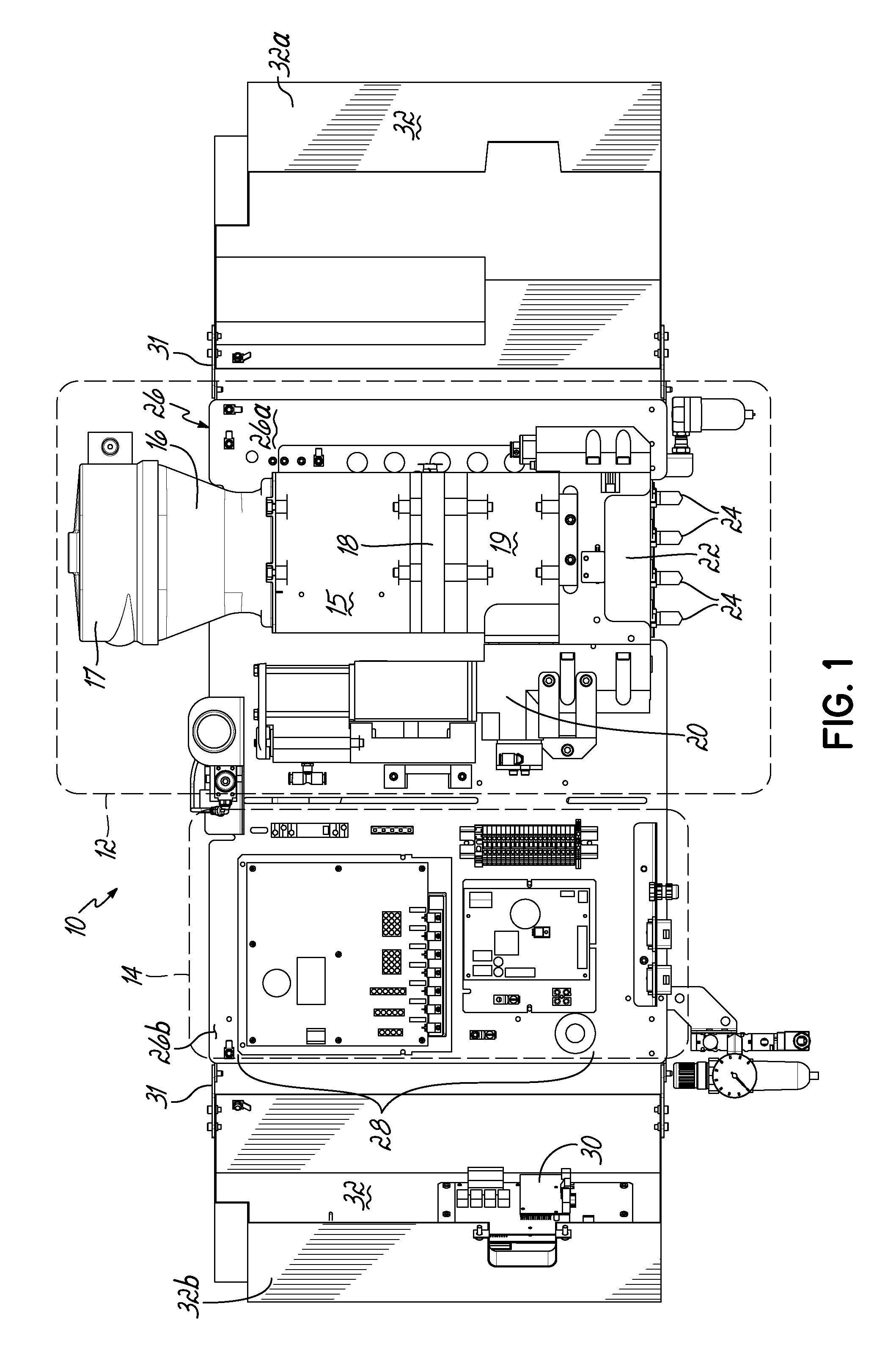
This application is a continuation of U.S. patent application Ser. No. 13/659,291 filed Oct. 24, 2012 (pending), which claims the benefit of U.S. Provisional Patent Application Ser. No. 61/552,961, filed on Oct. 28, 2011 (expired), the disclosures of which are incorporated by reference herein in their entirety. This application is also related to International Patent Application No. PCT/US2012/061899 filed Oct. 25, 2012 (expired). The present invention generally relates to liquid dispensing devices used for a variety of purposes, and more particularly to dispensing devices for heated adhesives. A conventional dispensing device for supplying heated adhesive (i.e., a hot-melt adhesive dispenser) generally includes an inlet for receiving adhesive materials, a heated grid in communication with the inlet which heats the adhesive materials, an outlet in communication with the heated grid, which receives the heated adhesive from the heated grid, a hose connected to the outlet for directing the dispensation of the heated adhesive, and a pump in communication with the heated grid and outlet for driving and controlling the dispensation of the heated adhesive through the outlet. Furthermore, conventional dispensing devices generally includes a controller (e.g., a processor and a memory), input controls electrically connected to the controller to facilitate user interface with the dispensing device, and the controller is in communication with the pump, heated grid, and/or other components of the device, such that the controller controls the dispensation of the heated adhesive. Conventional hot-melt adhesive dispensers typically operate at elevated temperatures, such as about 350° F. The high temperatures are generally required to sufficiently heat received adhesive materials prior to dispensing the heated adhesive. Various measures are typically taken to insulate a hot-melt adhesive dispenser to make the dispenser more efficient at heating the adhesive and also in consideration of operator safety. Conventional hot-melt dispensers also generally have a large footprint (i.e., occupied space), and conventional dispensers typically rest on horizontal surfaces (i.e., a floor or table) in a workspace utilizing valuable workspace. In addition, while insulating the hot-melt adhesive dispenser is desirable with regard to thermal efficiency, the resulting temperatures within the housing of the dispenser may lead to reliability issues of various components of the dispenser. For reasons such as these, an improved hot-melt adhesive dispenser design would be desirable. In accordance with one aspect, a device for dispensing adhesive may include a vertically oriented mounting plate having front and back sides. The dispenser also includes a melter subassembly including an adhesive manifold, a heated grid (i.e., a heater), and a pump coupled to the mounting plate. In some embodiments, a lift-off hinge removably and rotatably couples the melter subassembly to the mounting plate. The melter subassembly may also include an inlet for receiving adhesive material, and an outlet for dispensing heated adhesive material, and the melter subassembly heats adhesive material received from the inlet and controllably dispenses heated adhesive material through the outlet. In a second aspect, a dispenser may include a control subassembly coupled to the mounting plate and spaced apart from the melter subassembly. The control subassembly includes a controller (e.g., an integrated circuit, a processor, a memory) where the control subassembly is in communication with one or more components of the melter subassembly such that the control subassembly communicates with the one or more components of the melter subassembly to thereby control operation of the one or more components of the melter subassembly. In addition, the dispenser may include a subassembly cover coupled to the mounting plate. The subassembly cover may be moved between an open condition and a closed condition, such that in the closed condition the subassembly cover covers the melter subassembly, and may further cover the control subassembly. In the closed condition, the subassembly cover thermally insulates the melter subassembly from the control subassembly. When in the open condition, the melter subassembly and/or the control subassembly are exposed for access by a user of the device. Hence, when in the closed condition, the subassembly cover reduces heat transfer between the melter subassembly and the control subassembly. Thermally insulating the melter subassembly from the control subassembly may extend the life of the control subassembly, allow the melter subassembly to operate at higher temperatures, and/or give rise to other such advantages. In some embodiments, the subassembly cover may comprise one or more additional portions, where if two or more portions are included, the portions may be coupled to the mounting plate at different positions. In addition, in an aspect of some embodiments, the subassembly cover may include one or more insulation elements mounted to the subassembly cover, and/or one or more thermal vents passing through one or more surfaces of the subassembly cover. Advantages over conventional hot-melt adhesive dispensers may be realized in dispensers consistent with the invention. For example, a smaller foot-print as compared to conventional dispensers may be realized. Advantageously, embodiments of the invention may be mounted to a vertical plane, which may thereby improve integration with workspaces utilizing hot-melt adhesive dispensers. In addition, the control subassembly and melter subassembly of embodiments of the invention may be spaced apart and thereby reducing heat transfer between the control subassembly and the melter subassembly. As a result of the relatively smaller volume of a dispenser in accordance with the principles of the present invention, faster warm-up times from a cold start are possible. Moreover, dispenser embodiments that do not have a tank facilitate reduced adhesive dwell times, thereby eliminating or minimizing heat degradation of the adhesive. Various additional features and advantages of the invention will become more readily apparent to those of ordinary skill in the art upon review of the following detailed description of the illustrative embodiments, taken in conjunction with the accompanying drawings. The accompanying drawings, which are incorporated in and constitute a part of this specification, illustrate embodiments of the invention and, together with a general description of the invention given above, and the detailed description below, serve to explain one or more embodiments of the invention. It should be understood that the appended drawings may not necessarily be to scale, presenting a somewhat simplified representation of various preferred features illustrative of the basic principles of embodiments of the invention. The specific features consistent with embodiments of the invention disclosed herein, including, for example, specific dimensions, orientations, locations, sequences of operations and shapes of various illustrated components, will be determined in part by the particular intended application, use and/or environment. Certain features of the illustrated embodiments may have been enlarged or distorted relative to others to facilitate visualization and clear understanding. With reference to The hopper 15 is smaller than the hoppers of conventional melters. The heated grid 18 is sized or matched to the pellet size of hotmelt adhesive. By utilizing a small hopper 15 and rapidly heating the adhesive with the heated grid 18, the throughput of adhesive may approximate that of much larger sized melters. A cyclone 17 is in communication with the inlet 16, such that adhesive materials may be loaded into the cyclone 17, and the cyclone 17 facilitates feeding adhesive materials into the inlet 16. While cyclone 17 is provided herein for feeding adhesive materials into inlet 16, it will be appreciated that various other structure could alternatively be used to feed adhesive materials into inlet 16, including structure for feeding a supply of adhesive materials into an inlet such as a tank, a tube, a pressurized hose, and/or a funnel, for example. A heated adhesive reservoir 19 in communication with the heated grid 18 holds heated adhesive received from the heated grid 18 for dispensing. A pump 20 and a manifold 22 in communication with the reservoir 19 and outlet(s) 24 controllably dispense heated adhesive from the reservoir 19 through the outlet 24. The pump 20 may be a piston pump, and may be mounted vertically or parallel to the centerline of the hopper 15 and heated grid 18. Melter subassembly 12 may be coupled to a vertically oriented mounting plate 26, which will be described in more detail below. The control subassembly 14 is coupled to the mounting plate 26 adjacent the melter subassembly 12, such that the melter subassembly 12 and control subassembly 14 are spaced apart. In some embodiments, the melter assembly 12 is proximate a first terminal end 26 With continued reference to Referring now to According to principles of the present invention, a hot melt adhesive dispenser is provided. Advantageously, the dispenser may include a vertically oriented mounting plate coupled to a melter subassembly and a control subassembly such that the dispenser may be mounted on a vertical surface and/or casters. Moreover, the dispenser may include a subassembly cover configured to substantially thermally isolate the melter subassembly and the control subassembly and thereby reduce heat transfer between the melter subassembly and the control subassembly. As such, dispensers consistent with embodiments of the invention may overcome limitations of conventional systems which typically include large device footprints due to the integrated nature of the components of the conventional systems. Moreover, dispensers according to principles of the invention may improve reliability of electrical components included in the control subassembly by, for example, reducing heat transfer from the melter subassembly to the control subassembly. Furthermore, a dispenser may include a melter subassembly rotatably and removably coupled to the mounting plate, such that the melter subassembly may be rotated relative to the mounting plate to facilitate access to components of the melter subassembly, such that the melter subassembly may be removed from the device for repair, maintenance, and/or repair. While the invention has been illustrated by a description of various embodiments and examples, and while these embodiments have been described in considerable detail, it is not the intention of the applicants to restrict or in any other way limit the scope of the appended claims to such detail. The various features shown and described herein may be used alone or in any combination. Additional advantages and modifications will readily appear to those skilled in the art. Thus, the invention in its broader aspects is therefore not limited to the specific details, representative apparatus and method, and illustrative example shown and described. Accordingly, departures may be made from such details without departing from the spirit or scope of applicants' general inventive concept. A device for dispensing a heated liquid, such as a hot melt adhesive, includes a vertically oriented mounting plate; a melter subassembly including an adhesive manifold, a heater, and a pump adapted to dispense the heated liquid; a control subassembly adapted to control one or more components of the melter subassembly; and a subassembly cover coupled to the mounting plate for movement between an open condition and a closed condition. The subassembly cover thermally insulates the melter assembly from the control assembly when in the closed condition. 1. An apparatus for dispensing adhesive, comprising:
a melter subassembly couplable to a support, the melter subassembly including an adhesive manifold, a heater, and a pump disposed in a generally vertical arrangement; and a control subassembly independently mountable relative to the melter subassembly and having a controller in communication with the melter subassembly. 2. The apparatus of 3. The apparatus of a melter subassembly cover having an open condition and a closed condition, the melter subassembly cover thermally insulating the melter subassembly from the control subassembly when in the closed condition. 4. The apparatus of 5. The apparatus of a hopper for receiving unmelted adhesive, and communicating with the heater; and a cyclone in communication with the hopper and feeding solid adhesive to the hopper. 6. The apparatus of 7. The apparatus of CROSS REFERENCE
TECHNICAL FIELD
BACKGROUND
SUMMARY
BRIEF DESCRIPTION OF THE DRAWINGS
DETAILED DESCRIPTION