RIVET STUD BOLT AND PANEL JOINT STRUCTURE OF THE SAME
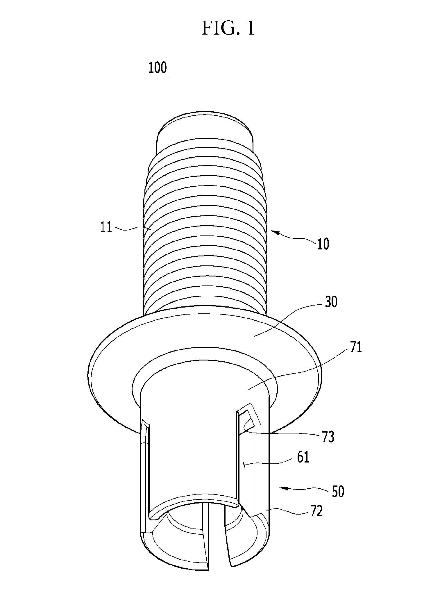
This application claims priority to and the benefit of Korean Patent Application No. 10-2014-0015080 filed in the Korean Intellectual Property Office on Feb. 10, 2014, and Korean Patent Application No. 10-2014-0032293 filed in the Korean Intellectual Property Office on Mar. 19, 2014, the entire contents of which are incorporated herein by reference. (a) Field of the Invention The present invention relates to a stud bolt. More particularly, the present invention relates to a rivet stud bolt (RSB) for mechanically assembling an element to a base such as a panel, and a panel joint structure with the rivet stud bolt. (b) Description of the Related Art In automotive industries, a weld bolt, a weld nut, a stud bolt, and so on are applied to mount an element such as an engine, a transmission, a steering system, and so on to a base such as a vehicle panel, a frame, and so on. Generally, a stud bolt including a bolt portion and a flange is connected to the base by welding the flange to the base. For example, the flange of the stud bolt is instantaneously melted by arc discharge then the flange is welded to the base. However, in arc welding, soot is generated near the welding portion of the base and the flange portion, positions of the stud bolt are various, deformation of the welded portion may be generated, and the stud bolt may be easily disassembly due to weak connecting strength. For overcoming the drawbacks described above, a stud bolt including a bolt portion, a flange and a rivet portion integrally formed for mechanical connection has been developed, for example, U.S. Pat. No. 7,287,944. In mechanical connection using the stud bolt, an assembling hole is formed to a base, the rivet portion is inserted into the assembling hole, and then the rivet portion is plastically deformed by pressing the stud bolt to connect the stud bolt to the base. In this case, the rivet portion shaped as a hollow cylinder is plastically deformed to fit the base. For example, the rivet portion of the rivet stud bolt penetrates the hole of the base by a punch of a setting tool, is outwardly deformed by a forming groove of a die (also called an anvil), and then is press-fitted to the base. However, the plastically deformed portion is deformed as a ring so that the connection strength of the rivet portion is not sufficient. Therefore, the stud bolt may be rotated. Also, since the end of the rivet portion is deformed as an annular edge, the setting tool requires a heavy load for plastically deforming the rivet portion. The above information disclosed in this Background section is only for enhancement of understanding of the background of the invention and therefore it may contain information that does not form the prior art that is already known in this country to a person of ordinary skill in the art. The present invention has been made in an effort to provide a rivet stud bolt for mechanically assembling an element to a base and a panel joint structure with the rivet stud bolt having advantages of enhancing joining strength of joining objects, and reducing a joining load of a setting tool for plastically deforming a rivet portion. A rivet stud bolt according to exemplary embodiments of the present invention integrally joins an element to a base such as at least one panel. In one or more exemplary embodiments, a rivet stud bolt may include a bolt portion to which the panel is assembled, a flange integrally formed to an end of the bolt portion, and a rivet portion integrally connected to the flange, in which at least two slits are formed, and the rivet portion is plastically deformed and connected to the panel. In one or more exemplary embodiments, the rivet portion is formed as a cylinder shape shank, the rivet portion includes a connecting end connected to the flange and a free end being an opposite end of the connecting end, and the slits are extended from the free end to the connecting end of the rivet portion. In one or more exemplary embodiments, a length of the slit is shorter than that of the rivet portion, and the slits are circumferentially disposed at the rivet portion at a constant interval. In one or more exemplary embodiments, the rivet portion includes a first portion integrally connected to the flange and having a circular cross-section, and a plurality of second portions integrally connected to the first portion and disposed between the slits. In one or more exemplary embodiments, the slit is provided with a triangular groove at the first portion, and the groove is connected to a space between the second portions. In one or more exemplary embodiments, a rotation preventing portion is formed to an edge of the flange. In one or more exemplary embodiments, the rotation preventing portion is formed as teeth continuously formed to the edge of the flange. In one or more exemplary embodiments, the rotation preventing portion includes at least one straight portion formed to the edge of the flange. In one or more exemplary embodiments, the rotation preventing portion includes a plurality of protrusion formed to the edge of the flange. A panel joint structure according to exemplary embodiments of the present invention may mount an element to at least one panel with the rivet stud bolt according to exemplary embodiments of the present invention. In one or more exemplary embodiments, the rivet portion of the rivet stud bolt is inserted into an assembling hole formed to the panel, and the rivet portion is plastically deformed and is press-fitted to a plurality of jointing portion of the panel through the slits. In one or more exemplary embodiments, the rivet portion penetrates the assembling hole, is outwardly plastically deformed, supports the panel, and is connected to the panel as a staple shape. In one or more exemplary embodiments, the rivet portion is plastically deformed and press-fitted to a plurality of jointing portion of a lower portion of the panel through the slits. In one or more exemplary embodiments, a rotation preventing portion is formed to an edge of the flange. A panel joint structure according to exemplary embodiments of the present invention may mount an element to at least one panel with the rivet stud bolt according to exemplary embodiments of the present invention. In one or more exemplary embodiments, the rivet portion of the rivet stud bolt penetrates the panel, is outwardly plastically deformed, and is press-fitted to a plurality of jointing portion of the panel through the slits. In one or more exemplary embodiments, the rivet portion connects a portion of the panel corresponding to the inner space with other portions of the panel corresponding to the slits. In one or more exemplary embodiments, a rotation preventing portion is formed to an edge of the flange. A panel joint structure according to exemplary embodiments of the present invention may mount an element to at least one panel with the rivet stud bolt according to exemplary embodiments of the present invention. In one or more exemplary embodiments, the rivet portion of the rivet stud bolt is outwardly plastically deformed, and is press-fitted to a plurality of jointing portion of the panel through the slits without complete penetration of the panel; and the rivet portion connects a portion of the panel corresponding to the inner space with other portions of the panel corresponding to the slits. In one or more exemplary embodiments, a protruding portion is formed to a lower surface of the panel corresponding to the rivet portion. In one or more exemplary embodiments, a rotation preventing portion is formed to an edge of the flange. A panel joint structure according to exemplary embodiments of the present invention may mount an element to at least two panels with the rivet stud bolt according to exemplary embodiments of the present invention. In one or more exemplary embodiments, the rivet portion of the rivet stud bolt penetrates upper panels except for a lowest panel, is outwardly plastically deformed, and is press-fitted to a plurality of jointing portions of the lowest panel through the slits, and the rivet portion connects a portion of the upper panels corresponding to the inner space with other portions of the upper panels corresponding to the slits. In one or more exemplary embodiments, the panels are integrally assembled by the rivet portion. In one or more exemplary embodiments, a protruding portion is formed to a lower surface of the lowest panel corresponding to the rivet portion. In one or more exemplary embodiments, a rotation preventing portion is formed to an edge of the flange. According to the exemplary embodiments of the present invention, since a plurality of slits are formed to a rivet portion, joining strength of a stud bolt with a base may be enhanced and rotation of the stud bolt may be prevented. According to the exemplary embodiments of the present invention, since a plurality of slits are formed to a rivet portion, a joining load applied to the stud bolt by a joining system may be reduced, operation stability of the joining system may be enhanced, and a quantity of materials for manufacturing the stud bolt may be reduced. In some exemplary embodiments, since an assembling hole is not required in a panel or a base, productivity may be improved, manufacturing processes may be simplified, and manufacturing cost may be reduced. Since a rotation preventing portion is formed to an edge of a flange, a rotation preventing force against the panel or the base may be provided. The drawings illustrate exemplary embodiments of the present invention and are not construed to limit any aspect of the invention. The present invention will be described more fully hereinafter with reference to the accompanying drawings, in which exemplary embodiments of the invention are shown. As those skilled in the art would realize, the described embodiments may be modified in various different ways, all without departing from the spirit or scope of the present invention. Description of components that are not necessary for explaining the present invention will be omitted, and the same constituent elements are denoted by the same reference numerals in this specification. In addition, sizes and thicknesses of components shown in the drawings may differ from actual sizes and real thicknesses of the components for better comprehension and ease of description. Therefore, the present invention is not limited to those shown in the drawings. In the detailed description, ordinal numbers are used for distinguishing constituent elements having the same terms, and have no specific meanings. In the specification, unless explicitly described to the contrary, the word “comprise” and variations such as “comprises” or “comprising” will be understood to imply the inclusion of stated elements but not the exclusion of any other elements. In the specification, terms such as “portion” and “means” mean a unit of a comprehensive element having at least one function or movement. In the specification, joining objects may be defined as basic materials for joining with a rivet stud bolt, a joined article may be defined as a processed article of which the joining objects are joined by riveting, and a rivet stud bolt 100 may be defined as a SRS (Sungwoo Rivet Stud-bolt). A base (1: referring to Also, the scope of the present invention may not be limited to assembling a vehicle body, and may be applied to assembling elements to any structure. Referring to In the specification, for better comprehension, an upper portion or upper direction of the rivet stud bolt 100 of the drawings may be described as an upper portion or upper direction of the rivet stud bolt, and a lower portion or lower direction of the rivet stud bolt 100 of the drawings may be described as a lower portion or lower direction of the rivet stud bolt. Further, in describing more than two bases 1 in the drawings, a base disposed highest is described as an upper base, and a base disposed lowest is described as a lower base. The terms described above are defined for better comprehension, and thus the terms may not limit the spirit or scope of the present invention and other definitions may be used in various situations in the specification for better comprehension. The rivet stud bolt 100 is mechanically assembled or joined to a base 1 through a stud bolt assembling or joining system. The stud bolt joining system pushes or pressurizes the rivet stud bolt 100 to the base 1 so that the rivet stud bolt 100 is plastically deformed to be integrally connected to the base 1. In an exemplary embodiment of the present invention, the base 1 is made of a plastic material, a rubber material, an aluminum panel, or a steel panel (including a high-tension steel panel). The base 1 may be at least two panels can be made of the same material or different materials. The rivet stud bolt 100 may be made of an aluminum material or a steel material. The stud bolt joining system includes a punch unit 101 for pressing the rivet stud bolt 100 and a die 103 (also called an anvil) for supporting the base 1 corresponding to the punch unit 101. The punch unit 101 feeding the rivet stud bolt 100 includes a punch cylinder driven by hydraulic pressure or pneumatic pressure, and a punch operated by a punch cylinder. The punch unit 101 may use a hitting apparatus for speedy and continuously impacting the rivet stud bolt 100. The punch unit 101 of the stud bolt joining system is well-known to a person skilled in the art, and thus a detailed description thereof will be omitted in this specification. The die 103 supporting and absorbing an impact force during the rivet driving operation supports the base 1. In the die 103, a forming groove 105 is formed for inducing plastic deforming of the stud bolt 100. The rivet stud bolt 100 according to one or a plurality of exemplary embodiments of the present invention may mechanically assemble an element to the base 1 while enhancing joining strength of joining objects, and reducing joining load applied to the punch unit 101. The rivet stud bolt 100 includes a bolt portion 10, flange 30, and a rivet portion 50. The bolt portion 10 is used for joining elements to the base 1, and a thread 11 is formed to an external circumferential surface thereof. The flange 30 receives the load of the punch unit 101, is integrally formed under the bolt portion 10, has a disk shape having a predetermined thickness, is extended outwardly, and supports an upper portion of the base 1. In exemplary embodiments of the present invention, the rivet portion 50 is plastically deformed by the load of the punch unit 101 along the forming groove 105 of the die 103, is integrally connected to the flange 30, and is formed as a shank with a hollow cylinder shape. A portion of the rivet portion 50 connected to the flange 30 is defined as a connecting end, and the end opposite to the connecting end is defined as a free end. At least two slits 61 are formed to the rivet portion 50. The slits 61 are extended from the free end to the connecting end of the rivet portion 50, and are connected to an inner space of the rivet portion 50. In addition, a length of the slits 61 is shorter than that of the rivet portion 50, and the slits 61 are disposed circumferentially at the rivet portion 50 with a constant distance therebetween. For example, three slits 61 are circumferentially disposed at the rivet portion 50, and a central angle formed by two slits 61 is 120 degrees. The rivet portion 50 according to exemplary embodiments of the present invention includes a first portion 71 integrally connected to the flange 30, and a plurality of second portions 72 integrally connected to the first portion 71 and disposed between the slits 61. The first portion 71 is integrally connected to the flange portion 30 and is adapted to support the second portions 72. The first portion 71 does not have a hollow shape but has a circular cross-section. The second portion 72 is integrally connected to the first portion 71 and forms a space therein. The second portion 72 is outwardly deformed according to the forming groove 103 of the die 103 such that the second portion 72 is press-fitted into the base 1. The slits 61 are provide with a triangular groove 73, and the space between the second portions 72 is connected with the groove 73. In this case, the groove 73 can be formed by a protrusion of a die for forming the slit 61 at the rivet portion 50 when the rivet stud bolt 100 according to exemplary embodiments of the present invention is forged by the die. The rivet portion 50 is provided with three slits 61 at 120 degrees. However, it is not limited thereto, and on the contrary, various numbers and intervals between each slit may be selected according to strength of the base 1 and connecting torque of the rivet stud bolt 100. Hereinafter, a panel joint structure for mounting an element to the base 1 such as a panel with the rivet stud bolt 100 according to exemplary embodiments of the present invention will be described with the accompanying drawings. Referring to For forming the first panel joint structure 200, the rivet stud bolt 100 is supplied to the punch unit 101 of the stud bolt joining system, and the base 1 where the assembling hole 3 is formed is disposed between the punch unit 101 and the die 103. Then, the rivet portion 50 of the rivet stud bolt 100 is inserted into the assembling hole 3, and then the punch unit 101 applies a load to the rivet stud bolt 100. Then, in a state in which the second portion 72 of the rivet portion 50 is supported by the first portion 71, the second portion 72 of the rivet portion 50 is outwardly deformed according to the forming groove 105 of the die 13 by the load of the punch unit 101, and is press-fitted into the lower portion of the base 1 through the slits 61 (referring to That is, for example since the second portion 72 is divided into three sections by the slits 61, the rivet portion 50 is plastically deformed and is press-fitted to three jointing portions of the base 1. The rivet portion 50 penetrates the assembling hole 3, is outwardly plastically deformed, and is connected to the lower portion of the base 1 as a staple shape with a plurality of jointing portion. According to the first panel joint structure 200 of the exemplary embodiments of the present invention, since the rivet portion 50 is plastically deformed and the second portions 72 are press-fitted to a plurality of jointing portions of the base 1 through the slits 61, the joining characteristic and joining strength (joining torque) of the rivet stud bolt 100 and the base 1 may be enhanced. Since the second portions 72 of the rivet portion 50 are press-fitted to a plurality of jointing portions apart from each other, connecting force may be enhanced to prevent the stud bolt 100 from being rotated. Also, since a plurality of slits 61 are formed to the rivet portion 50, the joining load of the punch unit 101 applied to the rivet portion 50 may be reduced, so that operation stability may be enhanced and material quantity of the stud bolt 100 may be reduced. Referring to For forming the second panel joint structure 300, the rivet stud bolt 100 is supplied to the punch unit 101 of the stud bolt joining system and the base 1 without an assembling hole 3 is disposed between the punch unit 101 and the die 103. Then, the second portion 72 of the rivet portion 50 penetrates the base 1, is outwardly deformed according to the forming groove 105 of the die 13 by the load of the punch unit 101, and is press-fitted into the lower portion of the base 1 through the slits 61 with a plurality of jointing portions. That is, for example, since the second portion 72 is divided into three sections by the slits 61, the rivet portion 50 is plastically deformed and is press-fitted to three jointing portions of the base 1. For example, since the second portion 72 is divided into three sections by the slits 61, the rivet portion 50 is plastically deformed and is press-fitted to three jointing portions of the base 1, and the rivet portion 50 connects a portion of the base 1 corresponding to the inner space with other portions of the base 1 corresponding to the slits 61. When the second portions 72 penetrate the base 1, the portion corresponding to the inner space of the second portions 72 is not cut off and is connected to the other portion of the base 1 corresponding to the slits 61. The second portion 72 of the rivet portion 50 penetrates the base 1, is outwardly plastically deformed, and is connected to the lower portion of the base 1 as a staple shape with a plurality of jointing portions. According to the second panel joint structure 300 of the exemplary embodiments of the present invention, since the rivet portion 50 penetrates the base 1, is plastically deformed, and is press-fitted to a plurality of jointing portions of the base 1 through the slits 61, the joining characteristic and joining strength (joining torque) of the rivet stud bolt 100 and the base 1 may be enhanced. Since the portion of the base 1 corresponding to the inner space of the second portions 72 can be connected to the other portions of the base 1 corresponding to the slits 61 by the slits 61 of the rivet portion 50, the penetrated portion of the base 1 is not cut off completely. Thus, mechanical interlock may be achieved. Because a penetrated portion of joining objects is not cut off completely and does not remain as dead metal, the penetrated portion is used for reinforcing joining strength of the joining objects. Since the second portion 72 of the rivet portion 50 is press-fitted to a plurality of jointing portions apart from each other, the connecting force may be enhanced to prevent for the stud bolt 100 from being rotated. Also, since a plurality of slits 61 are formed to the rivet portion 50, the joining load of the punch unit 101 applied to the rivet portion 50 may be reduced, so that operation stability may be enhanced and material quantity of the stud bolt 100 may be reduced. Since it is not required to form an assembling hole to the base 1, productivity may be improved, and manufacturing processes and manufacturing cost may be reduced. Referring to For forming the third panel joint structure 400, the rivet stud bolt 100 is supplied to the punch unit 101 of the stud bolt joining system, and the base 1 without an assembling hole 3 is disposed between the punch unit 101 and the die 103. Then, the second portion 72 of the rivet portion 50 is outwardly deformed according to the forming groove 105 of the die 13 by the load of the punch unit 101 without completely penetrating the base 1, and is press-fitted into the lower portion of the base 1 through the slits 61 with a plurality of jointing portions. For example, since the second portion 72 is divided into three sections by the slits 61, the rivet portion 50 is plastically deformed and is press-fitted to three jointing portions of the base 1, and the rivet portion 50 connects a portion of the base 1 corresponding to the inner space with other portions of the base 1 corresponding to the slits 61. In this case, a protruding portion 9 may be formed to a lower surface of the base 1 corresponding to the rivet portion 50. When the second portions 72 are outwardly deformed to be press-fitted into the lower portion of the base 1, a portion corresponding to the inner space of the second portions 72 is not cut off and is connected to the other portion of the base 1 corresponding to the slits 61. Thus, mechanical interlock may be achieved. According to the third panel joint structure 300 of the exemplary embodiments of the present invention, since the rivet portion 50 is plastically deformed and is press-fitted to a plurality of jointing portions of the base 1 through the slits 61, the joining characteristic and joining strength (joining torque) of the rivet stud bolt 100 and the base 1 may be enhanced. Also, since a plurality of slits 61 are formed to the rivet portion 50, the joining load of the punch unit 101 applied to the rivet portion 50 may be reduced, so that operation stability may be enhanced and material quantity of the stud bolt 100 may be reduced. Since it is not required to form an assembling hole to the base 1, productivity may be improved, and manufacturing processes and manufacturing cost may be reduced. Referring to For forming the fourth panel joint structure 500, the rivet stud bolt 100 is supplied to the punch unit 101 of the stud bolt joining system, and the bases 1 and 2 without an assembling hole 3 are disposed between the punch unit 101 and the die 103. Then, the second portion 72 of the rivet portion 50 penetrates the upper base 1, is outwardly deformed according to the forming groove 105 of the die 13 by the load of the punch unit 101, and is press-fitted into the lower base 2 through the slits 61 with a plurality of jointing portions. That is, the second portion 72 of the rivet portion 50 penetrates the upper base 1, is outwardly plastically deformed along the forming groove 105 of the die 103, and is press-fitted into the lower base 2 to integrally connect the upper and lower bases 1 and 2. The second portion 72 is pressed to be fitted into the lower base 2 but not completely penetrate the lower base 2, and deformed ends are encapsulated within the lower base 2 such that mechanical interlock between the upper and the lower bases 1 and 2 is formed so as to integrally connect the upper and lower bases 1 and 2. When the second portions 72 penetrate the base 1, the portion 5 corresponding to the inner space of the second portions 72 is not cut off and is connected to the other portion 7 of the base 1 corresponding to the slits 61. That is, a deformed portion of the upper base 1 corresponding to the inner space of the second portion and other deformed portion of the upper base 1 corresponding to the slits 61 are connected to each other. That is, when the second portion 72 penetrates the upper base 1, the deformed portion of the upper base 1 corresponding to the inner space of the second portion is not cut off completely, but is connected to the other deformed portion of the upper base 1 corresponding to the slits 61. Further, the other deformed portions of the upper base 1 corresponding to the slits 61 are connected except for a joining portion of the upper base 1. Since the penetrated portion of the upper base 1 does not remain as dead metal that is completely cut off, the penetrated portion is used for reinforcing joining strength of the upper base 1 and the lower base 2. That is, the penetrated portion of the upper base 1 may be used for interlock and fastens the upper and lower bases 1 and 2. Since the second portion 72 of the rivet portion 50 may fasten the upper and lower bases 1 and 2, rotation of the rivet stud bolt 100 against the upper and lower bases 1 and 2 may be prevented, and the joining characteristic and joining strength (joining torque) of the rivet stud bolt 100 and the upper and the lower bases 1 and 2 may be enhanced. Also, since a plurality of slits 61 are formed to the rivet portion 50, the joining load of the punch unit 101 applied to the rivet portion 50 may be reduced, so that operation stability may be enhanced and material quantity of the stud bolt 100 may be reduced. Since it is not required to form an assembling hole to the upper and lower bases 1 and 2, productivity may be improved, and manufacturing processes and manufacturing cost may be reduced. In this case, a protruding portion 9 may be formed to a lower surface of the lower base 2 corresponding to the rivet portion 50. For better comprehension and ease of description, in describing a stud bolt showing in A stud bolt 100 The rotation preventing portion 90 firmly connects the rivet stud bolt 100 For example, when torque is applied to a nut to fasten an element to be mounted to the bolt portion 10, the rotation preventing portion 90 may prevent the rivet stud bolt 100 The rotation preventing portion 90 may be formed as teeth continuously formed to the edge of the flange 30 including protrusions 91 and depressed portions 92. The protrusions 91 are formed along the edge of the flange 30 and the depressed portions 92 are formed between the protrusions 91. The rotation preventing portion 90 compresses to deform an upper portion of the base 1 when the rivet portion 50 is pressed by the punch unit 101 corresponding to the shapes of the protrusions 91 and the depressed portions 92, and the protrusions 91 supply a rotation preventing force against the base 1. That is, the rotation preventing portion 90 forms a deformed portion (referring to 13 of Referring to For forming the first panel joint structure 200 Then, in a state in which the second portion 72 of the rivet portion 50 is supported by the first portion 71, the second portion 72 of the rivet portion 50 is outwardly deformed according to the forming groove 105 of the die 13 by the load of the punch unit 101, and is press-fitted into the lower portion of the base 1 through the slits 61 with a plurality of jointing portions. That is, for example, since the second portion 72 is divided into three sections by the slits 61, the rivet portion 50 is plastically deformed and is press-fitted to three jointing portions of the base 1. The rivet portion 50 penetrates the assembling hole 3, is outwardly plastically deformed, and is connected to the lower portion of the base 1 as a staple shape with a plurality of jointing portions. In this case, the rotation preventing portion 90 forms the deformed portion 13 corresponding to the shapes of the protrusions 91 and the depressed portions 92. Thus, the flange 30 with the rotation preventing portion 90 is firmly connected to the upper portion of the base 1. According to the first panel joint structure 200 Also, since the rotation preventing portion 90 forms the deformed portion 13 corresponding to the shapes of the protrusions 91 and the depressed portions 92 to supply the rotation preventing force, joining strength may be enhanced. Referring to Similar to the exemplary embodiment shown in When the second portions 72 penetrate the base 1, the portion corresponding to the inner space of the second portions 72 is not cut off and is connected to the other portion of the base 1 corresponding to the slits 61. Since the portion of the base 1 corresponding to the inner space of the second portions 72 can be connected to the other portions of the base 1 corresponding to the slits 61 by the slits 61 of the rivet portion 50, the penetrated portion of the base 1 is not cut off completely. Thus, mechanical interlock may be achieved. The second portion 72 of the rivet portion 50 penetrates the base 1, is outwardly plastically deformed, and is connected to the lower portion of the base 1 as a staple shape with a plurality of jointing portion. Also, since the rotation preventing portion 90 forms the deformed portion 13 corresponding to the shapes of the protrusions 91 and the depressed portions 92 to supply the rotation preventing force, joining strength may be enhanced. Referring to Similar to the exemplary embodiment shown in Also, since the rotation preventing portion 90 forms the deformed portion 13 corresponding to the shapes of the protrusions 91 and the depressed portions 92 to supply the rotation preventing force, joining strength may be enhanced. The second portion 72 of the rivet portion 50 penetrates the upper base 1, is outwardly plastically deformed along the forming groove 105 of the die 103, and is press-fitted into the lower base 2 to integrally connect the upper and lower bases 1 and 2. The second portion 72 is pressed to be fitted into the lower base 2 but does not completely penetrate the lower base 2, and deformed ends are encapsulated within the lower base 2 so that mechanical interlock between the upper and lower bases 1 and 2 is formed to integrally connect the upper and lower bases 1 and 2. Also, since the rotation preventing portion 90 forms the deformed portion 13 corresponding to the shapes of the protrusions 91 and the depressed portions 92 to supply the rotation preventing force, joining strength may be enhanced. Referring to For example, the rotation preventing portion 190 includes three straight portions 191 formed to the edge of the flange 30 at 120 degree intervals. The rotation preventing portion 190 forms a deformed portion (referring to 13 of Referring to That is, the rotation preventing portion 290 includes six straight portions 291 formed to the edge of the flange 30 at 60 degree intervals. The rotation preventing portion 290 forms a deformed portion (referring to 13 of Referring to In an exemplary embodiment of the present invention, the rotation preventing portion 390 includes a plurality of the protrusions 391 protruded in a substantially vertical direction of the edge of the flange 30 at predetermined intervals. The rotation preventing portion 390 forms a deformed portion (referring to 13 of Since schemes and functions of the rivet stud bolts 100 While this invention has been described in connection with what is presently considered to be practical exemplary embodiments, it is to be understood that the invention is not limited to the disclosed embodiments, but, on the contrary, is intended to cover various modifications and equivalent arrangements included within the spirit and scope of the appended claims. A rivet stud bolt is disclosed. A rivet stud bolt for mounting an element to at least one panel includes a bolt portion to which the panel is assembled, a flange integrally formed to an end of the bolt portion, and a rivet portion integrally connected to the flange, in which at least two slits are formed, and the rivet portion is plastically deformed and connected to the panel. 1. A rivet stud bolt for mounting an element to at least one panel, the rivet stud bolt comprising:
a bolt portion to which the panel is assembled; a flange integrally formed to an end of the bolt portion; and a rivet portion integrally connected to the flange, in which at least two slits are formed, and the rivet portion is plastically deformed and connected to the panel. 2. The rivet stud bolt of the rivet portion is formed as a cylinder shape shank; the rivet portion includes a connecting end connected to the flange and a free end being an opposite end of the connecting end; and the slits are extended from the free end to the connecting end of the rivet portion. 3. The rivet stud bolt of 4. The rivet stud bolt of a first portion integrally connected to the flange and having a circular cross-section; and a plurality of second portions integrally connected to the first portion and disposed between the slits. 5. The rivet stud bolt of 6. The rivet stud bolt of 7. The rivet stud bolt of 8. The rivet stud bolt of 9. The rivet stud bolt of 10. A panel joint structure for mounting an element to at least one panel with the rivet stud bolt of the rivet portion of the rivet stud bolt is inserted into an assembling hole formed to the panel; and the rivet portion is plastically deformed and is press-fitted to a plurality of jointing portion of the panel through the slits. 11. The panel joint structure of 12. The panel joint structure of 13. The panel joint structure of 14. A panel joint structure for mounting an element to at least one panel with the rivet stud bolt of the rivet portion of the rivet stud bolt penetrates the panel, is outwardly plastically deformed, and is press-fitted to a plurality of jointing portion of the panel through the slits. 15. The panel joint structure of 16. The panel joint structure of 17. A panel joint structure for mounting an element to at least one panel with the rivet stud bolt of the rivet portion of the rivet stud bolt is outwardly plastically deformed, and is press-fitted to a plurality of jointing portion of the panel through the slits without complete penetration of the panel; and the rivet portion connects a portion of the panel corresponding to the inner space with other portions of the panel corresponding to the slits. 18. The panel joint structure of 19. The panel joint structure of 20. A panel joint structure for mounting an element to at least two panels with the rivet stud bolt of the rivet portion of the rivet stud bolt penetrates upper panels except for a lowest panel, is outwardly plastically deformed, and is press-fitted to a plurality of jointing portion of the lowest panel through the slits; and the rivet portion connects a portion of the upper panels corresponding to the inner space with other portions of the upper panels corresponding to the slits. 21. The panel joint structure of 22. The panel joint structure of 23. The panel joint structure of CROSS-REFERENCE TO RELATED APPLICATION
BACKGROUND OF THE INVENTION
SUMMARY OF THE INVENTION
BRIEF DESCRIPTION OF THE DRAWINGS
1, 2: base 3: assembling hole 9: protruding portion 10: bolt portion 11: thread 30: flange 50: rivet portion 61: slit 71: first portion 72: second portion 73: groove DETAILED DESCRIPTION OF THE EMBODIMENTS